2010 MERCEDES-BENZ GL450 light
[x] Cancel search: lightPage 314 of 380
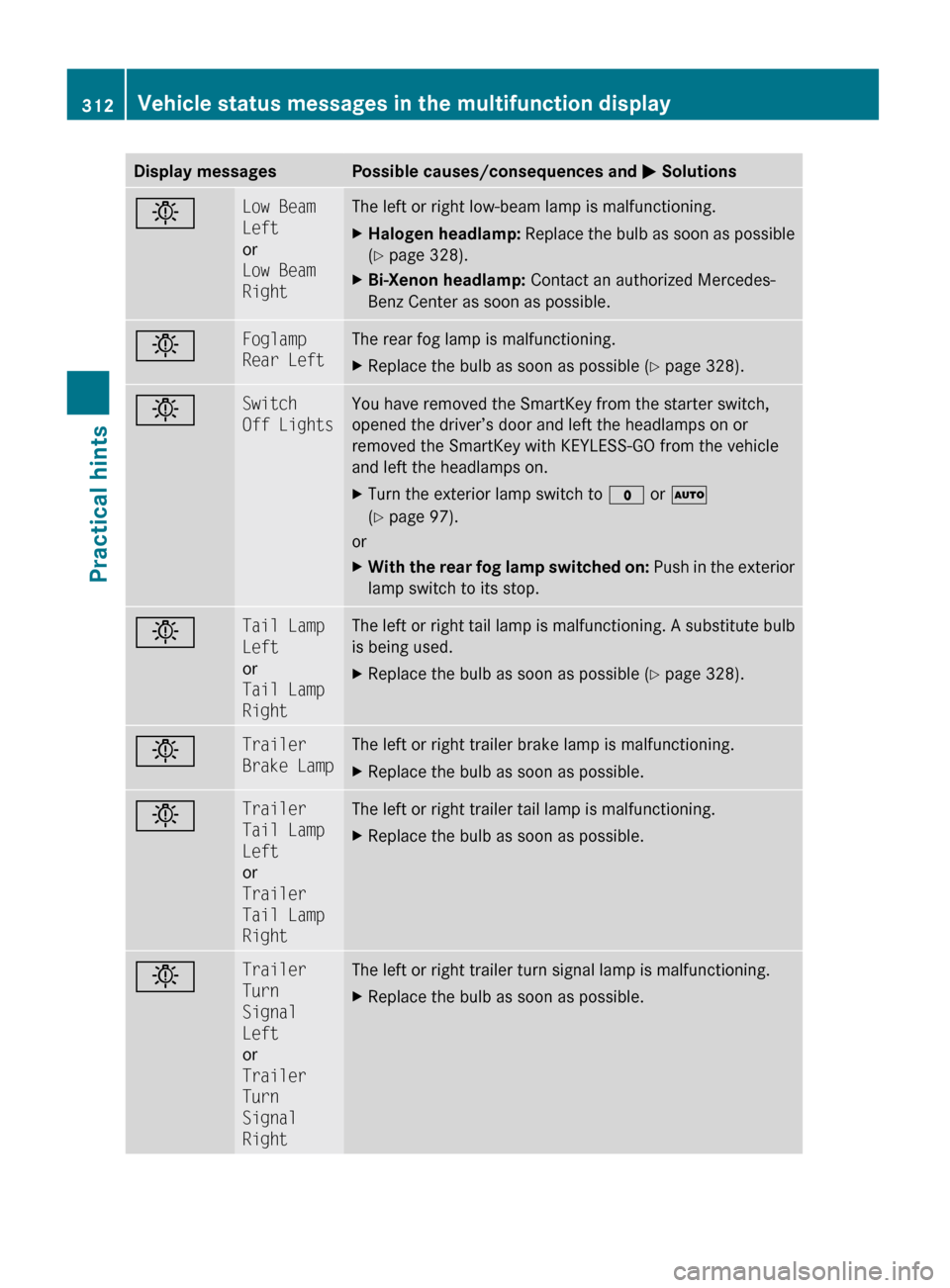
Display messagesPossible causes/consequences and M SolutionsbLow Beam
Left
or
Low Beam
RightThe left or right low-beam lamp is malfunctioning.XHalogen headlamp: Replace the bulb as soon as possible
( Y page 328).XBi-Xenon headlamp: Contact an authorized Mercedes-
Benz Center as soon as possible.bFoglamp
Rear LeftThe rear fog lamp is malfunctioning.XReplace the bulb as soon as possible ( Y page 328).bSwitch
Off LightsYou have removed the SmartKey from the starter switch,
opened the driver’s door and left the headlamps on or
removed the SmartKey with KEYLESS-GO from the vehicle
and left the headlamps on.XTurn the exterior lamp switch to $ or Ã
( Y page 97).
or
XWith the rear fog lamp switched on: Push in the exterior
lamp switch to its stop.bTail Lamp
Left
or
Tail Lamp
RightThe left or right tail lamp is malfunctioning. A substitute bulb
is being used.XReplace the bulb as soon as possible ( Y page 328).bTrailer
Brake LampThe left or right trailer brake lamp is malfunctioning.XReplace the bulb as soon as possible.bTrailer
Tail Lamp
Left
or
Trailer
Tail Lamp
RightThe left or right trailer tail lamp is malfunctioning.XReplace the bulb as soon as possible.bTrailer
Turn
Signal
Left
or
Trailer
Turn
Signal
RightThe left or right trailer turn signal lamp is malfunctioning.XReplace the bulb as soon as possible.312Vehicle status messages in the multifunction displayPractical hints
X164_AKB; 5; 31, en-USd2ureepe,Version: 2.11.8.12009-09-11T12:30:16+02:00 - Seite 312
Page 330 of 380
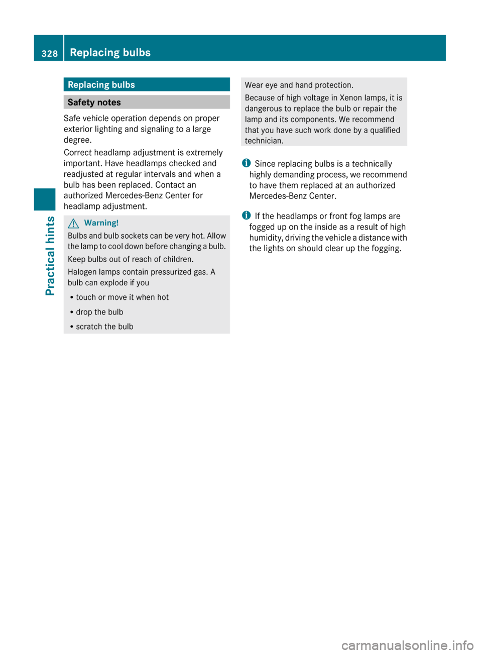
Replacing bulbs
Safety notes
Safe vehicle operation depends on proper
exterior lighting and signaling to a large
degree.
Correct headlamp adjustment is extremely
important. Have headlamps checked and
readjusted at regular intervals and when a
bulb has been replaced. Contact an
authorized Mercedes-Benz Center for
headlamp adjustment.
GWarning!
Bulbs and bulb sockets can be very hot. Allow
the lamp to cool down before changing a bulb.
Keep bulbs out of reach of children.
Halogen lamps contain pressurized gas. A
bulb can explode if you
R touch or move it when hot
R drop the bulb
R scratch the bulb
Wear eye and hand protection.
Because of high voltage in Xenon lamps, it is
dangerous to replace the bulb or repair the
lamp and its components. We recommend
that you have such work done by a qualified
technician.
i Since replacing bulbs is a technically
highly demanding process, we recommend
to have them replaced at an authorized
Mercedes-Benz Center.
i If the headlamps or front fog lamps are
fogged up on the inside as a result of high
humidity, driving the vehicle a distance with
the lights on should clear up the fogging.328Replacing bulbsPractical hints
X164_AKB; 5; 31, en-USd2ureepe,Version: 2.11.8.12009-09-11T12:30:16+02:00 - Seite 328
Page 332 of 380
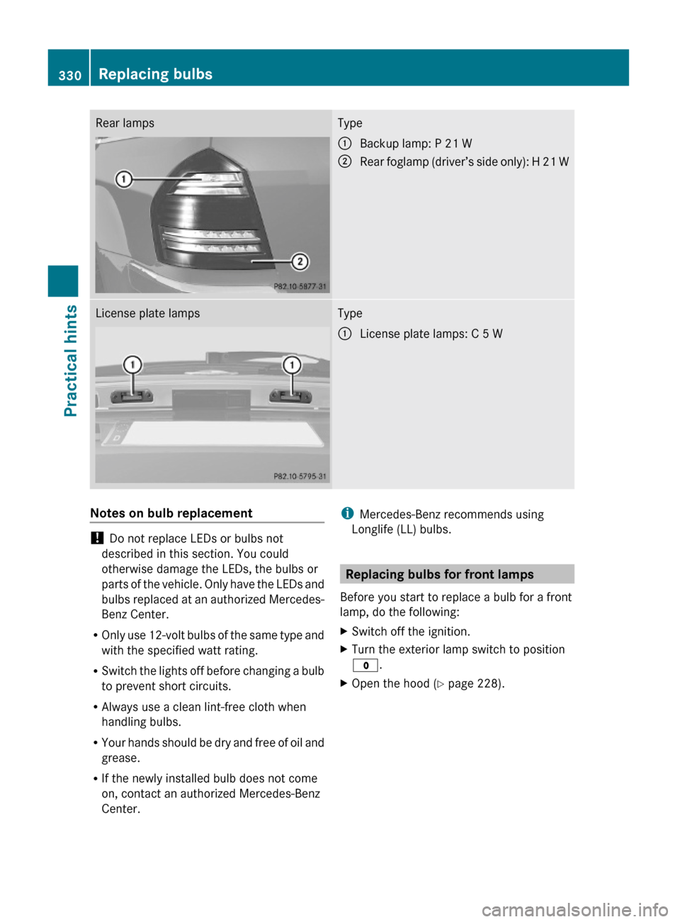
Rear lampsType:Backup lamp: P 21 W;Rear foglamp (driver’s side only): H 21 WLicense plate lampsType:License plate lamps: C 5 WNotes on bulb replacement
! Do not replace LEDs or bulbs not
described in this section. You could
otherwise damage the LEDs, the bulbs or
parts of the vehicle. Only have the LEDs and
bulbs replaced at an authorized Mercedes-
Benz Center.
ROnly use 12-volt bulbs of the same type and
with the specified watt rating.
RSwitch the lights off before changing a bulb
to prevent short circuits.
RAlways use a clean lint-free cloth when
handling bulbs.
RYour hands should be dry and free of oil and
grease.
RIf the newly installed bulb does not come
on, contact an authorized Mercedes-Benz
Center.
iMercedes-Benz recommends using
Longlife (LL) bulbs.
Replacing bulbs for front lamps
Before you start to replace a bulb for a front
lamp, do the following:
XSwitch off the ignition.XTurn the exterior lamp switch to position
$.
XOpen the hood (Y page 228).330Replacing bulbsPractical hints
X164_AKB; 5; 31, en-USd2ureepe,Version: 2.11.8.12009-09-11T12:30:16+02:00 - Seite 330
Page 340 of 380
iIf sealant has leaked out, let it dry. You
can then peel it off.
If clothing has come in contact with
TIREFIT, have it dry-cleaned with
perchloroethylene as soon as possible.
GWarning!
Observe safety instructions on air pump label.
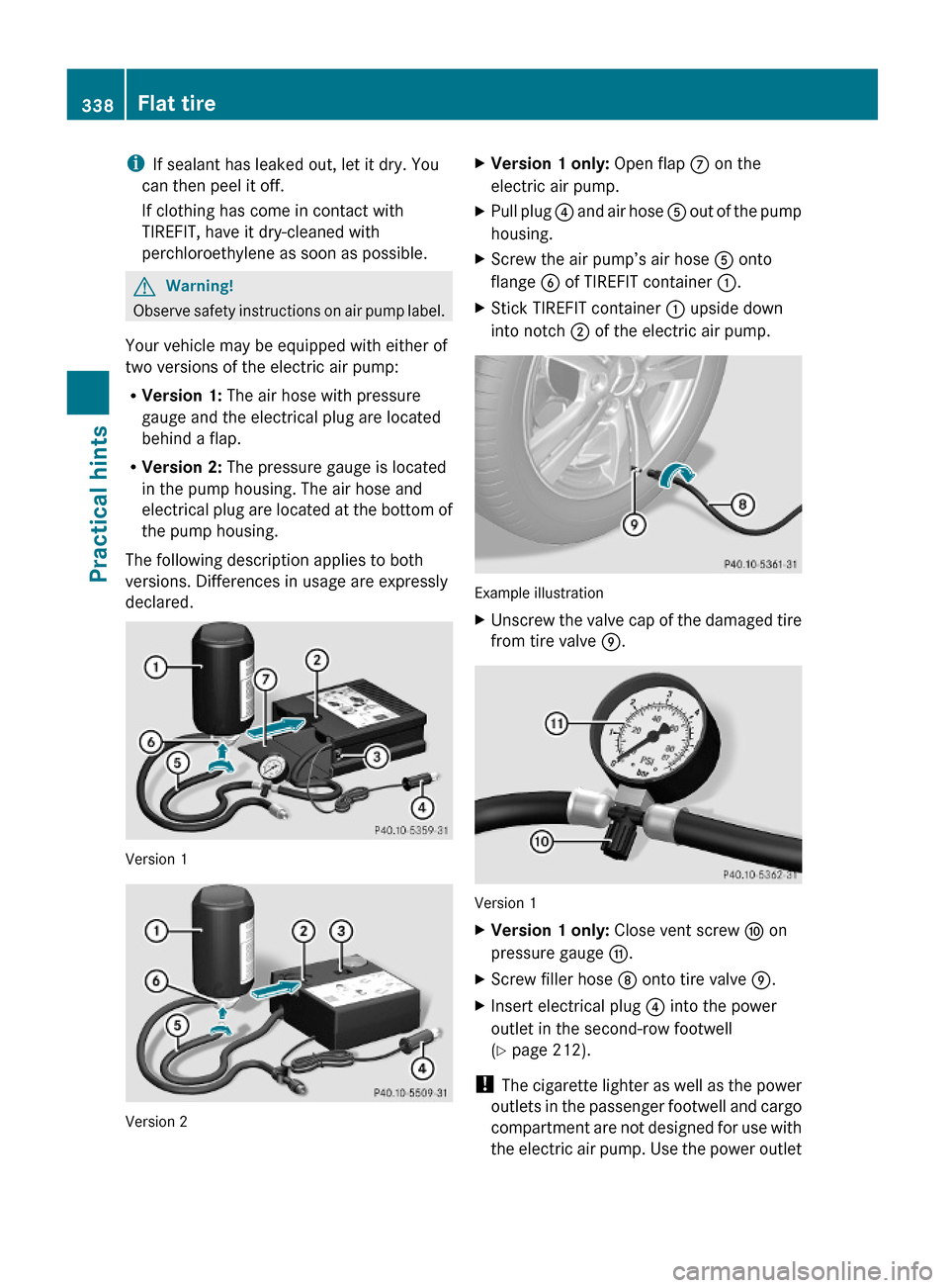
Your vehicle may be equipped with either of
two versions of the electric air pump:
RVersion 1: The air hose with pressure
gauge and the electrical plug are located
behind a flap.
RVersion 2: The pressure gauge is located
in the pump housing. The air hose and
electrical plug are located at the bottom of
the pump housing.
The following description applies to both
versions. Differences in usage are expressly
declared.
Version 1
Version 2
XVersion 1 only: Open flap C on the
electric air pump.
XPull plug ? and air hose A out of the pump
housing.
XScrew the air pump’s air hose A onto
flange B of TIREFIT container :.
XStick TIREFIT container : upside down
into notch ; of the electric air pump.
Example illustration
XUnscrew the valve cap of the damaged tire
from tire valve E.
Version 1
XVersion 1 only: Close vent screw F on
pressure gauge G.
XScrew filler hose D onto tire valve E.XInsert electrical plug ? into the power
outlet in the second-row footwell
(Y page 212).
! The cigarette lighter as well as the power
outlets in the passenger footwell and cargo
compartment are not designed for use with
the electric air pump. Use the power outlet
338Flat tirePractical hints
X164_AKB; 5; 31, en-USd2ureepe,Version: 2.11.8.12009-09-11T12:30:16+02:00 - Seite 338
Page 343 of 380
Lifting the vehicleGWarning!
When jacking up the vehicle, only use the jack
which has been specifically approved by
Mercedes-Benz for your vehicle.
The jack is designed exclusively for jacking up
the vehicle at the jack take-up brackets built
into both sides of the vehicle. Make sure the
jack arm is fully seated in the jack take-up
bracket. The jack must always be vertical
when in use, especially on inclines or
declines.
The jack is intended only for lifting the vehicle
briefly for wheel changes. It is not suited for
performing maintenance work under the
vehicle. To help avoid personal injury, use the
jack only to lift the vehicle during a wheel
change.
Never get beneath the vehicle while it is
supported by the jack. Keep hands and feet
away from the area under the lifted vehicle.
Always lower the vehicle onto sufficient
capacity jackstands before working under the
vehicle.
Always engage the parking brake firmly and
block the wheels with wheel chocks or other
sizeable objects before raising the vehicle
with the jack. Do not disengage the parking
brake while the vehicle is raised.
Make sure that the ground on which the
vehicle is standing and where you place the
jack is solid, level and not slippery. If
necessary, use a large underlay. On slippery
surfaces, such as tiled floors, you should use
a non-slip underlay, for example a rubber mat.
Do not use wooden blocks or similar objects
to support the jack. Otherwise the jack may
not be able to achieve its load-bearing
capacity if it is not at its full height.
Never start the engine when the vehicle is
raised.
Also observe the notes on the jack.
XPrevent the vehicle from rolling away by
blocking wheels with wheel chocks or other
sizeable objects.
When your vehicle is equipped with a wheel
chock, it is included with the vehicle tool kit
(Y page 284). For information on setting up
the collapsible wheel chock, see
(Y page 286).
GWarning!
Only jack up the vehicle on level ground or on
slight inclines/declines. Otherwise, the
vehicle could fall off the jack and injure you or
others.
Changing a wheel on a level surface
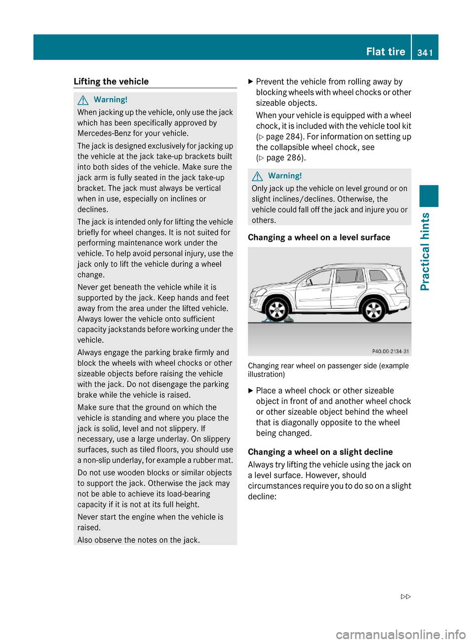
Changing rear wheel on passenger side (exampleillustration)
XPlace a wheel chock or other sizeable
object in front of and another wheel chock
or other sizeable object behind the wheel
that is diagonally opposite to the wheel
being changed.
Changing a wheel on a slight decline
Always try lifting the vehicle using the jack on
a level surface. However, should
circumstances require you to do so on a slight
decline:
Flat tire341Practical hintsX164_AKB; 5; 31, en-USd2ureepe,Version: 2.11.8.12009-09-11T12:30:16+02:00 - Seite 341Z
Page 344 of 380
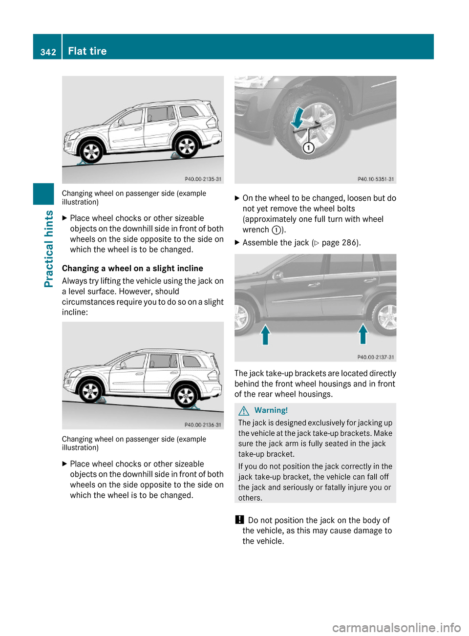
Changing wheel on passenger side (exampleillustration)
XPlace wheel chocks or other sizeable
objects on the downhill side in front of both
wheels on the side opposite to the side on
which the wheel is to be changed.
Changing a wheel on a slight incline
Always try lifting the vehicle using the jack on
a level surface. However, should
circumstances require you to do so on a slight
incline:
Changing wheel on passenger side (exampleillustration)
XPlace wheel chocks or other sizeable
objects on the downhill side in front of both
wheels on the side opposite to the side on
which the wheel is to be changed.
XOn the wheel to be changed, loosen but do
not yet remove the wheel bolts
(approximately one full turn with wheel
wrench :).
XAssemble the jack (Y page 286).
The jack take-up brackets are located directly
behind the front wheel housings and in front
of the rear wheel housings.
GWarning!
The jack is designed exclusively for jacking up
the vehicle at the jack take-up brackets. Make
sure the jack arm is fully seated in the jack
take-up bracket.
If you do not position the jack correctly in the
jack take-up bracket, the vehicle can fall off
the jack and seriously or fatally injure you or
others.
! Do not position the jack on the body of
the vehicle, as this may cause damage to
the vehicle.
342Flat tirePractical hints
X164_AKB; 5; 31, en-USd2ureepe,Version: 2.11.8.12009-09-11T12:30:16+02:00 - Seite 342
Page 346 of 380
Do not tighten the wheel bolts when the
vehicle is raised. Otherwise the vehicle could
fall off the jack.
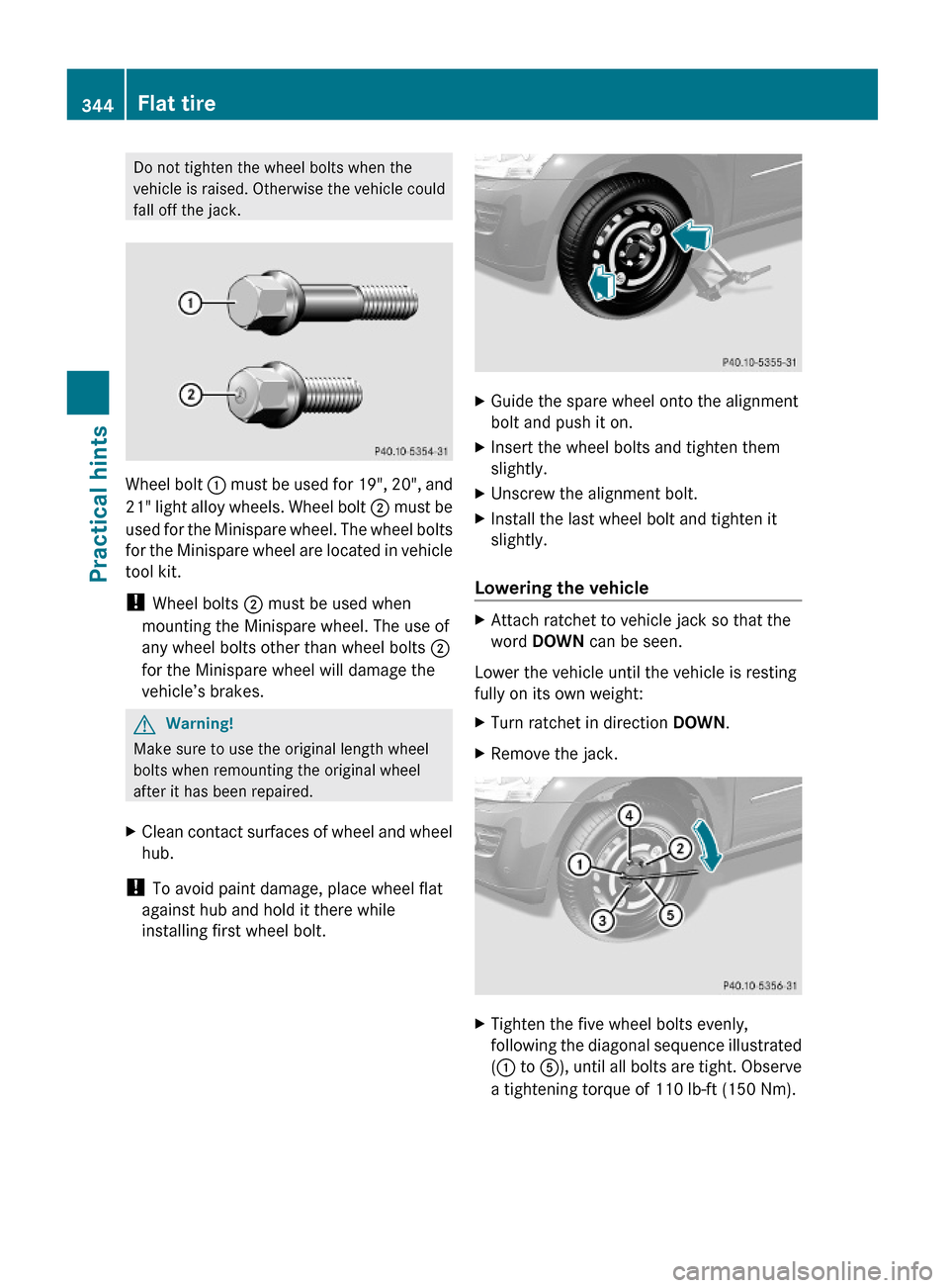
Wheel bolt : must be used for 19", 20", and
21" light alloy wheels. Wheel bolt ; must be
used for the Minispare wheel. The wheel bolts
for the Minispare wheel are located in vehicle
tool kit.
! Wheel bolts ; must be used when
mounting the Minispare wheel. The use of
any wheel bolts other than wheel bolts ;
for the Minispare wheel will damage the
vehicle’s brakes.
GWarning!
Make sure to use the original length wheel
bolts when remounting the original wheel
after it has been repaired.
XClean contact surfaces of wheel and wheel
hub.
! To avoid paint damage, place wheel flat
against hub and hold it there while
installing first wheel bolt.
XGuide the spare wheel onto the alignment
bolt and push it on.
XInsert the wheel bolts and tighten them
slightly.
XUnscrew the alignment bolt.XInstall the last wheel bolt and tighten it
slightly.
Lowering the vehicle
XAttach ratchet to vehicle jack so that the
word DOWN can be seen.
Lower the vehicle until the vehicle is resting
fully on its own weight:
XTurn ratchet in direction DOWN.XRemove the jack.XTighten the five wheel bolts evenly,
following the diagonal sequence illustrated
(: to A), until all bolts are tight. Observe
a tightening torque of 110 lb-ft (150 Nm).
344Flat tirePractical hints
X164_AKB; 5; 31, en-USd2ureepe,Version: 2.11.8.12009-09-11T12:30:16+02:00 - Seite 344
Page 369 of 380
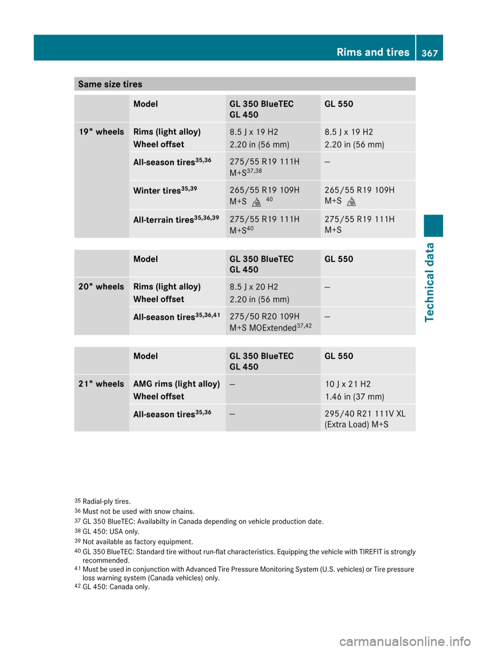
Same size tiresModelGL 350 BlueTEC
GL 450GL 55019" wheelsRims (light alloy)
Wheel offset8.5 J x 19 H2
2.20 in (56 mm)8.5 J x 19 H2
2.20 in (56 mm)All-season tires 35,36275/55 R19 111H
M+S 37,38—Winter tires 35,39265/55 R19 109H
M+S i 40265/55 R19 109H
M+S iAll-terrain tires 35,36,39275/55 R19 111H
M+S 40275/55 R19 111H
M+SModelGL 350 BlueTEC
GL 450GL 55020" wheelsRims (light alloy)
Wheel offset8.5 J x 20 H2
2.20 in (56 mm)—All-season tires 35,36,41275/50 R20 109H
M+S MOExtended 37,42—ModelGL 350 BlueTEC
GL 450GL 55021" wheelsAMG rims (light alloy)
Wheel offset—10 J x 21 H2
1.46 in (37 mm)All-season tires 35,36—295/40 R21 111V XL
(Extra Load) M+S35 Radial-ply tires.
36 Must not be used with snow chains.
37 GL 350 BlueTEC: Availabilty in Canada depending on vehicle production date.
38 GL 450: USA only.
39 Not available as factory equipment.
40 GL 350 BlueTEC: Standard tire without run-flat characteristics. Equipping the vehicle with TIREFIT is strongly
recommended.
41 Must be used in conjunction with Advanced Tire Pressure Monitoring System (U.S. vehicles) or Tire pressure
loss warning system (Canada vehicles) only.
42 GL 450: Canada only.Rims and tires367Technical dataX164_AKB; 5; 31, en-USd2ureepe,Version: 2.11.8.12009-09-11T12:30:16+02:00 - Seite 367Z