2010 MERCEDES-BENZ GL450 torque
[x] Cancel search: torquePage 19 of 380
Capacities fuels, coolants,
lubricants etc. ................................ 368
Coolant .......................................... 373
Engine oil additives ........................371
Engine oils ..................................... 370
Fuel requirements .......................... 371
Gasoline additives .......................... 372
Identification labels .......................360
Premium unleaded gasoline ...........371
Rims and tires ................................ 365
Spare wheel ................................... 368
Vehicle specification
GL 350 BlueTEC ............................. 362
Vehicle specification GL 450 .........362
Vehicle specification GL 550 .........363
Washer and headlamp cleaning
system ................................... 370, 375
Technical data (dimensions)
see Vehicle specification
Technical data (electrical system)
see Vehicle specification
Technical data (engine)
see Vehicle specification
Technical data (weights)
see Vehicle specification
Tele Aid ............................................... 214
Emergency calls ............................. 215
Information button .........................217
Initiating an emergency call
manually ........................................ 216
Messages in the multifunction
display ........................................... 301
Remote door unlock ......................219
Roadside Assistance button ..........216
Search & Send ............................... 218
SOS button .................................... 216
Stolen Vehicle Recovery Services ..219
System self-test ............................. 215
Telephone ............................................. 30
Answering/ending a call ................143
Hands-free microphone ...................34
Menu ............................................. 142
Operation ....................................... 142
Phone book .................................... 143
Redialing ........................................ 144
Temperature
Interior temperature ..............178, 187
Outside .................................. 129, 135Tether anchorage points
see Children in the vehicle
Tie-down rings ................................... 200
Tightening torque
Wheels ........................................... 344
Time setting ....................................... 135
TIN (Tire Identification Number) ...... 256
Tire and Loading Information
placard ............................................... 242
Tire and loading terminology ........... 254
TIREFIT ............................................... 337
Tire Identification Number see TIN
Tire inflation pressure
Checking ........................................ 237
Important notes on ........................235
Label on the inside of fuel filler
flap ................................................ 236
Placard on driver’s door B-pillar .....242
Tire labeling ....................................... 250
Tire load rating .................................. 255
Tire ply composition and material
used .................................................... 256
Tire pressure loss warning system . 237
Tire repair kit see TIREFIT
Tires ........................................... 233, 365
Advanced Tire Pressure
Monitoring System (Advanced
TPMS) ............................................ 239
Air pressure ................................... 234
Care and maintenance ...................247
Cleaning ......................................... 248
Direction of rotation, spinning .......246
Important notes on tire inflation
pressure ........................................ 235
Inflation pressure ..................236, 237
Information placard .......................242
Inspection ...................................... 247
Labeling ......................................... 250
Load index ............................. 251, 255
Load rating .................................... 255
Messages in the multifunction
display ................................... 297, 313
MOExtended .................................. 365
Ply composition and material
used ............................................... 256Index17X164_AKB; 5; 31, en-USd2ureepe,Version: 2.11.8.12009-09-11T12:30:16+02:00 - Seite 17
Page 21 of 380
Modifications and alterations,
Operating safety .............................. 23
Towing ........................................... 352
Unlocking/locking manually ..........323
Vehicle configuration menu ............. 140
Vehicle dimensions see Vehicle specification
Vehicle Identification Number
(VIN) ................................................... 360
Vehicle jack see Jack
Vehicle level control
see Air suspension program
Vehicle lighting .................................... 97
Vehicle loading
Cargo tie-down rings ...................... 200
Cargo volume, expanding ..............201
Carriers .......................................... 196
Instructions .................................... 194
Load limit ....................................... 243
Terminology ................................... 254
Vehicle maximum load on the tire ... 257
Vehicle specification
GL 350 BlueTEC ............................. 362
GL 450 ........................................... 362
GL 550 ........................................... 363
Vehicle status message memory .... 131
Vehicle tool kit .................................. 284
Vehicle washing see Vehicle care
Vehicle weights
see Vehicle specification
W
Warning lamps see Lamps, Indicator and warning
Warning sounds
Distance warning function .............155
Distronic ........................................ 149
Driver’s or passenger’s seat belt .....51
Parking brake ................................ 300
Parktronic system ..........................169
Seat belt telltale ............................ 317
Warranty coverage ............................ 360
Washer and headlamp cleaning
system ................................................ 375
Washer fluid
Messages in the multifunction
display ........................................... 305
Mixing ratio .................................... 375
Refilling .......................................... 232
Washing the vehicle .......................... 275
Wear pattern (tires) .......................... 249
Weights (vehicle) see Vehicle specification
Wheel
Changing ....................................... 336
Removing ....................................... 343
Spare ............................................. 336
Tightening torque ........................... 344
Wheels, sizes ..................................... 365
Wheels, Tires and .............................. 233
Window curtain air bags ..................... 42
Windows see Power windows
Windows, cleaning ............................ 278
Windshield
Cleaning wiper blades .................... 278
Infrared reflecting ..........................223
Washer fluid ................................... 375
Wipers ........................................... 103
Windshield wipers
Replacing wiper blades ..................334
Winter cover .............................. 230, 257
Winter driving
Instructions .................................... 258
Radiator cover ............................... 257
Snow chains .................................. 258
Tires ............................................... 257
Winter tires ................................ 257, 365
Wood trims, cleaning ........................ 280Index19X164_AKB; 5; 31, en-USd2ureepe,Version: 2.11.8.12009-09-11T12:30:16+02:00 - Seite 19
Page 124 of 380
and rear axle differential to improve vehicle
traction.
The center differential compensates for
differences in wheel rotation between the
front and rear axle.
The rear axle differential compensates
differences between the rear wheels.
i At the front axles, the 4-ETS system
compensates for any traction problems.
For more information on off-road driving, see
“Off-road driving” ( Y page 262).
A few words about differentials and
differential locks
When a vehicle negotiates a turn, wheels on
the outside of the curve must travel farther
and rotate faster than the inside wheels. The
differential, the operation of a set of gears
that allows the powered wheels in a vehicle
to turn at different speeds, makes this
essential function possible.
The drawback is that the differential also
sends most of the engine’s power to the
wheel with the least load or strain on it. For
example, if one of a vehicle’s powered wheels
sits on a patch of snow and spins because
there is no traction, all of the engine’s power
will go to that wheel because the power will
take the path of least resistance. Meanwhile,
the opposite wheel, sitting on dry pavement
where it could get enough grip to start the
vehicle moving, sits idle because it receives
no power.
The 4-ETS addresses this problem and
provides for good control and steering ability
by automatically slowing the slipping wheel
and thus increasing the power to the other
non-slipping drive wheels to get the vehicle
moving. The ESP ®
and the 4-ETS in this
vehicle feature such intelligent limited-slip
differential technology, ideally suited for on-
road and light off-road driving. Transfer case
position LOW (Y page 120) also enhances off-
road driving capabilities.
More extreme off-road conditions may call for
another solution, engaging a differential lock
or preventing the differential from operating
altogether. This vehicle comes with two
differential locks: transfer case (center) and
rear. Each can be engaged simply by
operating the rotary switch located on the
center console ( Y page 123). When the
transfer case (center) differential is locked,
the combined (or average) speed of the front
wheels is identical to the combined rear
wheel speed. When the rear differential is
locked, both rear wheels turn at the same
speed, independent of the individual torque.
Please be aware that engaging the differential
locks will significantly reduce the steering
ability of the vehicle.
For your safety and the safety of others and
to prevent damage to the vehicle, the
differential locks must not be engaged when
driving on paved roads. It is important to
understand that during on-road/paved
driving, differentials are absolutely necessary
for providing the essential control and
steering ability of the vehicle. The differential
locks, therefore, must not be engaged when
driving on paved roads and should only be
used to the extent necessary to negotiate off-
road conditions which cannot be handled by
the systems (the 4-ETS, the ESP ®
, and the
transfer case in LOW RANGE mode) this
vehicle comes equipped with.
Switching differential locks
! If the differential locks are engaged,
accelerate gently when setting the vehicle
in motion.
Only operate the vehicle on a single axle
dynamometer if the axle not being driven is
jacked up or the associated propeller shaft
is disconnected.
Otherwise the transmission could be
damaged.
122Differential locksControls in detail
X164_AKB; 5; 31, en-USd2ureepe,Version: 2.11.8.12009-09-11T12:30:16+02:00 - Seite 122
Page 200 of 380
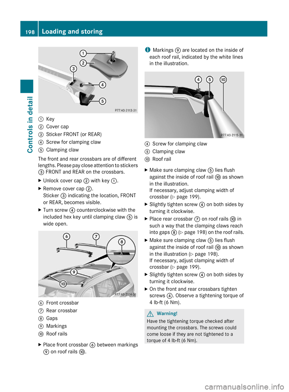
:Key;Cover cap=Sticker FRONT (or REAR)?Screw for clamping clawAClamping claw
The front and rear crossbars are of different
lengths. Please pay close attention to stickers
= FRONT and REAR on the crossbars.
XUnlock cover cap ; with key :.XRemove cover cap ;.
Sticker = indicating the location, FRONT
or REAR, becomes visible.
XTurn screw ? counterclockwise with the
included hex key until clamping claw A is
wide open.
BFront crossbarCRear crossbarDGapsEMarkingsFRoof railsXPlace front crossbar B between markings
E on roof rails F.
iMarkings E are located on the inside of
each roof rail, indicated by the white lines
in the illustration.
?Screw for clamping clawAClamping clawFRoof railXMake sure clamping claw A lies flush
against the inside of roof rail F as shown
in the illustration.
If necessary, adjust clamping width of
crossbar (Y page 199).
XSlightly tighten screw ? on both sides by
turning it clockwise.
XPlace rear crossbar C on roof rails F in
such a way that the clamping claws reach
into gaps D (Y page 198) on the roof rails.
XMake sure clamping claw A lies flush
against the inside of roof rail F as shown
in the illustration (Y page 198).
If necessary, adjust clamping width of
crossbar (Y page 199).
XSlightly tighten screw ? on both sides by
turning it clockwise.
XOn the front and rear crossbars tighten
screws ?. Observe a tightening torque of
4 lb-ft (6 Nm).
GWarning!
Have the tightening torque checked after
mounting the crossbars. The screws could
come loose if they are not tightened to a
torque of 4 lb-ft (6 Nm).
198Loading and storingControls in detail
X164_AKB; 5; 31, en-USd2ureepe,Version: 2.11.8.12009-09-11T12:30:16+02:00 - Seite 198
Page 201 of 380
XAttach cover caps (Y page 198) and lock
them.
XStore key and hex key back into the storage
well (Y page 284).
Adjusting the clamping widths of the
crossbars
GWarning!
Only install the crossbars at the exact
locations designated on the roof rails. The
designated locations for the front crossbars
are between the markings engraved on the
inside of the roof rails. The designated
locations for the rear crossbars are between
the gaps on the roof rails.
Otherwise, the crossbars, mounted
accessories and the objects attached to them
could come loose from the vehicle causing an
accident, thereby injuring you and other
persons and/or causing damage to property,
including damage to your vehicle.
The clamping widths of the crossbars are
factory set for your vehicle. These clamping
widths are solely intended for the designated
positions.
Only install the crossbars at the designated
locations and pay attention to the stickers
= FRONT and REAR (Y page 198).
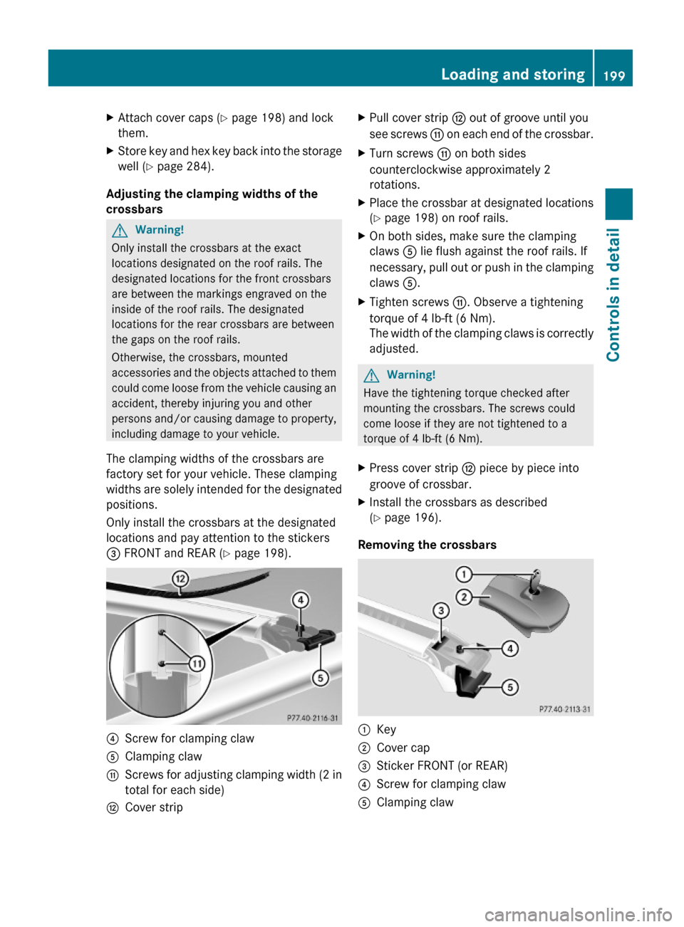
?Screw for clamping clawAClamping clawGScrews for adjusting clamping width (2 in
total for each side)
HCover stripXPull cover strip H out of groove until you
see screws G on each end of the crossbar.
XTurn screws G on both sides
counterclockwise approximately 2
rotations.
XPlace the crossbar at designated locations
(Y page 198) on roof rails.
XOn both sides, make sure the clamping
claws A lie flush against the roof rails. If
necessary, pull out or push in the clamping
claws A.
XTighten screws G. Observe a tightening
torque of 4 lb-ft (6 Nm).
The width of the clamping claws is correctly
adjusted.
GWarning!
Have the tightening torque checked after
mounting the crossbars. The screws could
come loose if they are not tightened to a
torque of 4 lb-ft (6 Nm).
XPress cover strip H piece by piece into
groove of crossbar.
XInstall the crossbars as described
(Y page 196).
Removing the crossbars
:Key;Cover cap=Sticker FRONT (or REAR)?Screw for clamping clawAClamping clawLoading and storing199Controls in detailX164_AKB; 5; 31, en-USd2ureepe,Version: 2.11.8.12009-09-11T12:30:16+02:00 - Seite 199Z
Page 251 of 380

tests, and does not include acceleration,
cornering, hydroplaning, or peak traction
characteristics.
The traction grades, from highest to lowest,
are AA, A, B, and C. Those grades represent
the tire’s ability to stop on wet pavement as
measured under controlled conditions on
specified government test surfaces of asphalt
and concrete. A tire marked C may have poor
traction performance.GWarning!
If ice has formed on the road, tire traction will
be substantially reduced. Under such weather
conditions, drive, steer and brake with
extreme caution.
The safe speed on a wet, snow covered or icy
road is always lower than on a dry road.
You should pay particular attention to the
condition of the road whenever the outside
temperature is close to the freezing point.
Mercedes-Benz recommends winter tires
( Y page 257) with a minimum tread depth of
approximately 1
/ 6 in (4 mm) on all four wheels
for the winter season to ensure normal
balanced handling characteristics. On
packed snow, they can reduce your stopping
distance compared to summer tires.
Stopping distance, however, is still
considerably greater than when the road is
not covered with snow or ice. Exercise
appropriate caution.
! Avoid spinning of a drive wheel. This may
cause serious damage to the drivetrain
which is not covered by the Mercedes-Benz
Limited Warranty.
Temperature
GWarning!
The temperature grade for this tire is
established for a tire that is properly inflated
and not overloaded. Excessive speed,
underinflation, or excessive loading, either
separately or in combination, can cause
excessive heat build-up and possible tire
failure.
The temperature grades are A (the highest),
B, and C, representing the tire’s resistance to
the generation of heat and its ability to
dissipate heat when tested under controlled
conditions on a specified indoor laboratory
test wheel. Sustained high temperature can
cause the material of the tire to degenerate
and reduce tire life, and excessive
temperature can lead to sudden tire failure.
The grade C corresponds to a level of
performance which all passenger car tires
must meet under the Federal Motor Vehicle
Safety Standard No. 109. Grades B and A
represent higher levels of performance on the
laboratory test wheel than the minimum
required by law.
Rotating tires
GWarning!
Rotate front and rear wheels only if the tires
are of the same dimension.
If your vehicle is equipped with mixed-size
tires (different tire dimensions front vs. rear),
tire rotation is not possible.
GWarning!
Have the tightening torque checked after
changing a wheel. The wheels could come
loose if they are not tightened to a torque of
110 lb-ft (150 Nm).
Only use genuine Mercedes-Benz wheel bolts
specified for your vehicle’s rims.
Tire rotation can be performed on vehicles
with tires of the same dimension all around.
If your vehicle is equipped with tires of the
same dimension all around, tires can be
rotated, observing a front-to-rear rotation
pattern that will maintain the intended
rotation (spinning) direction of the tire
( Y page 246).
In some cases, such as when your vehicle is
equipped with mixed-size tires (different tire
Tires and wheels249OperationX164_AKB; 5; 31, en-USd2ureepe,Version: 2.11.8.12009-09-11T12:30:16+02:00 - Seite 249Z
Page 267 of 380
100% grade which is equivalent to a slope
angle of 45°. Keep in mind that the
climbing ability of the vehicle depends on
terrain conditions.
R Shift automatic transmission into gear
range 1 (Y page 118).
R Drive slowly.
R Avoid excessive engine speeds – drive with
moderate engine speeds (max. 3 000 rpm).
R Utilize the engine’s braking power when
descending a slope, observe the engine
speed (do not overrev the engine). Apply
the service brake as needed.
i For maximum engine speed, see
“Tachometer” (Y page 125) and see vehicle
specification for your vehicle
( Y page 362).
R Check the brakes after a lengthy
downgrade drive.GWarning!
Never turn the vehicle around on steep
inclines. The vehicle might roll over. If the
vehicle cannot complete the attempted climb,
back it down in reverse gear.
i The hill-start assist system supports you
when driving uphill.
For more information, see “Hill-start assist
system” ( Y page 155).
Traction in steep terrain
The maximum vehicle climbing ability is a
100% grade which is equivalent to a slope
angle of 45°. Keep in mind that the climbing
ability of the vehicle depends on terrain
conditions.
Be easy on the accelerator and watch for
continuous wheel traction when driving in
steep terrain.
i The 4-ETS helps greatly when starting out
on a steep incline when the front wheels
have then the tendency to slip due to the
weight shifting towards the rear axle.
The 4-ETS recognizes the situation and
limits the torque for the front wheels by
braking them.
Simultaneously the torque for the rear
wheels is increased.
i Vehicles with enhanced off-road package
are equipped with automatic locks for the
center and rear axle differential to improve
vehicle traction.
Driving across a hilltop
Decelerate just ahead of a hilltop (do not shift
automatic transmission into neutral position
N ), to prevent the vehicle from speeding up
too much after climbing a hill.
Use the momentum of the vehicle to drive
across the hilltop.
After climbing a hill, driving in this manner
prevents the vehicle from:
R losing ground contact when cresting hills
R losing its forward momentum
R speeding up too much after climbing the hill
Driving downhill
R Drive slowly.
R Do not drive at an angle to the incline. Steer
into the line of gravity and drive with the
front wheels pointing straight downhill.
Otherwise, the vehicle may slide sideways
off the path and roll over.
R Shift automatic transmission into gear
range 1 (Y page 118).
R On steep inclines, use the Downhill Speed
Regulation ( Y page 155).
R Utilize the engine’s braking power to
reduce vehicle speed.
If this is insufficient, apply the brakes
gently. Make sure the vehicle is moving in
the line of gravity.
R Check the brakes after a lengthy
downgrade drive.
Driving instructions265OperationX164_AKB; 5; 31, en-USd2ureepe,Version: 2.11.8.12009-09-11T12:30:16+02:00 - Seite 265Z
Page 346 of 380
Do not tighten the wheel bolts when the
vehicle is raised. Otherwise the vehicle could
fall off the jack.
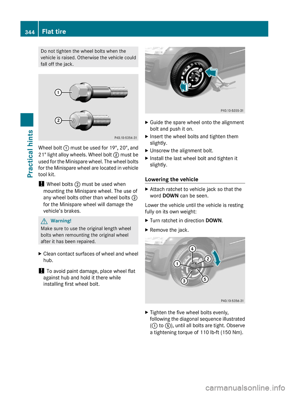
Wheel bolt : must be used for 19", 20", and
21" light alloy wheels. Wheel bolt ; must be
used for the Minispare wheel. The wheel bolts
for the Minispare wheel are located in vehicle
tool kit.
! Wheel bolts ; must be used when
mounting the Minispare wheel. The use of
any wheel bolts other than wheel bolts ;
for the Minispare wheel will damage the
vehicle’s brakes.
GWarning!
Make sure to use the original length wheel
bolts when remounting the original wheel
after it has been repaired.
XClean contact surfaces of wheel and wheel
hub.
! To avoid paint damage, place wheel flat
against hub and hold it there while
installing first wheel bolt.
XGuide the spare wheel onto the alignment
bolt and push it on.
XInsert the wheel bolts and tighten them
slightly.
XUnscrew the alignment bolt.XInstall the last wheel bolt and tighten it
slightly.
Lowering the vehicle
XAttach ratchet to vehicle jack so that the
word DOWN can be seen.
Lower the vehicle until the vehicle is resting
fully on its own weight:
XTurn ratchet in direction DOWN.XRemove the jack.XTighten the five wheel bolts evenly,
following the diagonal sequence illustrated
(: to A), until all bolts are tight. Observe
a tightening torque of 110 lb-ft (150 Nm).
344Flat tirePractical hints
X164_AKB; 5; 31, en-USd2ureepe,Version: 2.11.8.12009-09-11T12:30:16+02:00 - Seite 344