2010 MERCEDES-BENZ GL tailgate
[x] Cancel search: tailgatePage 289 of 380
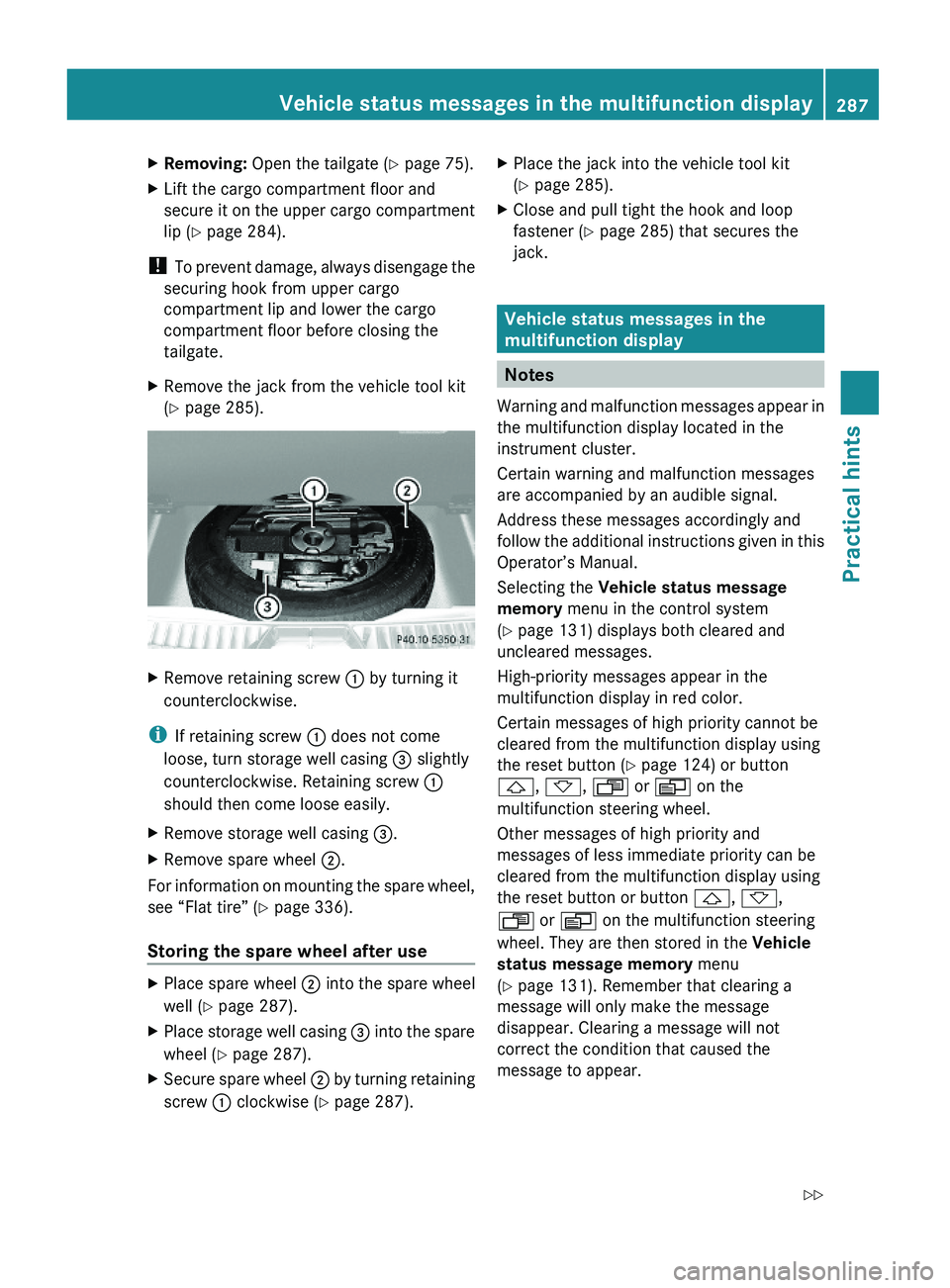
XRemoving: Open the tailgate (Y page 75).XLift the cargo compartment floor and
secure it on the upper cargo compartment
lip (Y page 284).
! To prevent damage, always disengage the
securing hook from upper cargo
compartment lip and lower the cargo
compartment floor before closing the
tailgate.
XRemove the jack from the vehicle tool kit
(Y page 285).
XRemove retaining screw : by turning it
counterclockwise.
iIf retaining screw : does not come
loose, turn storage well casing = slightly
counterclockwise. Retaining screw :
should then come loose easily.
XRemove storage well casing =.XRemove spare wheel ;.
For information on mounting the spare wheel,
see “Flat tire” (Y page 336).
Storing the spare wheel after use
XPlace spare wheel ; into the spare wheel
well (Y page 287).
XPlace storage well casing = into the spare
wheel (Y page 287).
XSecure spare wheel ; by turning retaining
screw : clockwise (Y page 287).
XPlace the jack into the vehicle tool kit
(Y page 285).
XClose and pull tight the hook and loop
fastener (Y page 285) that secures the
jack.
Vehicle status messages in the
multifunction display
Notes
Warning and malfunction messages appear in
the multifunction display located in the
instrument cluster.
Certain warning and malfunction messages
are accompanied by an audible signal.
Address these messages accordingly and
follow the additional instructions given in this
Operator’s Manual.
Selecting the Vehicle status message
memory menu in the control system
(Y page 131) displays both cleared and
uncleared messages.
High-priority messages appear in the
multifunction display in red color.
Certain messages of high priority cannot be
cleared from the multifunction display using
the reset button (Y page 124) or button
&, *, U or V on the
multifunction steering wheel.
Other messages of high priority and
messages of less immediate priority can be
cleared from the multifunction display using
the reset button or button &, *,
U or V on the multifunction steering
wheel. They are then stored in the Vehicle
status message memory menu
(Y page 131). Remember that clearing a
message will only make the message
disappear. Clearing a message will not
correct the condition that caused the
message to appear.
Vehicle status messages in the multifunction display287Practical hintsX164_AKB; 5; 31, en-USd2ureepe,Version: 2.11.8.12009-09-11T12:30:16+02:00 - Seite 287Z
Page 306 of 380
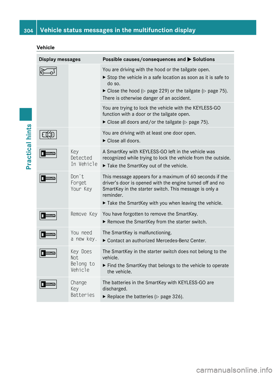
VehicleDisplay messagesPossible causes/consequences and M SolutionsEYou are driving with the hood or the tailgate open.XStop the vehicle in a safe location as soon as it is safe to
do so.XClose the hood ( Y page 229) or the tailgate ( Y page 75).
There is otherwise danger of an accident.
You are trying to lock the vehicle with the KEYLESS-GO
function with a door or the tailgate open.XClose all doors and/or the tailgate ( Y page 75).;You are driving with at least one door open.XClose all doors.+Key
Detected
In VehicleA SmartKey with KEYLESS-GO left in the vehicle was
recognized while trying to lock the vehicle from the outside.XTake the SmartKey out of the vehicle.+Don’t
Forget
Your KeyThis message appears for a maximum of 60 seconds if the
driver’s door is opened with the engine turned off and no
SmartKey in the starter switch. This message is only a
reminder.XTake the SmartKey with you when leaving the vehicle.+Remove KeyYou have forgotten to remove the SmartKey.XRemove the SmartKey from the starter switch.+You need
a new key.The SmartKey is malfunctioning.XContact an authorized Mercedes-Benz Center.+Key Does
Not
Belong to
VehicleThe SmartKey in the starter switch does not belong to the
vehicle.XFind the SmartKey that belongs to the vehicle to operate
the vehicle.+Change
Key
BatteriesThe batteries in the SmartKey with KEYLESS-GO are
discharged.XReplace the batteries ( Y page 326).304Vehicle status messages in the multifunction displayPractical hints
X164_AKB; 5; 31, en-USd2ureepe,Version: 2.11.8.12009-09-11T12:30:16+02:00 - Seite 304
Page 326 of 380
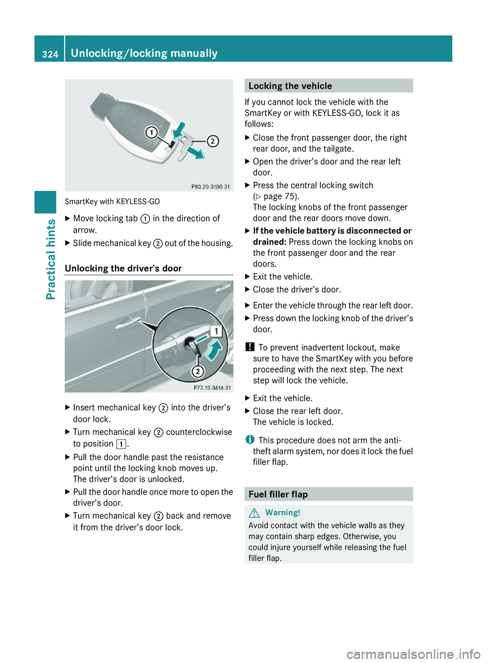
SmartKey with KEYLESS-GO
XMove locking tab : in the direction of
arrow.
XSlide mechanical key ; out of the housing.
Unlocking the driver’s door
XInsert mechanical key ; into the driver’s
door lock.
XTurn mechanical key ; counterclockwise
to position 1.
XPull the door handle past the resistance
point until the locking knob moves up.
The driver’s door is unlocked.
XPull the door handle once more to open the
driver’s door.
XTurn mechanical key ; back and remove
it from the driver’s door lock.Locking the vehicle
If you cannot lock the vehicle with the
SmartKey or with KEYLESS-GO, lock it as
follows:
XClose the front passenger door, the right
rear door, and the tailgate.
XOpen the driver’s door and the rear left
door.
XPress the central locking switch
(Y page 75).
The locking knobs of the front passenger
door and the rear doors move down.
XIf the vehicle battery is disconnected or
drained: Press down the locking knobs on
the front passenger door and the rear
doors.
XExit the vehicle.XClose the driver’s door.XEnter the vehicle through the rear left door.XPress down the locking knob of the driver’s
door.
! To prevent inadvertent lockout, make
sure to have the SmartKey with you before
proceeding with the next step. The next
step will lock the vehicle.
XExit the vehicle.XClose the rear left door.
The vehicle is locked.
iThis procedure does not arm the anti-
theft alarm system, nor does it lock the fuel
filler flap.
Fuel filler flap
GWarning!
Avoid contact with the vehicle walls as they
may contain sharp edges. Otherwise, you
could injure yourself while releasing the fuel
filler flap.
324Unlocking/locking manuallyPractical hints
X164_AKB; 5; 31, en-USd2ureepe,Version: 2.11.8.12009-09-11T12:30:16+02:00 - Seite 324
Page 327 of 380
In case the central locking system does not
release the fuel filler flap, you can open it
manually.
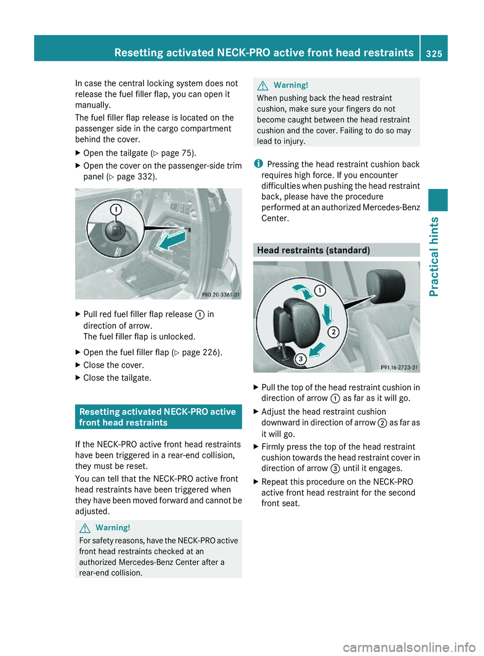
The fuel filler flap release is located on the
passenger side in the cargo compartment
behind the cover.
XOpen the tailgate (Y page 75).XOpen the cover on the passenger-side trim
panel (Y page 332).
XPull red fuel filler flap release : in
direction of arrow.
The fuel filler flap is unlocked.
XOpen the fuel filler flap (Y page 226).XClose the cover.XClose the tailgate.
Resetting activated NECK-PRO active
front head restraints
If the NECK-PRO active front head restraints
have been triggered in a rear-end collision,
they must be reset.
You can tell that the NECK-PRO active front
head restraints have been triggered when
they have been moved forward and cannot be
adjusted.
GWarning!
For safety reasons, have the NECK-PRO active
front head restraints checked at an
authorized Mercedes-Benz Center after a
rear-end collision.
GWarning!
When pushing back the head restraint
cushion, make sure your fingers do not
become caught between the head restraint
cushion and the cover. Failing to do so may
lead to injury.
iPressing the head restraint cushion back
requires high force. If you encounter
difficulties when pushing the head restraint
back, please have the procedure
performed at an authorized Mercedes-Benz
Center.
Head restraints (standard)
XPull the top of the head restraint cushion in
direction of arrow : as far as it will go.
XAdjust the head restraint cushion
downward in direction of arrow ; as far as
it will go.
XFirmly press the top of the head restraint
cushion towards the head restraint cover in
direction of arrow = until it engages.
XRepeat this procedure on the NECK-PRO
active front head restraint for the second
front seat.
Resetting activated NECK-PRO active front head restraints325Practical hintsX164_AKB; 5; 31, en-USd2ureepe,Version: 2.11.8.12009-09-11T12:30:16+02:00 - Seite 325Z
Page 334 of 380
XTurn housing cover ; counterclockwise
and remove it.
XTurn bulb socket C with the bulb
counterclockwise and remove it.
XPull the bulb out of bulb socket C.XGently press the new bulb into bulb socket
C.
XPlace bulb socket C back into the housing
and turn it clockwise until it engages.
XAlign housing cover ; and turn it
clockwise until it engages.
Parking and standing lamp bulb,
front turn signal lamp bulb,
side marker lamp bulb
XTurn respective bulb socket =, ? or A
(Y page 331) with the bulb
counterclockwise and remove it.
XPull the bulb out of the bulb socket.XGently press the new bulb into the bulb
socket.
XPlace bulb socket =, ? or A back into
the housing and turn it clockwise until it
engages.
Replacing bulbs for rear lamps
Before you start to replace a bulb for a rear
lamp, do the following:
XSwitch off the ignition.XTurn the exterior lamp switch to position
$.
Tail lamp unit
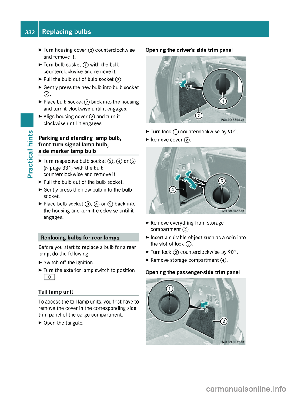
To access the tail lamp units, you first have to
remove the cover in the corresponding side
trim panel of the cargo compartment.
XOpen the tailgate.Opening the driver’s side trim panelXTurn lock : counterclockwise by 90°.XRemove cover ;.XRemove everything from storage
compartment ?.
XInsert a suitable object such as a coin into
the slot of lock =.
XTurn lock = counterclockwise by 90°.XRemove storage compartment ?.
Opening the passenger-side trim panel
332Replacing bulbsPractical hints
X164_AKB; 5; 31, en-USd2ureepe,Version: 2.11.8.12009-09-11T12:30:16+02:00 - Seite 332
Page 335 of 380
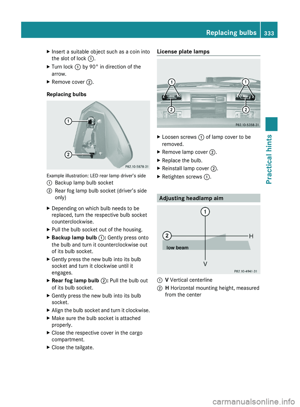
XInsert a suitable object such as a coin into
the slot of lock :.
XTurn lock : by 90° in direction of the
arrow.
XRemove cover ;.
Replacing bulbs
Example illustration: LED rear lamp driver’s side
:Backup lamp bulb socket;Rear fog lamp bulb socket (driver’s side
only)
XDepending on which bulb needs to be
replaced, turn the respective bulb socket
counterclockwise.
XPull the bulb socket out of the housing.XBackup lamp bulb :: Gently press onto
the bulb and turn it counterclockwise out
of its bulb socket.
XGently press the new bulb into its bulb
socket and turn it clockwise until it
engages.
XRear fog lamp bulb ;: Pull the bulb out
of its bulb socket.
XGently press the new bulb into its bulb
socket.
XAlign the bulb socket and turn it clockwise.XMake sure the bulb socket is attached
properly.
XClose the respective cover in the cargo
compartment.
XClose the tailgate.License plate lampsXLoosen screws : of lamp cover to be
removed.
XRemove lamp cover ;.XReplace the bulb.XReinstall lamp cover ;.XRetighten screws :.
Adjusting headlamp aim
:V Vertical centerline;H Horizontal mounting height, measured
from the center
Replacing bulbs333Practical hintsX164_AKB; 5; 31, en-USd2ureepe,Version: 2.11.8.12009-09-11T12:30:16+02:00 - Seite 333Z
Page 336 of 380
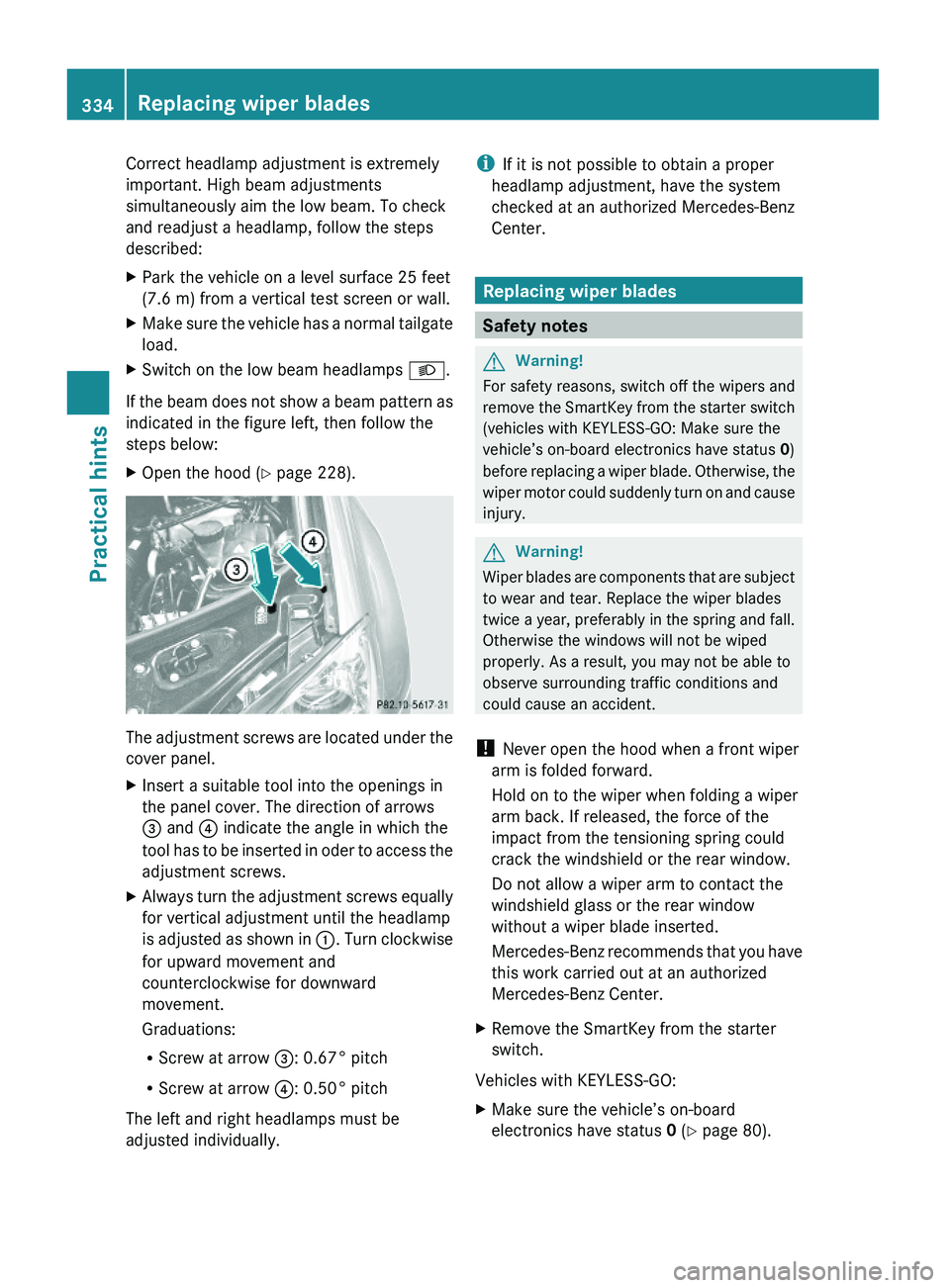
Correct headlamp adjustment is extremely
important. High beam adjustments
simultaneously aim the low beam. To check
and readjust a headlamp, follow the steps
described:
XPark the vehicle on a level surface 25 feet
(7.6 m) from a vertical test screen or wall.
XMake sure the vehicle has a normal tailgate
load.
XSwitch on the low beam headlamps L.
If the beam does not show a beam pattern as
indicated in the figure left, then follow the
steps below:
XOpen the hood (Y page 228).
The adjustment screws are located under the
cover panel.
XInsert a suitable tool into the openings in
the panel cover. The direction of arrows
= and ? indicate the angle in which the
tool has to be inserted in oder to access the
adjustment screws.
XAlways turn the adjustment screws equally
for vertical adjustment until the headlamp
is adjusted as shown in :. Turn clockwise
for upward movement and
counterclockwise for downward
movement.
Graduations:
RScrew at arrow =: 0.67° pitch
RScrew at arrow ?: 0.50° pitch
The left and right headlamps must be
adjusted individually.
iIf it is not possible to obtain a proper
headlamp adjustment, have the system
checked at an authorized Mercedes-Benz
Center.
Replacing wiper blades
Safety notes
GWarning!
For safety reasons, switch off the wipers and
remove the SmartKey from the starter switch
(vehicles with KEYLESS-GO: Make sure the
vehicle’s on-board electronics have status 0)
before replacing a wiper blade. Otherwise, the
wiper motor could suddenly turn on and cause
injury.
GWarning!
Wiper blades are components that are subject
to wear and tear. Replace the wiper blades
twice a year, preferably in the spring and fall.
Otherwise the windows will not be wiped
properly. As a result, you may not be able to
observe surrounding traffic conditions and
could cause an accident.
! Never open the hood when a front wiper
arm is folded forward.
Hold on to the wiper when folding a wiper
arm back. If released, the force of the
impact from the tensioning spring could
crack the windshield or the rear window.
Do not allow a wiper arm to contact the
windshield glass or the rear window
without a wiper blade inserted.
Mercedes-Benz recommends that you have
this work carried out at an authorized
Mercedes-Benz Center.
XRemove the SmartKey from the starter
switch.
Vehicles with KEYLESS-GO:
XMake sure the vehicle’s on-board
electronics have status 0 (Y page 80).
334Replacing wiper bladesPractical hints
X164_AKB; 5; 31, en-USd2ureepe,Version: 2.11.8.12009-09-11T12:30:16+02:00 - Seite 334
Page 338 of 380
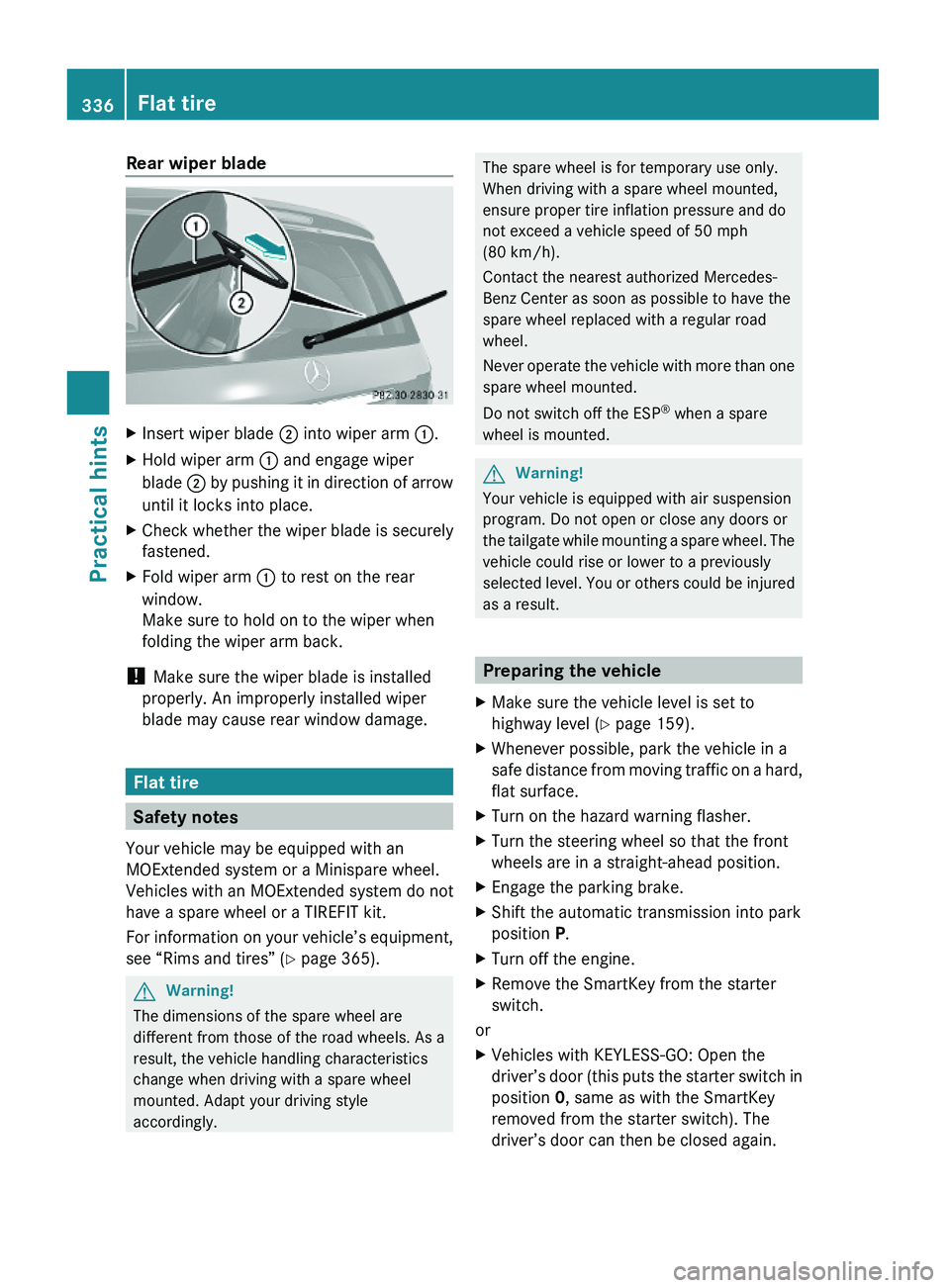
Rear wiper bladeXInsert wiper blade ; into wiper arm :.XHold wiper arm : and engage wiper
blade ; by pushing it in direction of arrow
until it locks into place.
XCheck whether the wiper blade is securely
fastened.
XFold wiper arm : to rest on the rear
window.
Make sure to hold on to the wiper when
folding the wiper arm back.
! Make sure the wiper blade is installed
properly. An improperly installed wiper
blade may cause rear window damage.
Flat tire
Safety notes
Your vehicle may be equipped with an
MOExtended system or a Minispare wheel.
Vehicles with an MOExtended system do not
have a spare wheel or a TIREFIT kit.
For information on your vehicle’s equipment,
see “Rims and tires” (Y page 365).
GWarning!
The dimensions of the spare wheel are
different from those of the road wheels. As a
result, the vehicle handling characteristics
change when driving with a spare wheel
mounted. Adapt your driving style
accordingly.
The spare wheel is for temporary use only.
When driving with a spare wheel mounted,
ensure proper tire inflation pressure and do
not exceed a vehicle speed of 50 mph
(80 km/h).
Contact the nearest authorized Mercedes-
Benz Center as soon as possible to have the
spare wheel replaced with a regular road
wheel.
Never operate the vehicle with more than one
spare wheel mounted.
Do not switch off the ESP® when a spare
wheel is mounted.
GWarning!
Your vehicle is equipped with air suspension
program. Do not open or close any doors or
the tailgate while mounting a spare wheel. The
vehicle could rise or lower to a previously
selected level. You or others could be injured
as a result.
Preparing the vehicle
XMake sure the vehicle level is set to
highway level (Y page 159).
XWhenever possible, park the vehicle in a
safe distance from moving traffic on a hard,
flat surface.
XTurn on the hazard warning flasher.XTurn the steering wheel so that the front
wheels are in a straight-ahead position.
XEngage the parking brake.XShift the automatic transmission into park
position P.
XTurn off the engine.XRemove the SmartKey from the starter
switch.
or
XVehicles with KEYLESS-GO: Open the
driver’s door (this puts the starter switch in
position 0, same as with the SmartKey
removed from the starter switch). The
driver’s door can then be closed again.
336Flat tirePractical hints
X164_AKB; 5; 31, en-USd2ureepe,Version: 2.11.8.12009-09-11T12:30:16+02:00 - Seite 336