2010 MERCEDES-BENZ E63AMG light
[x] Cancel search: lightPage 201 of 372
Parcel netsGWarning!
Parcel nets are intended for storing light-
weight items only, such as road maps, mail,
etc.
Heavy objects, objects with sharp edges, or
fragile objects may not be transported in the
parcel nets. In an accident, during hard
braking, or sudden maneuvers, they could be
thrown around inside the vehicle and cause
injury to vehicle occupants.
Parcel nets cannot protect transported goods
in the event of an accident.
Parcel nets are located:
Rin the front passenger footwell
Rbehind the rear armrest
Rat each side of the left and right trunk side
walls
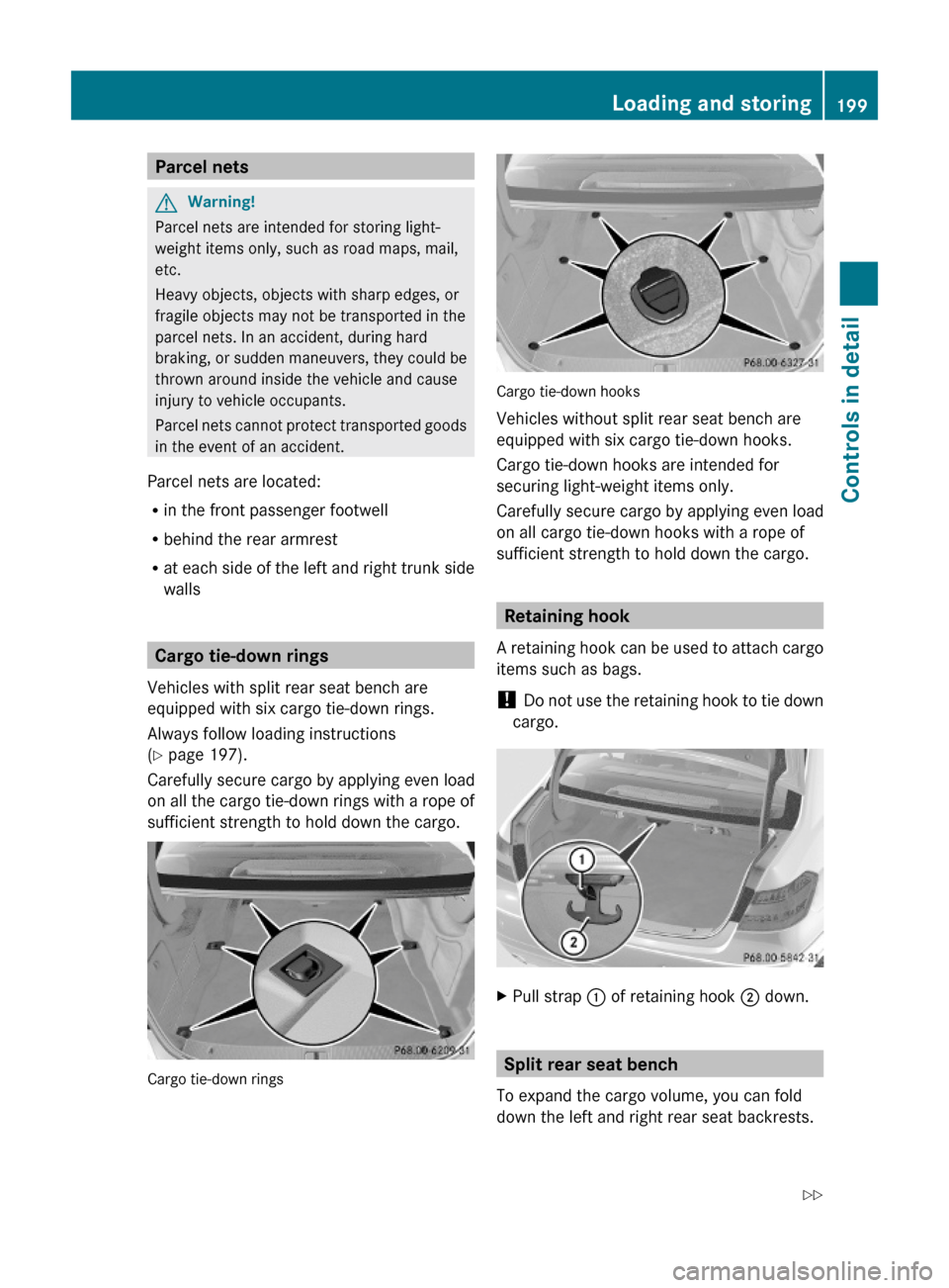
Cargo tie-down rings
Vehicles with split rear seat bench are
equipped with six cargo tie-down rings.
Always follow loading instructions
(Y page 197).
Carefully secure cargo by applying even load
on all the cargo tie-down rings with a rope of
sufficient strength to hold down the cargo.
Cargo tie-down rings
Cargo tie-down hooks
Vehicles without split rear seat bench are
equipped with six cargo tie-down hooks.
Cargo tie-down hooks are intended for
securing light-weight items only.
Carefully secure cargo by applying even load
on all cargo tie-down hooks with a rope of
sufficient strength to hold down the cargo.
Retaining hook
A retaining hook can be used to attach cargo
items such as bags.
! Do not use the retaining hook to tie down
cargo.
XPull strap : of retaining hook ; down.
Split rear seat bench
To expand the cargo volume, you can fold
down the left and right rear seat backrests.
Loading and storing199Controls in detail212_AKB; 2; 41, en-USd2ureepe,Version: 2.11.8.12009-07-17T09:14:21+02:00 - Seite 199Z
Page 205 of 372
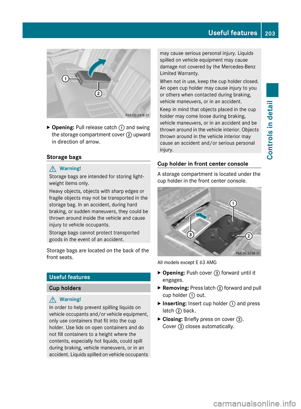
XOpening: Pull release catch : and swing
the storage compartment cover ; upward
in direction of arrow.
Storage bags
GWarning!
Storage bags are intended for storing light-
weight items only.
Heavy objects, objects with sharp edges or
fragile objects may not be transported in the
storage bag. In an accident, during hard
braking, or sudden maneuvers, they could be
thrown around inside the vehicle and cause
injury to vehicle occupants.
Storage bags cannot protect transported
goods in the event of an accident.
Storage bags are located on the back of the
front seats.
Useful features
Cup holders
GWarning!
In order to help prevent spilling liquids on
vehicle occupants and/or vehicle equipment,
only use containers that fit into the cup
holder. Use lids on open containers and do
not fill containers to a height where the
contents, especially hot liquids, could spill
during braking, vehicle maneuvers, or in an
accident. Liquids spilled on vehicle occupants
may cause serious personal injury. Liquids
spilled on vehicle equipment may cause
damage not covered by the Mercedes-Benz
Limited Warranty.
When not in use, keep the cup holder closed.
An open cup holder may cause injury to you
or others when contacted during braking,
vehicle maneuvers, or in an accident.
Keep in mind that objects placed in the cup
holder may come loose during braking,
vehicle maneuvers, or in an accident and be
thrown around in the vehicle interior. Objects
thrown around in the vehicle interior may
cause an accident and/or serious personal
injury.
Cup holder in front center console
A storage compartment is located under the
cup holder in the front center console.
All models except E 63 AMG
XOpening: Push cover = forward until it
engages.
XRemoving: Press latch ; forward and pull
cup holder : out.
XInserting: Insert cup holder : and press
latch ; back.
XClosing: Briefly press on cover =.
Cover = closes automatically.
Useful features203Controls in detail212_AKB; 2; 41, en-USd2ureepe,Version: 2.11.8.12009-07-17T09:14:21+02:00 - Seite 203Z
Page 208 of 372
Ashtrays
Center console ashtray
iA storage compartment is located under
the ashtray insert.
! The storage compartment is not heat-
proof. When smoking always make sure the
ashtray insert is present and properly
inserted.
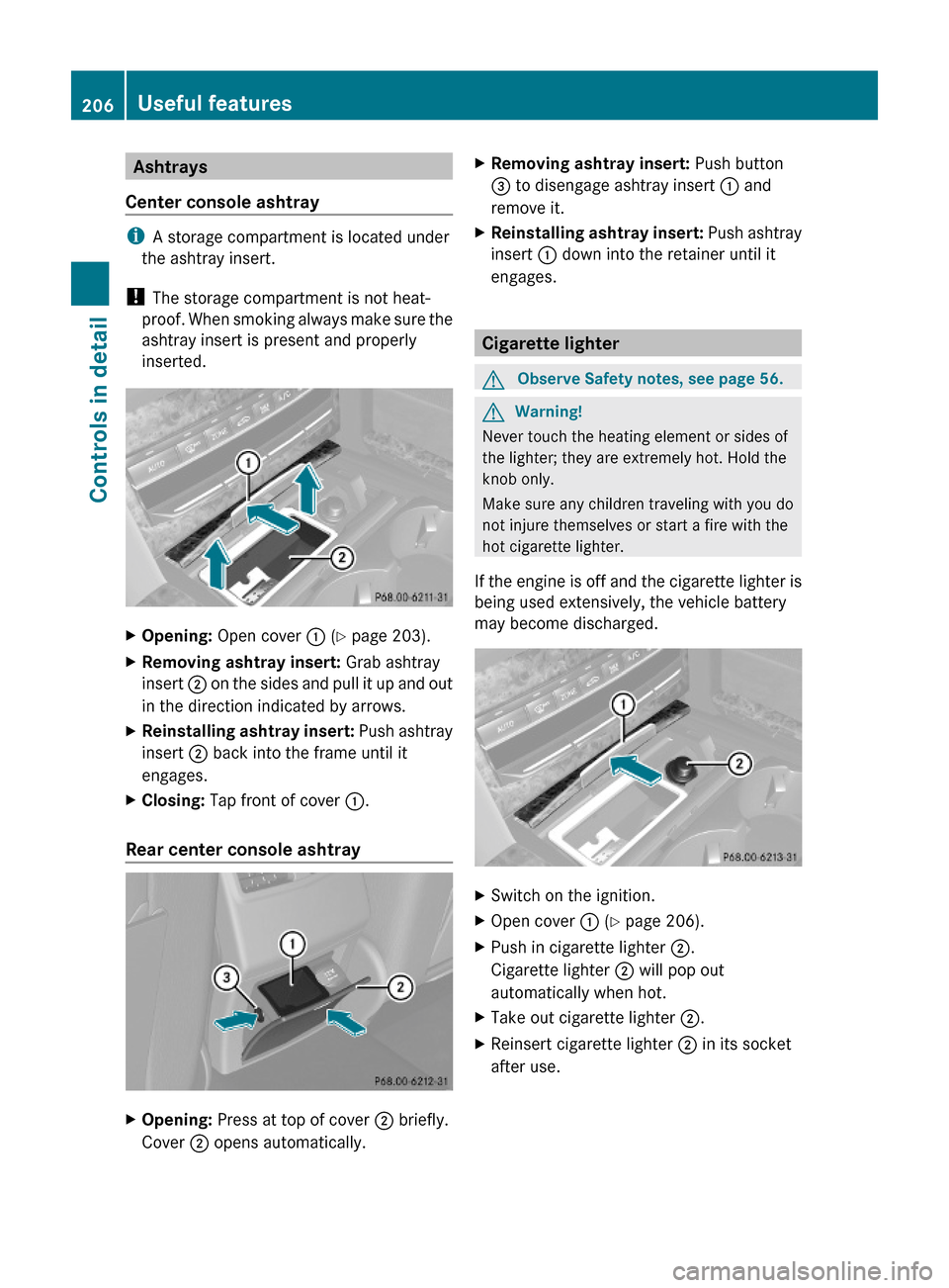
XOpening: Open cover : (Y page 203).XRemoving ashtray insert: Grab ashtray
insert ; on the sides and pull it up and out
in the direction indicated by arrows.
XReinstalling ashtray insert: Push ashtray
insert ; back into the frame until it
engages.
XClosing: Tap front of cover :.
Rear center console ashtray
XOpening: Press at top of cover ; briefly.
Cover ; opens automatically.
XRemoving ashtray insert: Push button
= to disengage ashtray insert : and
remove it.
XReinstalling ashtray insert: Push ashtray
insert : down into the retainer until it
engages.
Cigarette lighter
GObserve Safety notes, see page 56.GWarning!
Never touch the heating element or sides of
the lighter; they are extremely hot. Hold the
knob only.
Make sure any children traveling with you do
not injure themselves or start a fire with the
hot cigarette lighter.
If the engine is off and the cigarette lighter is
being used extensively, the vehicle battery
may become discharged.
XSwitch on the ignition.XOpen cover : (Y page 206).XPush in cigarette lighter ;.
Cigarette lighter ; will pop out
automatically when hot.
XTake out cigarette lighter ;.XReinsert cigarette lighter ; in its socket
after use.
206Useful featuresControls in detail
212_AKB; 2; 41, en-USd2ureepe,Version: 2.11.8.12009-07-17T09:14:21+02:00 - Seite 206
Page 215 of 372
When programming a garage door opener,
park vehicle outside the garage.
Do not run the engine while programming the
integrated remote control. Inhalation of
exhaust gas is hazardous to your health. All
exhaust gas contains carbon monoxide (CO),
and inhaling it can cause unconsciousness
and possible death.
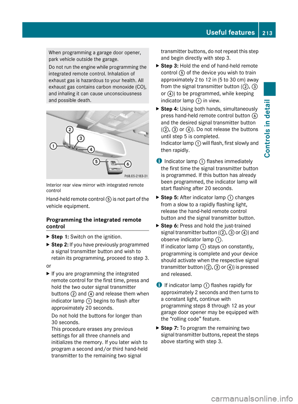
Interior rear view mirror with integrated remotecontrol
Hand-held remote control A is not part of the
vehicle equipment.
Programming the integrated remote
control
XStep 1: Switch on the ignition.XStep 2: If you have previously programmed
a signal transmitter button and wish to
retain its programming, proceed to step 3.
or
XIf you are programming the integrated
remote control for the first time, press and
hold the two outer signal transmitter
buttons ; and ? and release them when
indicator lamp : begins to flash after
approximately 20 seconds.
Do not hold the buttons for longer than
30 seconds.
This procedure erases any previous
settings for all three channels and
initializes the memory. If you later wish to
program a second and/or third hand-held
transmitter to the remaining two signal
transmitter buttons, do not repeat this step
and begin directly with step 3.
XStep 3: Hold the end of hand-held remote
control A of the device you wish to train
approximately 2 to 12 in (5 to 30 cm) away
from the signal transmitter button (;, =
or ?) to be programmed, while keeping
indicator lamp : in view.
XStep 4: Using both hands, simultaneously
press hand-held remote control button B
and the desired signal transmitter button
(;, = or ?). Do not release the buttons
until step 5 is completed.
Indicator lamp : will flash, first slowly and
then rapidly.
iIndicator lamp : flashes immediately
the first time the signal transmitter button
is programmed. If this button has already
been programmed, the indicator lamp will
start flashing after 20 seconds.
XStep 5: After indicator lamp : changes
from a slow to a rapidly flashing light,
release the hand-held remote control
button and the signal transmitter button.
XStep 6: Press and hold the just-trained
signal transmitter button (;, = or ?) and
observe indicator lamp :.
If indicator lamp : stays on constantly,
programming is complete and your device
should activate when the respective signal
transmitter button (;, = or ?) is pressed
and released.
iIf indicator lamp : flashes rapidly for
approximately 2 seconds and then turns to
a constant light, continue with
programming steps 8 through 12 as your
garage door opener may be equipped with
the “rolling code” feature.
XStep 7: To program the remaining two
signal transmitter buttons, repeat the steps
above starting with step 3.
Useful features213Controls in detail212_AKB; 2; 41, en-USd2ureepe,Version: 2.11.8.12009-07-17T09:14:21+02:00 - Seite 213Z
Page 216 of 372
Rolling code programming
To train a garage door opener (or other rolling
code devices) with the rolling code feature,
follow these instructions after completing the
“Programming” portion (steps 1 through 6) of
this text. For your convenience and to
complete the procedure faster, you might
want to have someone assist you.XStep 8: Locate the “training” button on the
garage door opener motor head unit.
i Exact location and color of the button may
vary by garage door opener brand.
Depending on manufacturer, the “training”
button may also be referred to as “learn” or
“smart” button. If there is difficulty locating
the transmitting button, refer to the garage
door opener Operator’s Manual.
XStep 9: Press the “training” button on the
garage door opener motor head unit.
The “training light” is activated.
You have 30 seconds to initiate the
following two steps.XStep 10: Return to the vehicle and firmly
press, hold for 2 seconds and release the
programmed signal transmitter button ( ;,
= or ?).XStep 11: Press, hold for 2 seconds and
release same signal transmitter button a
second time to complete the training
process.
i Some garage door openers (or other
rolling code equipped devices) may require
you to press, hold for 2 seconds and
release the same signal transmitter button
a third time to complete the training
process.
XStep 12: Confirm the garage door
operation by pressing the programmed
signal transmitter button ( ;, = or ?).XStep 13: To program the remaining two
signal transmitter buttons, repeat the steps
above starting with step 3.Gate operator/Canadian programming
Canadian radio-frequency laws require
transmitter signals to “time-out” (or quit)
after several seconds of transmission which
may not be long enough for the integrated
signal transmitter to pick up the signal during
programming. Similar to this Canadian law,
some U.S. gate operators are designed to
“time-out” in the same manner.
If you live in Canada or if you are having
difficulties programming a gate operator
(regardless of where you live) by using the
programming procedures, replace step 4 with
the following:XStep 4: Press and hold the signal
transmitter button ( ;, = or ?). Do not
release this button until it has been
successfully trained.XWhile still holding down the signal
transmitter button ( ;, = or ?), “cycle”
your hand-held remote control button B
as follows: Press and hold button B for
2 seconds, then release it for 2 seconds,
and again press and hold it for 2 seconds.
Repeat this sequence on the hand-held
remote control until the frequency signal
has been learned.
Upon successful training, indicator
lamp : will flash slowly and then rapidly
after several seconds.XProceed with programming step 5 and
step 6 to complete.
i Upon completion of programming the
integrated remote control, make sure you
retain the hand-held remote control that
came with the garage door opener, gate
operator or other device. You may need it
for use in other vehicles, for future
programming of an integrated remote
control, or simply for continued use as a
hand-held remote control to operate the
respective device in other situations.
214Useful featuresControls in detail
212_AKB; 2; 41, en-USd2ureepe,Version: 2.11.8.12009-07-17T09:14:21+02:00 - Seite 214
Page 224 of 372

The fuel filler flap is located on the right-hand
side of the vehicle towards the rear.
XTurn off the engine.
iLeaving the engine running and the fuel
filler cap open can cause the yellow engine
malfunction indicator lamp ; to
illuminate.
For more information, see also “Practical
hints” (Y page 310).
XRemove the SmartKey from the starter
switch.
KEYLESS-GO: Open the driver’s door. This
puts the starter switch in position 0, same
as with the SmartKey removed from the
starter switch. The driver’s door then can
be closed again.
XOpening: Press fuel filler flap : at the
point indicated by the arrow.
XTurn fuel filler cap ; counterclockwise.XTake off fuel filler cap ;.
! The fuel filler cap is tethered to the fuel
filler neck. Do not drop the cap. It could
damage the vehicle paint finish.
XPlace fuel filler cap ; in direction of arrow
into holder =.
XFully insert filler nozzle unit and refuel.XOnly fill your tank until the filler nozzle unit
cuts out – do not top off or overfill.
XClosing: Turn fuel filler cap ; clockwise
until it audibly engages.
iClose the fuel filler flap before locking the
vehicle. Otherwise the flap locking pin will
prevent closing the fuel filler flap.
XClose fuel filler flap :.
Low outside temperatures (diesel
engine)
! Do not fill the tank with gasoline. Do not
blend diesel fuel with gasoline or kerosene.
The fuel system and engine will otherwise
be damaged, which is not covered by the
Mercedes-Benz Limited Warranty.
To prevent malfunctions, diesel fuel with
improved cold flow characteristics is offered
in the winter months. Check with your fuel
retailer.
Check regularly and before a long trip
For information on quantities and
requirements of operating agents, see “Fuels,
coolants, lubricants, etc.” (Y page 359).
Check the following:
REngine oil level (Y page 224)
RTire inflation pressure (Y page 231)
RCoolant level (Y page 226)
RVehicle lighting (Y page 318)
RWasher system and headlamp cleaning
system (Y page 227)
RBrake fluid (Y page 227)
222At the gas stationOperation
212_AKB; 2; 41, en-USd2ureepe,Version: 2.11.8.12009-07-17T09:14:21+02:00 - Seite 222
Page 245 of 372

Do not allow your tires to wear down too far.
Adhesion properties on wet roads are sharply
reduced at tread depths of less than 1/8 in
(3 mm).
Treadwear indicators (TWI) are required by
law. These indicators are located in six places
on the tread circumference and become
visible at a tread depth of approximately1/16 in (1.6 mm), at which point the tire is
considered worn and should be replaced.
The recommended minimum tire tread depth
for summer tires is 1/8 in (3 mm). The
recommended minimum tire tread depth for
winter tires is 1/6 in (4 mm).
Treadwear indicator : appears as a solid
band across the tread.
Storing tires
! Keep unmounted tires in a cool, dry place
with as little exposure to light as possible.
Protect tires from contact with oil, grease
and fuels.
Cleaning tires
! Never use a round nozzle to power wash
tires. The intense jet of water can result in
damage to the tire.
Always replace a damaged tire.
Uniform Tire Quality Grading
Standards
The Uniform Tire Quality Grading is a U.S.
Government requirement designed to give
drivers consistent and reliable information
regarding tire performance. Tire
manufacturers are required to grade tires
based on three performance factors:
treadwear :, traction ;, and temperature
resistance =. Although not a Government of
Canada requirement, all tires made for sale in
North America have these grades branded on
the sidewall.
iFor illustration purposes only. Actual data
on tires are specific to each vehicle and
may vary from data shown in above
illustration.
Quality grades can be found, where
applicable, on the tire sidewall between tread
shoulder and maximum section width. For
example:
TreadwearTractionTemperature200AAA
All passenger car tires must conform to
federal safety requirements in addition to
these grades.
Treadwear
The treadwear grade is a comparative rating
based on the wear rate of the tire when tested
under controlled conditions on a specified
U.S. Government test course. For example, a
Tires and wheels243Operation212_AKB; 2; 41, en-USd2ureepe,Version: 2.11.8.12009-07-17T09:14:21+02:00 - Seite 243Z
Page 248 of 372

Tire size designation, load and speed
rating:Tire width;Aspect ratio in %=Radial tire code?Rim diameterALoad index BSpeed symbol
iFor illustration purposes only. Actual data
on tires are specific to each vehicle and
may vary from data shown in above
illustration.
General: Depending on the design standards
used, the tire size molded into the sidewall
may have no letter or a letter preceding the
tire size designation.
No letter preceding the size designation (as
illustrated above): Passenger car tire based
on European design standards.
Letter “P” preceding the size designation:
Passenger car tire based on U.S. design
standards.
Letter “LT” preceding the size designation:
Light Truck tire based on U.S. design
standards.
Letter “T” preceding the size designation:
Temporary spare tires which are high
pressure compact spares designed for
temporary emergency use only.
Tire width
Tire width : indicates the nominal tire width
in millimeters.
Aspect ratio
Aspect ratio ; is the dimensional
relationship between tire section height and
section width and is expressed in percentage.
The aspect ratio is arrived at by dividing
section height by section width.
Tire code
Tire code = indicates the tire construction
type. The “R” stands for radial tire type. Letter
“D” means diagonal or bias ply construction;
letter “B” means belted-bias ply construction.
At the tire manufacturer’s option, any tire
with a speed capability above 149 mph
(240 km/h) can include a “ZR” in the size
designation (for example: 245/40 ZR 18). For
additional information, see “Tire speed
rating” (Y page 247).
Rim diameter
Rim diameter ? is the diameter of the bead
seat, not the diameter of the rim edge. The
rim diameter is indicated in inches (in).
Load index
GWarning!
The tire load rating must always be at least
half of the GAWR of your vehicle. Otherwise,
tire failure may be the result which may cause
an accident and/or serious injury to you or
others.
Always replace rims and tires with the same
designation, manufacturer and type as shown
on the original part.
GWarning!
Do not overload the tires by exceeding the
specified load limit as indicated on the Tire
and Loading Information placard on the
driver’s door B-pillar. Overloading the tires
can overheat them, possibly causing a
blowout. Overloading the tires can also result
in handling or steering problems, or brake
failure.
Load index A is a numerical code associated
with the maximum load a tire can support.
246Tires and wheelsOperation
212_AKB; 2; 41, en-USd2ureepe,Version: 2.11.8.12009-07-17T09:14:21+02:00 - Seite 246