2010 MERCEDES-BENZ E63AMG light
[x] Cancel search: lightPage 320 of 372
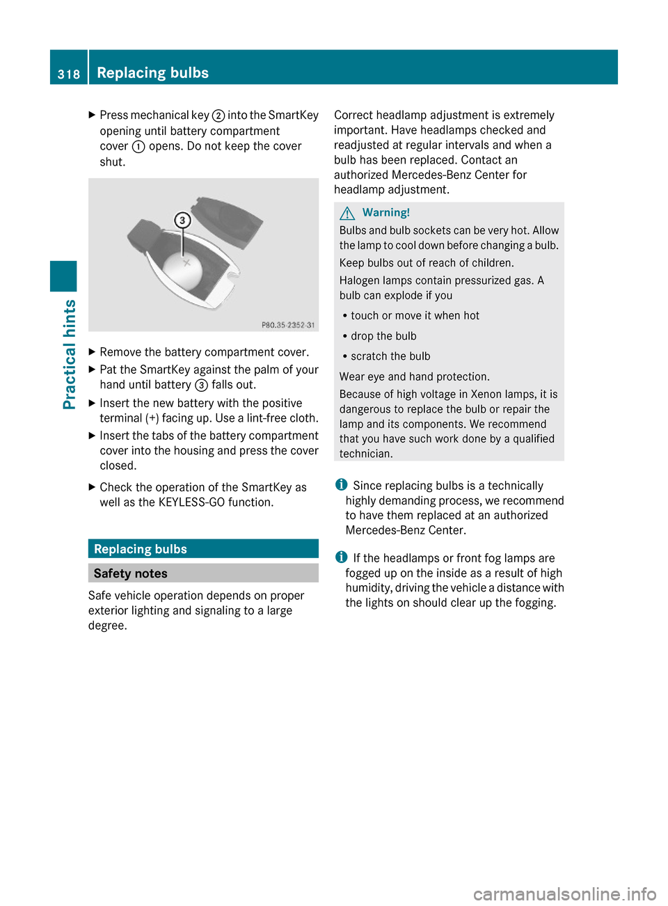
XPress mechanical key ; into the SmartKey
opening until battery compartment
cover : opens. Do not keep the cover
shut.
XRemove the battery compartment cover.XPat the SmartKey against the palm of your
hand until battery = falls out.
XInsert the new battery with the positive
terminal (+) facing up. Use a lint-free cloth.
XInsert the tabs of the battery compartment
cover into the housing and press the cover
closed.
XCheck the operation of the SmartKey as
well as the KEYLESS-GO function.
Replacing bulbs
Safety notes
Safe vehicle operation depends on proper
exterior lighting and signaling to a large
degree.
Correct headlamp adjustment is extremely
important. Have headlamps checked and
readjusted at regular intervals and when a
bulb has been replaced. Contact an
authorized Mercedes-Benz Center for
headlamp adjustment.
GWarning!
Bulbs and bulb sockets can be very hot. Allow
the lamp to cool down before changing a bulb.
Keep bulbs out of reach of children.
Halogen lamps contain pressurized gas. A
bulb can explode if you
Rtouch or move it when hot
Rdrop the bulb
Rscratch the bulb
Wear eye and hand protection.
Because of high voltage in Xenon lamps, it is
dangerous to replace the bulb or repair the
lamp and its components. We recommend
that you have such work done by a qualified
technician.
iSince replacing bulbs is a technically
highly demanding process, we recommend
to have them replaced at an authorized
Mercedes-Benz Center.
iIf the headlamps or front fog lamps are
fogged up on the inside as a result of high
humidity, driving the vehicle a distance with
the lights on should clear up the fogging.
318Replacing bulbsPractical hints
212_AKB; 2; 41, en-USd2ureepe,Version: 2.11.8.12009-07-17T09:14:21+02:00 - Seite 318
Page 321 of 372
Bulbs
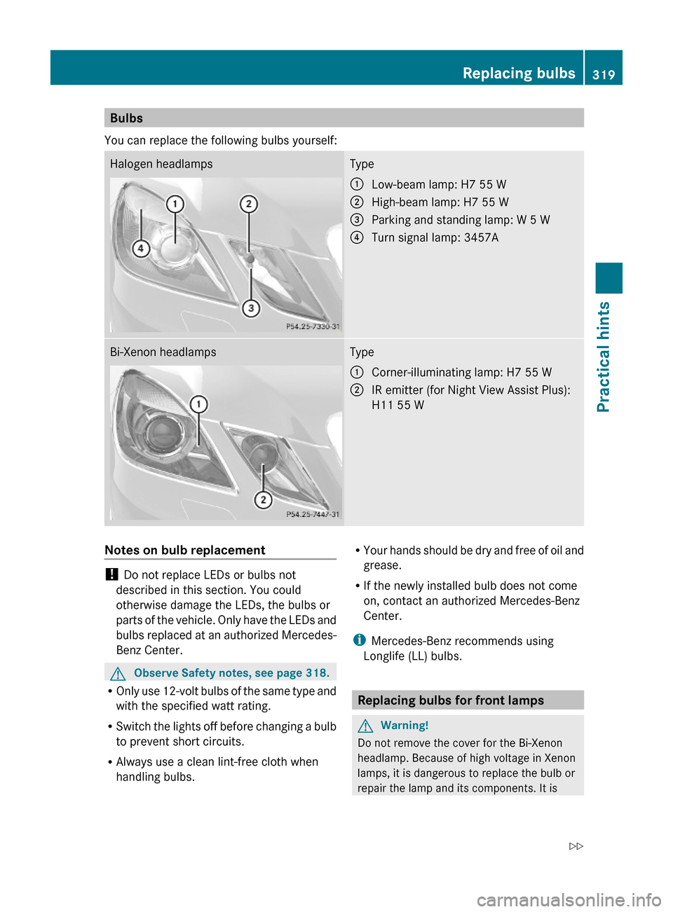
You can replace the following bulbs yourself:
Halogen headlampsType:Low-beam lamp: H7 55 W;High-beam lamp: H7 55 W=Parking and standing lamp: W 5 W?Turn signal lamp: 3457ABi-Xenon headlampsType:Corner-illuminating lamp: H7 55 W;IR emitter (for Night View Assist Plus):
H11 55 W
Notes on bulb replacement
! Do not replace LEDs or bulbs not
described in this section. You could
otherwise damage the LEDs, the bulbs or
parts of the vehicle. Only have the LEDs and
bulbs replaced at an authorized Mercedes-
Benz Center.
GObserve Safety notes, see page 318.
ROnly use 12-volt bulbs of the same type and
with the specified watt rating.
RSwitch the lights off before changing a bulb
to prevent short circuits.
RAlways use a clean lint-free cloth when
handling bulbs.
RYour hands should be dry and free of oil and
grease.
RIf the newly installed bulb does not come
on, contact an authorized Mercedes-Benz
Center.
iMercedes-Benz recommends using
Longlife (LL) bulbs.
Replacing bulbs for front lamps
GWarning!
Do not remove the cover for the Bi-Xenon
headlamp. Because of high voltage in Xenon
lamps, it is dangerous to replace the bulb or
repair the lamp and its components. It is
Replacing bulbs319Practical hints212_AKB; 2; 41, en-USd2ureepe,Version: 2.11.8.12009-07-17T09:14:21+02:00 - Seite 319Z
Page 324 of 372
XTurn the bulb counterclockwise with light
pressure and pull it out of bulb socket :.
XInsert the new bulb into bulb socket : and
turn the bulb clockwise.
XInsert bulb socket : into the housing and
turn it clockwise.
XDriver’s side only: Fix the washer fluid
reservoir (Y page 320).
Replacing wiper blades
Safety notes
GWarning!
For safety reasons, switch off the wipers and
remove the SmartKey from the starter switch
(vehicles with KEYLESS-GO: Make sure the
vehicle’s on-board electronics have status 0)
before replacing a wiper blade. Otherwise, the
wiper motor could suddenly turn on and cause
injury.
GWarning!
Wiper blades are components that are subject
to wear and tear. Replace the wiper blades
twice a year, preferably in the spring and fall.
Otherwise the windshield will not be wiped
properly. As a result, you may not be able to
observe surrounding traffic conditions and
could cause an accident.
! Never open the hood when a wiper arm is
folded forward.
Hold on to the wiper when folding a wiper
arm back. If released, the force of the
impact from the tensioning spring could
crack the windshield.
Do not allow a wiper arm to contact the
windshield glass without a wiper blade
inserted.
Mercedes-Benz recommends that you have
this work carried out at an authorized
Mercedes-Benz Center.
XRemove the SmartKey from the starter
switch.
Vehicles with KEYLESS-GO:XMake sure the vehicle’s on-board
electronics have status 0 (Y page 86).
Removing wiper blades
! Do not pull on the wiper blade inserts.
They could tear.
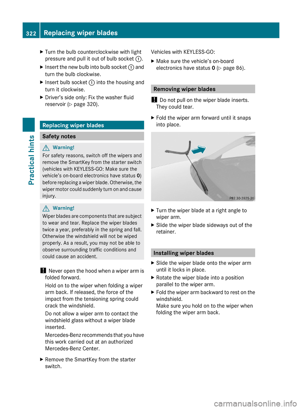
XFold the wiper arm forward until it snaps
into place.
XTurn the wiper blade at a right angle to
wiper arm.
XSlide the wiper blade sideways out of the
retainer.
Installing wiper blades
XSlide the wiper blade onto the wiper arm
until it locks in place.
XRotate the wiper blade into a position
parallel to the wiper arm.
XFold the wiper arm backward to rest on the
windshield.
Make sure you hold on to the wiper when
folding the wiper arm back.
322Replacing wiper bladesPractical hints
212_AKB; 2; 41, en-USd2ureepe,Version: 2.11.8.12009-07-17T09:14:21+02:00 - Seite 322
Page 326 of 372
iVehicles without spare wheel are not
factory-equipped with the tools required for
a wheel change such as a jack or a wheel
wrench. Some tools required for a wheel
change are specific to your vehicle.
Contact an authorized Mercedes-Benz
Center to obtain the tools approved for
your vehicle. This section describes the
wheel change using the tools approved and
recommended for your vehicle.
Lifting the vehicleGWarning!
When jacking up the vehicle, only use the jack
which has been specifically approved by
Mercedes-Benz for your vehicle.
The jack is designed exclusively for jacking up
the vehicle at the jack take-up brackets built
into both sides of the vehicle. Make sure the
jack arm is fully seated in the jack take-up
bracket. The jack must always be vertical
when in use, especially on inclines or
declines.
The jack is intended only for lifting the vehicle
briefly for wheel changes. It is not suited for
performing maintenance work under the
vehicle. To help avoid personal injury, use the
jack only to lift the vehicle during a wheel
change.
Never get beneath the vehicle while it is
supported by the jack. Keep hands and feet
away from the area under the lifted vehicle.
Always lower the vehicle onto sufficient
capacity jackstands before working under the
vehicle.
Always engage the parking brake firmly and
block the wheels with wheel chocks or other
sizeable objects before raising the vehicle
with the jack. Do not disengage the parking
brake while the vehicle is raised.
Make sure that the ground on which the
vehicle is standing and where you place the
jack is solid, level and not slippery. If
necessary, use a large underlay. On slippery
surfaces, such as tiled floors, you should use
a non-slip underlay, for example a rubber mat.
Do not use wooden blocks or similar objects
to support the jack. Otherwise the jack may
not be able to achieve its load-bearing
capacity if it is not at its full height.
Never start the engine when the vehicle is
raised.
Also observe the notes on the jack.XPrevent the vehicle from rolling away by
blocking wheels with wheel chocks or other
sizeable objects.
When your vehicle is equipped with a wheel
chock, it is included with the vehicle tool kit
( Y page 268). For information on setting up
the collapsible wheel chock, see
( Y page 270).
When changing a wheel on a level surface:
XPlace a wheel chock or other sizeable
object in front of and another wheel chock
or other sizeable object behind the wheel
that is diagonally opposite to the wheel
being changed.
Always try lifting the vehicle using the jack on
a level surface. However, should
circumstances require you to do so on a hill:
XPlace wheel chocks or other sizeable
objects on the downhill side in front of both
wheels on the side opposite to the side on
which the wheel is to be changed.GWarning!
Only jack up the vehicle on level ground or on
slight inclines/declines. Otherwise, the
vehicle could fall off the jack and injure you or
others.
324Flat tirePractical hints
212_AKB; 2; 41, en-USd2ureepe,Version: 2.11.8.12009-07-17T09:14:21+02:00 - Seite 324
Page 329 of 372
XGuide the spare wheel onto the alignment
bolt and push it on.
XInsert the wheel bolts and tighten them
slightly.
XUnscrew the alignment bolt.XInstall the last wheel bolt and tighten it
slightly.
XVehicles with spare wheel with
collapsible tire: Continue the procedure
by following the instructions under
“Inflating the collapsible tire”
(Y page 327) and then “Lowering the
vehicle” (Y page 328).
or
XVehicles with Minispare wheel: Continue
the procedure by following the instructions
under “Lowering the vehicle”
(Y page 328).
Inflating the collapsible tire
GWarning!
Inflate collapsible tire only after the wheel is
properly attached.
Inflate the collapsible tire using the electric
air pump before lowering the vehicle.
GWarning!
Observe safety instructions on air pump label.
! Do not lower the vehicle before inflating
the collapsible tire. Otherwise the rim may
be damaged.
Your vehicle may be equipped with either of
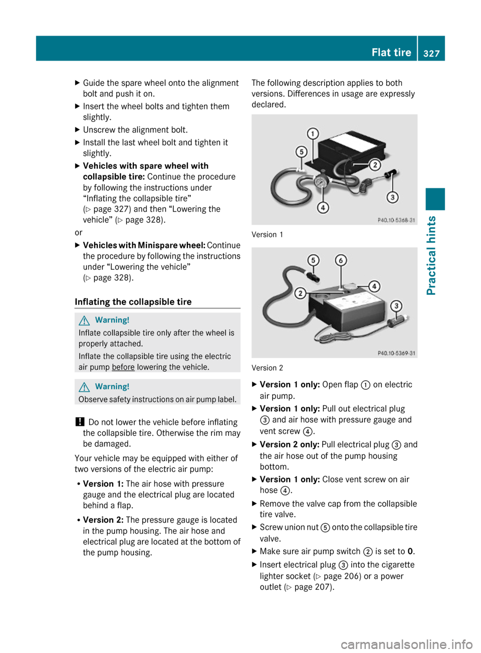
two versions of the electric air pump:
RVersion 1: The air hose with pressure
gauge and the electrical plug are located
behind a flap.
RVersion 2: The pressure gauge is located
in the pump housing. The air hose and
electrical plug are located at the bottom of
the pump housing.
The following description applies to both
versions. Differences in usage are expressly
declared.
Version 1
Version 2
XVersion 1 only: Open flap : on electric
air pump.
XVersion 1 only: Pull out electrical plug
= and air hose with pressure gauge and
vent screw ?.
XVersion 2 only: Pull electrical plug = and
the air hose out of the pump housing
bottom.
XVersion 1 only: Close vent screw on air
hose ?.
XRemove the valve cap from the collapsible
tire valve.
XScrew union nut A onto the collapsible tire
valve.
XMake sure air pump switch ; is set to 0.XInsert electrical plug = into the cigarette
lighter socket (Y page 206) or a power
outlet (Y page 207).
Flat tire327Practical hints212_AKB; 2; 41, en-USd2ureepe,Version: 2.11.8.12009-07-17T09:14:21+02:00 - Seite 327Z
Page 333 of 372
Version 1
Version 2
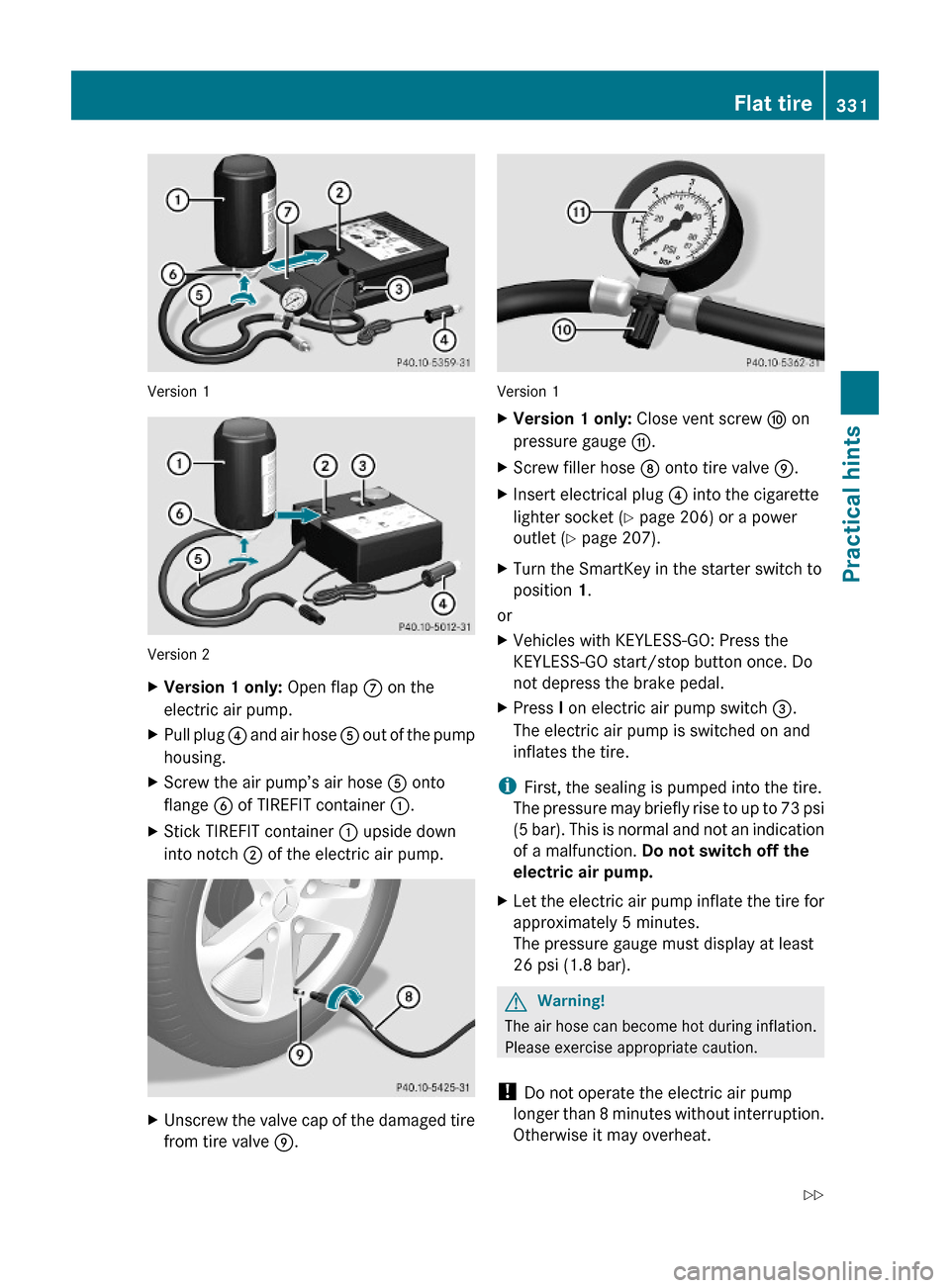
XVersion 1 only: Open flap C on the
electric air pump.
XPull plug ? and air hose A out of the pump
housing.
XScrew the air pump’s air hose A onto
flange B of TIREFIT container :.
XStick TIREFIT container : upside down
into notch ; of the electric air pump.
XUnscrew the valve cap of the damaged tire
from tire valve E.
Version 1
XVersion 1 only: Close vent screw F on
pressure gauge G.
XScrew filler hose D onto tire valve E.XInsert electrical plug ? into the cigarette
lighter socket (Y page 206) or a power
outlet (Y page 207).
XTurn the SmartKey in the starter switch to
position 1.
or
XVehicles with KEYLESS-GO: Press the
KEYLESS-GO start/stop button once. Do
not depress the brake pedal.
XPress I on electric air pump switch =.
The electric air pump is switched on and
inflates the tire.
iFirst, the sealing is pumped into the tire.
The pressure may briefly rise to up to 73 psi
(5 bar). This is normal and not an indication
of a malfunction. Do not switch off the
electric air pump.
XLet the electric air pump inflate the tire for
approximately 5 minutes.
The pressure gauge must display at least
26 psi (1.8 bar).
GWarning!
The air hose can become hot during inflation.
Please exercise appropriate caution.
! Do not operate the electric air pump
longer than 8 minutes without interruption.
Otherwise it may overheat.
Flat tire331Practical hints212_AKB; 2; 41, en-USd2ureepe,Version: 2.11.8.12009-07-17T09:14:21+02:00 - Seite 331Z
Page 357 of 372
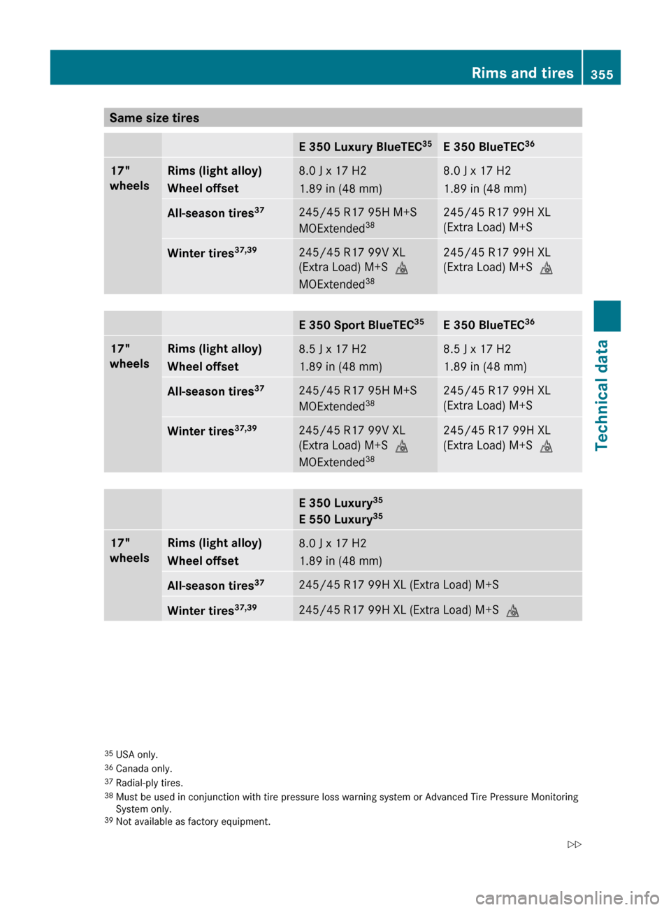
Same size tiresE 350 Luxury BlueTEC35E 350 BlueTEC3617"
wheelsRims (light alloy)
Wheel offset8.0 J x 17 H2
1.89 in (48 mm)8.0 J x 17 H2
1.89 in (48 mm)All-season tires 37245/45 R17 95H M+S
MOExtended 38245/45 R17 99H XL
(Extra Load) M+SWinter tires 37,39245/45 R17 99V XL
(Extra Load) M+S i
MOExtended 38245/45 R17 99H XL
(Extra Load) M+S iE 350 Sport BlueTEC 35E 350 BlueTEC3617"
wheelsRims (light alloy)
Wheel offset8.5 J x 17 H2
1.89 in (48 mm)8.5 J x 17 H2
1.89 in (48 mm)All-season tires 37245/45 R17 95H M+S
MOExtended 38245/45 R17 99H XL
(Extra Load) M+SWinter tires 37,39245/45 R17 99V XL
(Extra Load) M+S i
MOExtended 38245/45 R17 99H XL
(Extra Load) M+S iE 350 Luxury35
E 550 Luxury 3517"
wheelsRims (light alloy)
Wheel offset8.0 J x 17 H2
1.89 in (48 mm)All-season tires 37245/45 R17 99H XL (Extra Load) M+SWinter tires37,39245/45 R17 99H XL (Extra Load) M+S
i35
USA only.
36 Canada only.
37 Radial-ply tires.
38 Must be used in conjunction with tire pressure loss warning system or Advanced Tire Pressure Monitoring
System only.
39 Not available as factory equipment.Rims and tires355Technical data212_AKB; 2; 41, en-USd2ureepe,Version: 2.11.8.12009-07-17T09:14:21+02:00 - Seite 355Z
Page 358 of 372
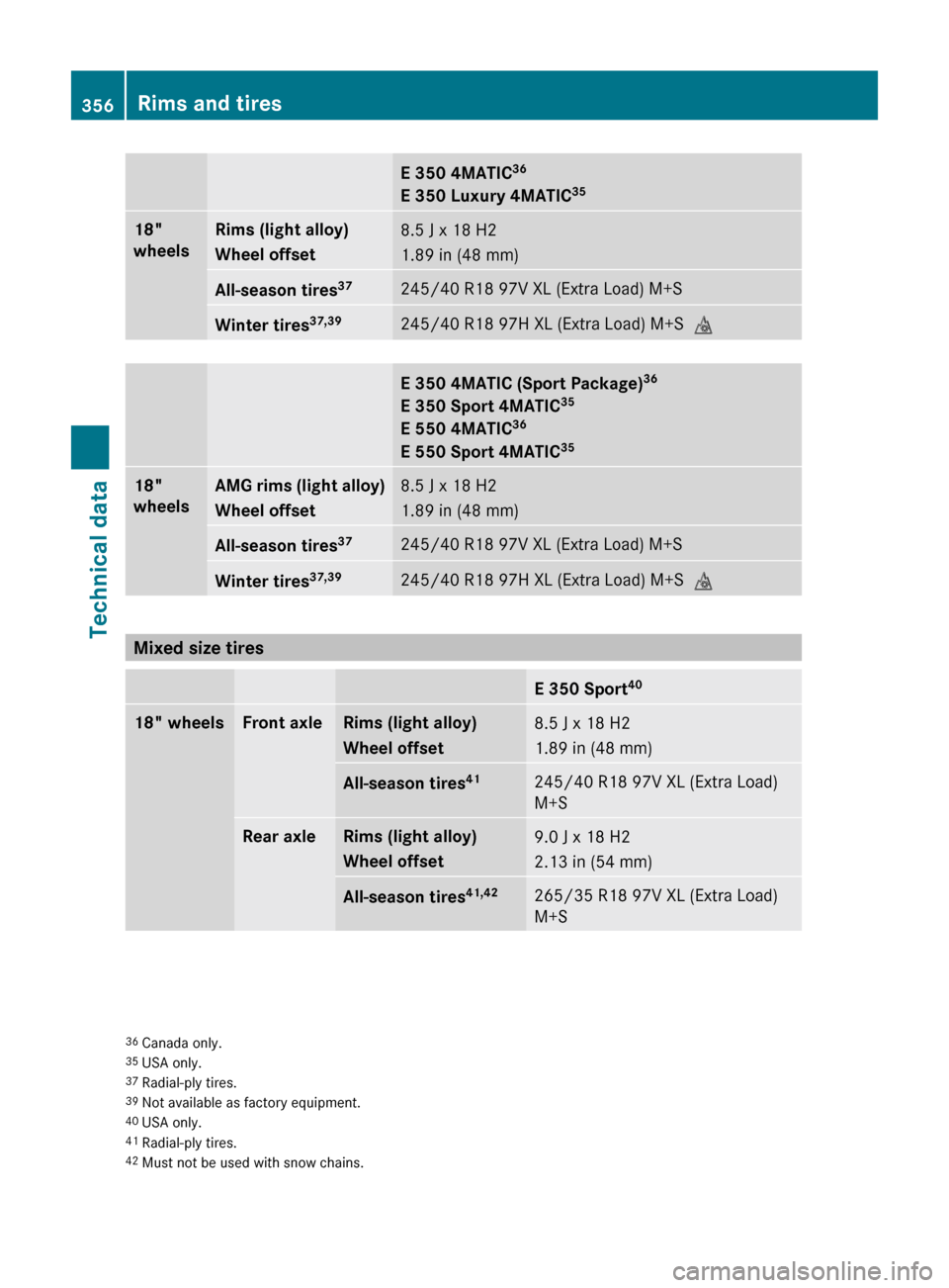
E 350 4MATIC36
E 350 Luxury 4MATIC 3518"
wheelsRims (light alloy)
Wheel offset8.5 J x 18 H2
1.89 in (48 mm)All-season tires 37245/40 R18 97V XL (Extra Load) M+SWinter tires37,39245/40 R18 97H XL (Extra Load) M+S
iE 350 4MATIC (Sport Package)36
E 350 Sport 4MATIC 35
E 550 4MATIC 36
E 550 Sport 4MATIC 3518"
wheelsAMG rims (light alloy)
Wheel offset8.5 J x 18 H2
1.89 in (48 mm)All-season tires 37245/40 R18 97V XL (Extra Load) M+SWinter tires37,39245/40 R18 97H XL (Extra Load) M+S
i
Mixed size tires
E 350 Sport4018" wheelsFront axleRims (light alloy)
Wheel offset8.5 J x 18 H2
1.89 in (48 mm)All-season tires 41245/40 R18 97V XL (Extra Load)
M+SRear axleRims (light alloy)
Wheel offset9.0 J x 18 H2
2.13 in (54 mm)All-season tires 41,42265/35 R18 97V XL (Extra Load)
M+S36 Canada only.
35 USA only.
37 Radial-ply tires.
39 Not available as factory equipment.
40 USA only.
41 Radial-ply tires.
42 Must not be used with snow chains.356Rims and tiresTechnical data
212_AKB; 2; 41, en-USd2ureepe,Version: 2.11.8.12009-07-17T09:14:21+02:00 - Seite 356