2010 MERCEDES-BENZ CLS63AMG ECU
[x] Cancel search: ECUPage 228 of 308

Before placing the jack back into the vehicle
tool kit:
X
Fully collapse the jack.
X Fold in the crank handle (storage position). Spare wheel
G
Observe Safety notes, see page 271.
The spare wheel is located in the space
underneath the trunk floor.
X Removing: Open the trunk (Y page 71).
X Lift the trunk floor using the floor handle.
X Engage the floor handle on the upper trunk
lip.
! To prevent damage, always disengage the
floor handle from the upper trunk lip and
lower the trunk floor before closing the
trunk.
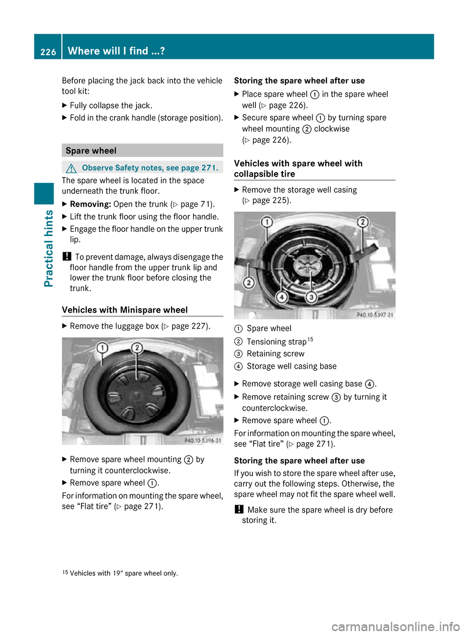
Vehicles with Minispare wheel X
Remove the luggage box ( Y page 227).X
Remove spare wheel mounting ; by
turning it counterclockwise.
X Remove spare wheel :.
For information on mounting the spare wheel,
see “Flat tire” ( Y page 271). Storing the spare wheel after use
X
Place spare wheel : in the spare wheel
well (Y page 226).
X Secure spare wheel : by turning spare
wheel mounting ; clockwise
(Y page 226).
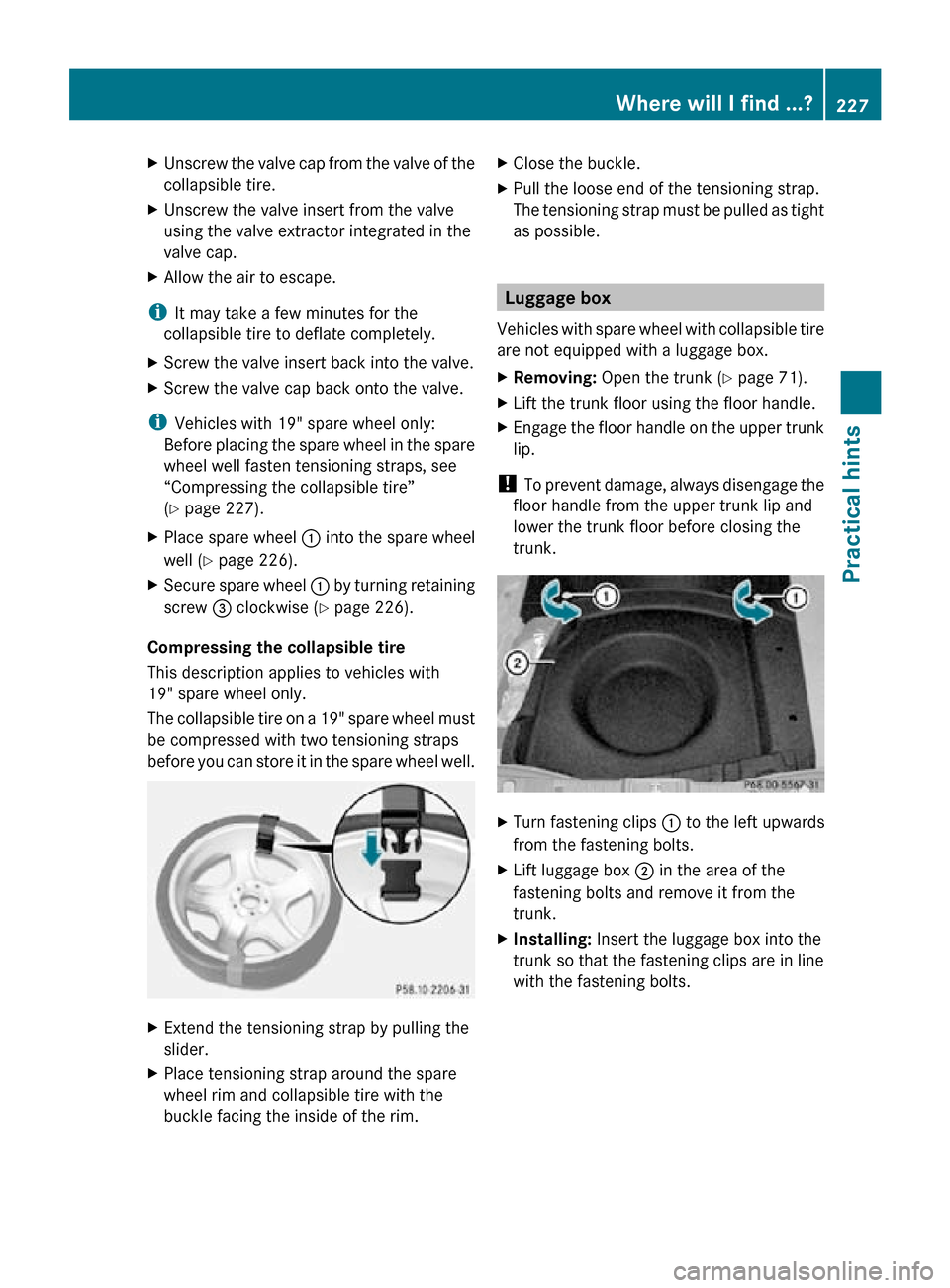
Vehicles with spare wheel with
collapsible tire X
Remove the storage well casing
(Y page 225). :
Spare wheel
; Tensioning strap 15
= Retaining screw
? Storage well casing base
X Remove storage well casing base ?.
X Remove retaining screw = by turning it
counterclockwise.
X Remove spare wheel :.
For information on mounting the spare wheel,
see “Flat tire” ( Y page 271).
Storing the spare wheel after use
If you wish to store the spare wheel after use,
carry out the following steps. Otherwise, the
spare wheel may not fit the spare wheel well.
! Make sure the spare wheel is dry before
storing it.
15 Vehicles with 19" spare wheel only. 226
Where will I find ...?Practical hints
219_AKB; 4; 54, en-US
d2ureepe,
Version: 2.11.8.1 2009-05-11T16:21:02+02:00 - Seite 226
Page 229 of 308

X
Unscrew the valve cap from the valve of the
collapsible tire.
X Unscrew the valve insert from the valve
using the valve extractor integrated in the
valve cap.
X Allow the air to escape.
i It may take a few minutes for the
collapsible tire to deflate completely.
X Screw the valve insert back into the valve.
X Screw the valve cap back onto the valve.
i Vehicles with 19" spare wheel only:
Before placing the spare wheel in the spare
wheel well fasten tensioning straps, see
“Compressing the collapsible tire”
(Y page 227).
X Place spare wheel : into the spare wheel
well (Y page 226).
X Secure spare wheel : by turning retaining
screw = clockwise (Y page 226).
Compressing the collapsible tire
This description applies to vehicles with
19" spare wheel only.
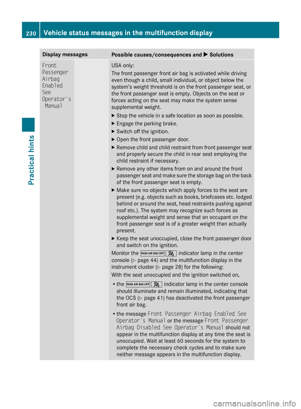
The collapsible tire on a 19" spare wheel must
be compressed with two tensioning straps
before you can store it in the spare wheel well. X
Extend the tensioning strap by pulling the
slider.
X Place tensioning strap around the spare
wheel rim and collapsible tire with the
buckle facing the inside of the rim. X
Close the buckle.
X Pull the loose end of the tensioning strap.
The tensioning strap must be pulled as tight
as possible. Luggage box
Vehicles with spare wheel with collapsible tire
are not equipped with a luggage box.
X Removing: Open the trunk (Y page 71).
X Lift the trunk floor using the floor handle.
X Engage the floor handle on the upper trunk
lip.
! To prevent damage, always disengage the
floor handle from the upper trunk lip and
lower the trunk floor before closing the
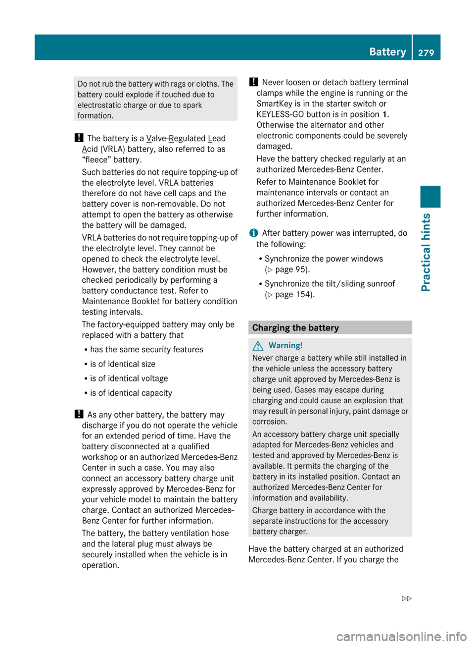
trunk. X
Turn fastening clips : to the left upwards
from the fastening bolts.
X Lift luggage box ; in the area of the
fastening bolts and remove it from the
trunk.
X Installing: Insert the luggage box into the
trunk so that the fastening clips are in line
with the fastening bolts. Where will I find ...?
227Practical hints
219_AKB; 4; 54, en-US
d2ureepe, Version: 2.11.8.1 2009-05-11T16:21:02+02:00 - Seite 227 Z
Page 232 of 308

Display messages
Possible causes/consequences and
X SolutionsFront
Passenger
Airbag
Enabled
See
Operator’s
Manual USA only:
The front passenger front air bag is activated while driving
even though a child, small individual, or object below the
system’s weight threshold is on the front passenger seat, or
the front passenger seat is empty. Objects on the seat or
forces acting on the seat may make the system sense
supplemental weight.
X
Stop the vehicle in a safe location as soon as possible.
X Engage the parking brake.
X Switch off the ignition.
X Open the front passenger door.
X Remove child and child restraint from front passenger seat
and properly secure the child in rear seat employing the
child restraint if necessary.
X Remove any other items from on and around the front
passenger
seat and make sure the storage bag on the back
of the front passenger seat is empty.
X Make sure no objects which apply forces to the seat are
present
(e.g. objects such as books, briefcases etc. lodged
behind or around the seat, head restraints pushing against
roof etc.). The system may recognize such forces as
supplemental weight and sense that an occupant on the
front passenger seat is of a greater weight than actually
present.
X Keep the seat unoccupied, close the front passenger door
and switch on the ignition.
Monitor the 04 indicator lamp in the center
console (Y page 44) and the multifunction display in the
instrument cluster
(Y page 28) for the following:
With the seat unoccupied and the ignition switched on,
R the 04 indicator lamp in the center console
should illuminate and remain illuminated, indicating that
the OCS (Y page 41) has deactivated the front passenger
front air bag.
R the message Front Passenger Airbag Enabled See
Operator’s Manual or the message Front Passenger
Airbag Disabled See Operator’s Manual should not
appear in the multifunction display at any time the seat is
unoccupied. Wait at least 60 seconds for the system to
complete the necessary check cycles and to make sure
neither message appears in the multifunction display. 230
Vehicle status messages in the multifunction display
Practical hints
219_AKB; 4; 54, en-US
d2ureepe,
Version: 2.11.8.1 2009-05-11T16:21:02+02:00 - Seite 230
Page 281 of 308

Do not rub the battery with rags or cloths. The
battery could explode if touched due to
electrostatic charge or due to spark
formation.
! The battery is a Valve- Regulated Lead
Acid (VRLA) battery, also referred to as
“fleece” battery.
Such
batteries do not require topping-up of
the electrolyte level. VRLA batteries
therefore do not have cell caps and the
battery cover is non-removable. Do not
attempt to open the battery as otherwise
the battery will be damaged.
VRLA batteries do not require topping-up of
the electrolyte level. They cannot be
opened to check the electrolyte level.
However, the battery condition must be
checked periodically by performing a
battery conductance test. Refer to
Maintenance Booklet for battery condition
testing intervals.
The factory-equipped battery may only be
replaced with a battery that
R has the same security features
R is of identical size
R is of identical voltage
R is of identical capacity
! As any other battery, the battery may
discharge if you do not operate the vehicle
for an extended period of time. Have the
battery disconnected at a qualified
workshop or an authorized Mercedes-Benz
Center in such a case. You may also
connect an accessory battery charge unit
expressly approved by Mercedes-Benz for
your vehicle model to maintain the battery
charge. Contact an authorized Mercedes-
Benz Center for further information.
The battery, the battery ventilation hose
and the lateral plug must always be
securely installed when the vehicle is in
operation. !
Never loosen or detach battery terminal
clamps while the engine is running or the
SmartKey is in the starter switch or
KEYLESS-GO button is in position 1.
Otherwise the alternator and other
electronic components could be severely
damaged.
Have the battery checked regularly at an
authorized Mercedes-Benz Center.
Refer to Maintenance Booklet for
maintenance intervals or contact an
authorized Mercedes-Benz Center for
further information.
i After battery power was interrupted, do
the following:
R Synchronize the power windows
(Y page 95).
R Synchronize the tilt/sliding sunroof
(Y page 154). Charging the battery
G
Warning!
Never charge a battery while still installed in
the vehicle unless the accessory battery
charge unit approved by Mercedes-Benz is
being used. Gases may escape during
charging and could cause an explosion that
may
result in personal injury, paint damage or
corrosion.
An accessory battery charge unit specially
adapted for Mercedes-Benz vehicles and
tested and approved by Mercedes-Benz is
available. It permits the charging of the
battery in its installed position. Contact an
authorized Mercedes-Benz Center for
information and availability.
Charge battery in accordance with the
separate instructions for the accessory
battery charger.
Have the battery charged at an authorized
Mercedes-Benz Center. If you charge the Battery
279
Practical hints
219_AKB; 4; 54, en-US
d2ureepe, Version: 2.11.8.1 2009-05-11T16:21:02+02:00 - Seite 279 Z
Page 286 of 308

Active braking action through the ESP
®
may otherwise seriously damage the brake
system which is not covered by the
Mercedes-Benz Limited Warranty. Towing with all wheels on the ground
G
Warning!
If circumstances require towing the vehicle
with
all wheels on the ground, always tow with
a tow bar if:
R the engine will not run
R there is a malfunction in the brake system
R there is a malfunction in the power supply
or in the vehicle’s electrical system
This is necessary to adequately control the
towed vehicle.
Prior to towing the vehicle with all wheels on
the ground, make sure the SmartKey is in
starter switch position 2.
If the SmartKey is left in the starter switch
position 0 for an extended period of time, it
can no longer be turned in the switch. In this
case, the steering is locked. To unlock,
remove SmartKey from starter switch and
reinsert. G
Warning!
With the engine not running, there is no power
assistance for the brake and steering
systems. In this case, it is important to keep
in mind that a considerably higher degree of
effort is necessary to brake and steer the
vehicle. Adapt your driving accordingly.
X Make sure the ignition is switched on.
X With the vehicle at a standstill, depress the
brake pedal and keep it pressed.
X Shift the automatic transmission into
neutral position N.
X Release the brake pedal.
X If engaged, release the parking brake.
X Switch on the hazard warning flasher
(Y page 90). !
The vehicle may be towed only for
distances up to 30 miles (50 km) and at a
speed not to exceed 30 mph (50 km/h).
i While being towed with the hazard
warning
flasher in use, use the combination
switch in the usual manner to signal turns.
Only the selected turn signal will operate.
Upon canceling the turn signal, the hazard
warning flasher will operate again. Fuses
Introduction
The electrical fuses in your vehicle serve to
switch off malfunctioning power circuits.
If a fuse is blown, the components and
systems secured by that fuse will stop
operating. G
Warning!
Only use fuses approved by Mercedes-Benz
with
the specified amperage for the system in
question and do not attempt to repair or
bridge a blown fuse. Using other than
approved fuses or using repaired or bridged
fuses may cause an overload leading to a fire,
and/or cause damage to electrical
components and/or systems. Have the cause
determined and remedied by an authorized
Mercedes-Benz Center.
A blown fuse must be replaced by an
appropriate spare fuse (recognizable by its
color or the fuse rating given on the fuse) of
the amperage recommended in the fuse
chart. Any Mercedes-Benz Center will be glad
to advise you on this subject.
i In case of a blown fuse contact Roadside
Assistance or an authorized Mercedes-
Benz Center.
If a newly inserted fuse blows again, have the
cause determined and rectified by an
authorized Mercedes-Benz Center.
The fuse chart is located in the fuse box in the
passenger compartment. The fuse chart 284
Fuses
Practical hints
219_AKB; 4; 54, en-US
d2ureepe,
Version: 2.11.8.1 2009-05-11T16:21:02+02:00 - Seite 284