2010 MERCEDES-BENZ CLS COUPE change time
[x] Cancel search: change timePage 213 of 337
Activating/deactivating the rada
rsensor
system
i You must deactivate the radar sensor sys-
tem in certain countries and near radio
telescope facilities. Further information
(Y page 327).
Vehicles with a navigation system: the radar
sensor system is deactivated automatically if
you are close to radio telescope facilities.
The following systems are switched off when
the radar sensor system is deactivated:
R DISTRONIC PLUS (Y page 154)
R BAS PLUS (Y page 57)
R PRE-SAFE ®
Brake (Y page 61)
R Blind Spo tAssist (Y page 183)
R Active Blind Spot Assist (Y page 186)
X Press the =or; button on the steer-
ing wheel to select the Settings menu.
X Press the :or9 button to select the
Vehicle submenu.
X Press the abutton to confirm.
X Press the 9or: button to select
Radar sensor (See Owner's Man.): .
You will see the selected setting: on or
off .
X Press the abutton to save the setting.
Heating menu Auxiliary heating departure time
This function is only available on vehicles with
auxiliary heating (Y
page 119).
In the Heating submenu, you can select a
stored departure time or change a departure
time.
The auxiliary heating timer function calcu-
lates the switch-on time according to the out-
side temperature so that the vehicle is pre-
heated by the departure time. When the
departure time is reached, the auxiliary heat-
ing continues to heat for a further five
minutes and then switches off. The auxiliary
heating adopts the THERMATIC or THERMA-
TRONIC temperature setting. You can switch off the auxiliary heating by
using the remote control or the auxiliary heat-
ing button on the centre console. G
Risk of poisoning
Exhaust fumes are produced when the auxili-
ary heating is in operation. Inhaling these
exhaust fumes can be poisonous. You should
therefore switch off the auxiliary heating in
confined spaces without an extraction sys-
tem, e.g. a garage. G
Risk of fire
When operating the auxiliary heating parts of
the vehicle can get very hot. Make sure that
the exhaust system does not under any cir-
cumstances come into contact with easily
ignitable material such as dry grass or fuels.
The material could otherwise ignite and set
the vehicle alight. Choose your parking spot
accordingly.
Operating the auxiliary heating is thus pro-
hibited at filling stations or when your vehicle
is being refuelled.Y ou must therefore switch
off the auxiliary heating at filling stations.
! Operating the auxiliary heating/ventila-
tion draws on the vehicle battery. After you
have heated or ventilated the vehicle a
maximum of two times, drive for a longer
distance.
i Switch the auxiliary heating on regularly
once a month for about ten minutes.
Selecting the departure time or deactivat-
ing a selected departure time
X Press the =or; button on the steer-
ing wheel to select the Settings menu.
X Press the :or9 button to select the
Heating submenu.
X Press the abutton to confirm.
You will see the selected setting.
X Press the abutton to confirm. 210
Menus and submenusOn-board computer and displays
Page 214 of 337
X
Press the :or9 button to select
one of the three departure times or Timeroff (no timer active).
X Press the abutton to confirm.
When a departure time is selected, the yel-
low indicator lamp lights up on the auxiliary
heating button.
Changing the departure time
X Press the =or; button on the steer-
ing wheel to select the Settings menu.
X Press the :or9 button to select the
Heating submenu.
X Press the abutton to confirm.
You will see the selected setting.
X Press the abutton to confirm.
X Press the :or9 button to select
Change A ,
B or
C .
X Press the abutton to confirm.
You can now change the departure time.
X Press the =or; button to select the
display to be changed: hours, minutes.
X Press the :or9 button to set the
selected display.
X Press the abutton to store the entry.
The yellow indicator lamp on the auxiliary
heating button lights up.
Convenience Activating/deactivating the EASY-
ENTRY/EXIT feature
You can use the
Easy Entry/Exit: function
to activate or deactivate the EASY ENTRY/
EXIT feature (Y page 92). G
Risk of injury
The steering wheel moves when the EASY-
ENTRY/EXIT feature is active. There is a risk
of occupants becoming trapped. Before acti-
vating the EASY-ENTRY/EXIT feature, make
sure that nobody can become trapped.
Do not leave children unsupervised in the
vehicle, even if they are secured in a child
restraint system. The children could open the driver's door and thereby unintentionally acti-
vate the EASY-ENTRY/EXIT feature and
become trapped.
X Press the =or; button on the steer-
ing wheel to select the Settings menu.
X Press the :or9 button to select the
Convenience submenu.
X Press the abutton to confirm.
X Press the :or9 button to select the
Easy Entry/Exit: function.
When the Easy Entry/Exit: function is
activated, the vehicle steering wheel is dis-
played in red in the multifunction display.
X Press the abutton to save the setting.
Switching the belt adjustment on/off
For further information on belt adjustment
(Y page 43).
X Press =or; on the steering wheel
to select the Settings menu.
X Press the :or9 button to select the
Convenience submenu.
X Press the abutton to confirm.
X Press the :or9 button to select the
Belt adjustment function.
When the Belt adjustment function is
activated, the vehicle seat belt is displayed
in red in the multifunction display.
X Press the abutton to save the setting.
Switching the fold-in mirrors when lock-
ing function on/off
If you switch on the Auto. fold in function,
the exterior mirrors fold in when you lock the
vehicle. When you unlock the vehicle and then
open the driver's or front-passenger door, the
exterior mirrors fold out again.
If you have switched the function on and you
fold the exterior mirrors in using the button
on the door (Y page 93), they will not fold out
automatically. The exterior mirrors can then
only be folded out using the button on the
door. Menus and submenus
211On-board computer and displays Z
Page 251 of 337
Vehicle equipment
i This manual describes all the standard
and optional equipment of your vehicle
available at the time of publicatio nofthe
Owner's Manual. Country-specific differen-
ces are possible. Please note that your
vehicle may not be equipped with all fea-
tures described. This also applies to safety-
relevant systems and functions. Loading guidelines
G
Risk of injury
Secure and position the load as described in
the loading guidelines.
Otherwise, vehicle occupants could
be injured by the load being thrown around in
the event of sharp braking, a sudden change
in direction or an accident.
You will find further information in the "Secur-
ing a load" section.
Even if you follow all the loading guidelines,
the load will increase the risk of injury in the
event of an accident. G
Risk of poisoning
Keep the boot lid closed while the vehicle is
in operation. Otherwise, you could be pois-
oned by exhaust fumes entering the vehicle.
The handling characteristics of a laden vehi-
cle are dependent on the distribution of the
load within the vehicle. For this reason, you
should observe the following notes when
transporting a load:
R when transporting a load, never exceed the
maximum permissible gross vehicle weight
or the permissible axle loads for the vehicle
(including occupants).
R position heavy loads as far forwards as pos-
sible and as low down in the boot as pos-
sible.
R the load must not protrude above the upper
edge of the seat backrests. R
always place the load against the rear or
front seat backrests. Make sure that the
seat backrests are securely locked into
place.
R always place the load behind unoccupied
seats if possible.
R secure the load with sufficiently strong and
wear-resistant lashing material. Pad sharp
edges for protection.
i Load restraints are available at any quali-
fied specialist workshop, e.g. a Mercedes-
Benz Service Centre. Stowage areas
Stowage compartments
Important safety notes G
Risk of injury
The stowage compartments must be closed
when items are stored in them. Luggage nets
are not designed to secure heavy items of
luggage.
You or other vehicle occupants could be
injured by objects being thrown around if you:
R brake sharply
R change direction suddenly
R are involved in an accident
Sharp-edged and fragile objects must not be
placed in the luggage net.
Do not place hard objects in the map pockets.
Objects must not protrude from the map
pockets.
Front stowage compartments Glove compartment
i
The glove compartmentc an be ventilated
(Y page 124). 248
Stowage areasStowing and features
Page 265 of 337
once a second after 20 seconds have
elapsed.
X Keep the transmitter button depressed.
X Point transmitter button Bof garage door
remote control Atowards the transmitter
buttons on the rear-view mirror at a dis-
tance of 5 to 20 cm.
i The required distance between garage
door remote control Aand the integrated
door opener depends on the garage door
drive system. You might require several
attempts. You should test every position for
at least 20 seconds before trying another
position.
X Press and hold transmitter button Bon
garage door remote control Auntil the
indicator lamp :starts to flash rapidly.
The programming has been successful if
indicator lamp :flashes rapidly.
X Release transmitter button ;,=or? on
the integrated garage door opener and
transmitter button Bon garage door
remote control A.
If indicator lamp :goes out after approx-
imately 20 seconds and has not flashed rap-
idly:
X Repeat the programming procedure for the
transmitter button. This time, change the
distance between the garage door remote
control and the rear-view mirror.
i If the garage door system works with a
rolling code, you must synchronise the
remote control integrated in the rear-view
mirror with the garage door system
receiver after programming.
You will find further information in the
garage door opening system's operating
instructions, e.g. the sections on "Synchro-
nising the transmitter" or "Registering a
new transmitter". You can also call the hot-
line mentioned above. Problems when programming
If you experience problems when program-
ming the garage door opener integrated in the
rear-view mirror, note the following:
R
check the transmitter frequency of garage
door remote control A(this can usually be
found on the rear of the remote control).
R change the batteries in garage door remote
control A.This increases the likelihood
that garage door remote control Awill
send a strong and precise signal to the
integrated remote control in the rear-view
mirror.
R when programming, hold garage door
remote control Aat different distances
and angles from the transmitter button that
you are programming. Try various angles at
distances from 5 to 30 cm or the same
angle but varying distances.
R If there is another remote control for the
same garage door drive, perform the pro-
gramming steps again using the other
remote control. Before performing these
steps, make sure that new batteries have
been fitted in the garage door remote con-
trol.
R Align the aerial cable of the garage door
opener unit. This can improve signal recep-
tion/transmission.
Opening or closing the garage door Once programmed, the integrated remote
control will assume the function of the garage
door system's remote control. Please also
read the operating instructions for the garage
door system.
X
Turn the key to position 2in the ignition
lock.
X Press transmitter button ;,=or? in the
overhead control panel that you have pro-
grammed to operate the garage door.
Garage door system with a fixed code: indi-
cator lamp :lights up green. 262
FeaturesStowing and features
Page 289 of 337
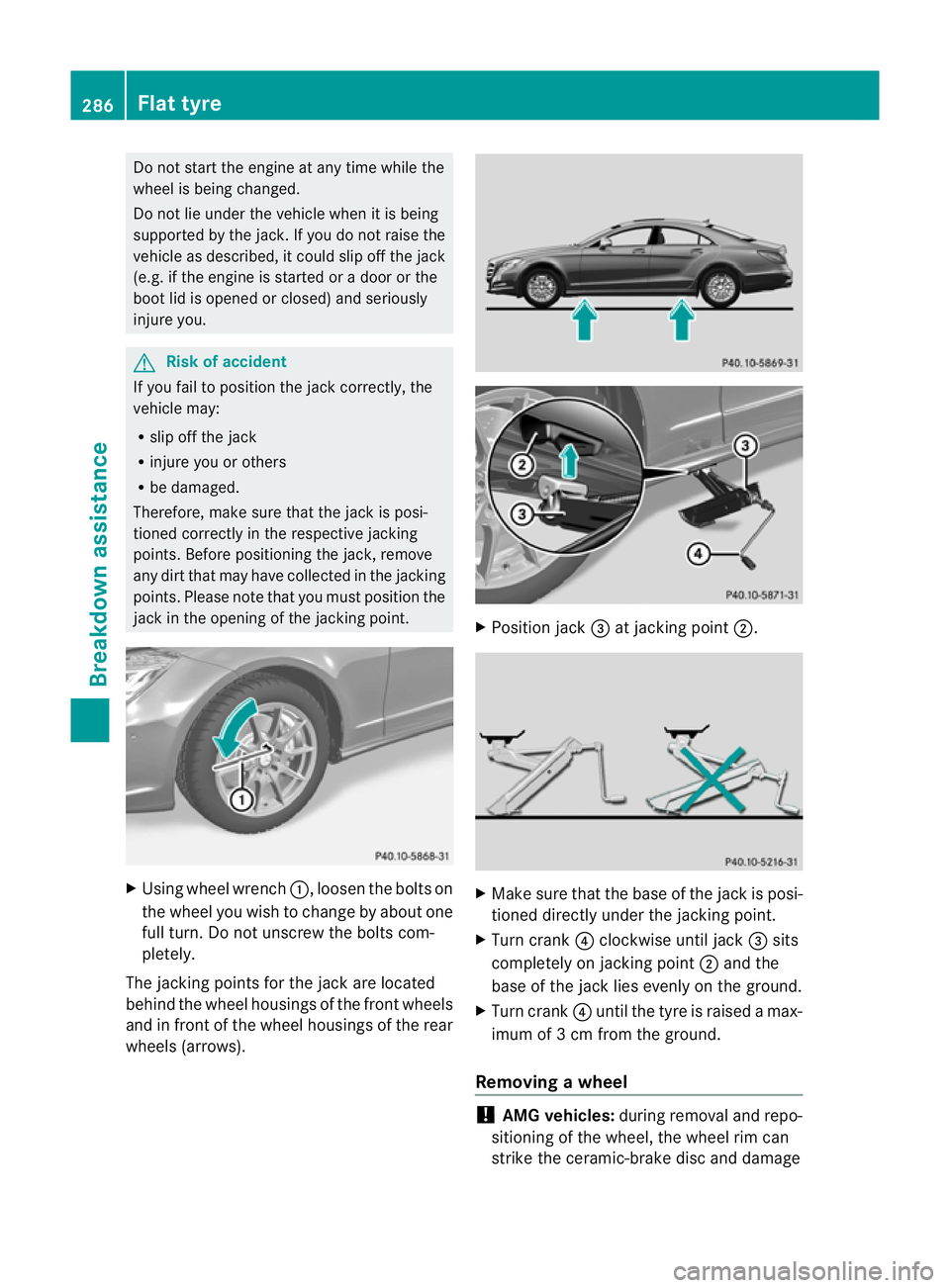
Do not start the engine at any time while the
wheel is being changed.
Do not lie under the vehicle when it is being
supported by the jack. If you do not raise the
vehicle as described, it could slip off the jack
(e.g. if the engine is started or a door or the
boot lid is opened or closed
)and seriously
injure you. G
Ris
kofa ccident
If you fail to position the jack correctly, the
vehicle may:
R slip off the jack
R injure you or others
R be damaged.
Therefore, make sure that the jac kis posi-
tioned correctly in the respective jacking
points. Before positioning the jack, remove
any dirt that may have collected in the jacking
points. Please note that you must position the
jack in the opening of the jacking point. X
Using wheel wrench :, loosen the bolts on
the wheel you wish to change by abouto ne
full turn. Do not unscrew the bolts com-
pletely.
The jacking points for the jack are located
behind the wheel housings of the front wheels
and in front of the wheel housings of the rear
wheels (arrows). X
Positio njack =at jacking point ;. X
Make sure that the base of the jac kis posi-
tioned directly under the jacking point.
X Turn crank ?clockwise until jack =sits
completely on jacking point ;and the
base of the jack lies evenly on the ground.
X Turn crank ?until the tyre is raised a max-
imum of 3 cm from the ground.
Removing awheel !
AMG vehicles: during removal and repo-
sitioning of the wheel, the wheel rim can
strike the ceramic-brake disc and damage 286
Flat tyreBreakdown assistance
Page 309 of 337
rofitted tyre pressure monitors which are
screwed on to the valve may overload it and
cause it to fail .Due to their design, the valve
is kept open continuously, which may lead to
air loss. G
Ris
kofa ccident
Should the tyre pressure drop repeatedly:
R check the tyre for foreign bodies.
R check whether the wheel is losing air or the
valve is leaking.
R make sure that only a valve cap approved
by Mercedes-Benz is fitted on the tyre
valve.
Tyre pressures that are to olow have a nega-
tive effect on vehicle safety, which could lead
you to cause an accident.
If possible, only correc ttyre pressures when
the tyres are cold. The tyres are cold when
the vehicle has been parked fo ratleast three
hours or has been driven less than 1.5 km.
Depending on the ambient temperature, the
speed you are driving at and the load on the
tyres, the tyre temperature and thus the tyre
pressure may change by approximately
10 kPa (0.1 bar, 1.5 psi) per 10 †. Take this
into accoun twhen checking the pressure of
warm tyres and only correct it if it is too low
for the current operating conditions.
Driving with tyre pressure that is too high or
too low can:
R shorten the service life of the tyres
R cause increased tyre damage
R have a negative effect on handling charac-
teristics and thus the driving safety (e.g. by
causing aquaplaning)
i The tyre pressure values given for low
loads are minimum values which offer you
good ride comfort characteristics.
However, you can also use the values given
for higher loads. These are permissible and
will not adversely affect the running of the
vehicle. H
Environmental note
Check the tyre pressure regularly, at least
every 14 days. Tyre pressure loss warning system
Important safety notes While the vehicle is in motion, the tyre pres-
sure loss warning system monitors the set
tyre pressure using the rotational speed of
the wheels. This enables the system to detect
significant pressure loss in a tyre. If the speed
of rotation of a wheel changes as a result of
a loss of pressure, a corresponding warning
message will appearint
he multifunction dis-
play. G
Risk of accident
The tyre pressure loss warning system does
not warn you of an incorrectly set tyre pres-
sure. The table on the inside of the fuel filler
flap will help you decide whether the tyre
pressures should be corrected.
The tyre pressure loss warning system does
not replace the need to regularly check your
vehicle's tyre pressures, since an even loss of
pressure on several tyres at the same time
cannot be detected by the tyre pressure loss
warning system.
The tyre pressure monitor is not able to warn
you of a sudden loss of pressure, e.g. if the
tyre is penetrated by a foreign object.
In the event of a sudden loss of pressure, bring
the vehicle to a halt by braking carefully. Do
not make any sudden steering movements
when doing so.
The function of the tyre pressure loss warning
system is limited or delayed if:
R snow chains are fitted to your vehicle's
tyres.
R road conditions are wintry.
R you are driving on sand or gravel. 306
Tyre pressureWheels and tyres
Page 311 of 337
vehicle to a haltb
y braking carefully. Do not
make any sudden steering movements when
doing so.
Information on tyre pressures is displayed in
the multifunction display. Afte rafew minutes
of driving, the current tyre pressure of each
tyre is show ninthe multifunction display.
i The tyre pressure values indicated by the
on-board computer may differ from those
measured at a filling station with a pressure
gauge. The tyre pressures shown by the on-
board computer refer to those measured at
sea level. At high altitudes, the tyre pres-
sure values indicated by a pressure gauge
are higher than those shown by the on-
board computer. In this case, do not reduce
the tyre pressures.
i The operation of the tyre pressure moni-
tor can be affected by interference from
radio transmitting equipment (e.g. radio
headphones, two-way radios) that may be
being operated in or near the vehicle.
Checking tyre pressure electronically X
Make sure that the key is in posi-
tion 2(Ypage 129) in the ignition lock.
X Use the =or; button on the steer-
ing wheel to select the Service menu.
X Use the 9or: button to select
Tyre pressure .
X Press the abutton.
The current tyre pressure for each wheel
will be displayed in the multifunction dis-
play.
If the vehicle has been parked for longer than
20 minutes, you will see the Tyre pressure
displayed after a few minutes of
driving message.
After a teach-in period, the tyre pressure
monitor automatically recognises new
wheels or new sensors. As long as a clear
allocation of the tyre pressure values to the
individual wheels is not possible, the Tyrepressure monitor active message isshown instead of the tyre pressure display.
The tyre pressures are already being moni-
tored.
i
If a spare wheel/emergency spare wheel
is fitted, for a few minutes the system may
continue to show the tyre pressure of the
wheel that has been removed. If this
occurs, note that the value displayed for
the position where the spare tyre is fitted
is not the same as the spare wheel/emer-
gency spare wheel's current tyre pressure.
Tyre pressure monitor warning mes-
sages If the tyre pressure monitor detects a signifi-
cant pressure loss on one or more tyres, a
warning message is shown in the multifunc-
tion display.
Awarning tone also sounds and
the tyre pressure warning lamp lights up in
the instrument cluster.
Each tyre that is affected by a significant loss
of pressure is highlighted with a colour.
If the Please correct tyre pressure(s) message appears in the multifunction dis-
play:
X
Chec kthe tyre pressure on all four wheels
and correct it if necessary.
i If the wheel positions on the vehicle are
interchanged, the tyre pressures may be
displayed for the wrong positions for a
short time. This is rectified after a few
minutes of driving, and the tyre pressures
are displayed for the correct positions.
Restarting the tyre pressure monitor When you restart the tyre pressure monitor,
all existing warning messages are deleted and
the warning lamps go out. The monitor uses
the currently set tyre pressures as the refer-
ence values for monitoring. In most cases, the
tyre pressure monitor will automatically
detect the new referencev alues after you
have changed the tyre pressure. 308
Tyre pressureWheels and tyres
Page 312 of 337
i
For an overview of the menus, see
(Y page 197).
If you wish to define the new reference values
manually:
X Use the table on the inside of the fuel filler
flap to ensure that the tyre pressure is set
correctly in all four tyres for the current
operating conditions.
Also observe the notes in the section on
tyre pressures (Y page 305).
X Make sure that the key is in position 2in
the ignition lock.
X Use the =or; button on the steer-
ing wheel to select the Service menu.
X Use the 9or: button to select
Tyre pressure .
X Press the abutton.
The current tyre pressure of the individual
wheels is displayed in the multifunction dis-
play or the Tyre pressures will be displayed after a few minutes of
driving message appears.
X Press the :button.
The Use current pressure values as
new reference values message appears
in the multifunction display.
If you wish to confirm the restart:
X Press the abutton.
The Tyre press. monitor restarted message appears in the multifunction dis-
play.
After you have driven for a few minutes, the
system checks whether the current tyre
pressures are within the specified range.
The new tyre pressures are then accepted
as reference values and monitored.
If you wish to cancel the restart:
X Press the %button.
The tyre pressure values stored at the last
restart will continue to be monitored. Changing
awheel Flat tyre
The "Breakdown assistance" section
(Y page 281) contains information and notes
on how to deal with a fla ttyre. It also provides
instructions on changing a wheel or fitting the
spare wheel or emergency spare wheel. Interchanging the wheels
G
Risk of accident
Interchange the front and rear wheels only if
they have the same dimensions :for example
size, offset, etc.
After every wheel interchange/change, have
the tightening torque checked at a qualified
specialist workshop that has the necessary
specialist knowledge and tools to carry out
the work required. Mercedes-Benz recom-
mends that you use a Mercedes-Benz Service
Centre for this purpose. In particular, work
relevant to safety or on safety-related sys-
tems must be carried out at a qualified spe-
cialist workshop.
The wheels could work loose if they are not
tightened to a torque of 130 Nm.
For safety reasons, Mercedes-Benz recom-
mends that you only use wheel bolts of the
correc tsize which have been approved for
Mercedes-Ben zvehicles.
The wear patterns on the fron tand rea rtyres
differ, depending on the operating conditions.
Interchange the wheels before a clear wear
pattern has formed on the tyres. Front tyres
typically wear more on the shoulders and the
rear tyres in the centre.
On vehicles that have th esame size fron tand
rea rwheels, you can interchange the wheels
every 5000 km to 10,000 km depending on
the degree of tyre wear. Do not reverse the
direction of tyre rotation.
Cleant he contact surfaces of the wheel and
the brake disc thoroughly every time a wheel
is interchanged. Check the tyre pressure and, Changing
awheel
309Wheels and tyres Z