2010 KIA SORENTO ESP
[x] Cancel search: ESPPage 311 of 399

75
Maintenance
Engine compartment precautions (Diesel engine)
The piezo injector operates at highvoltage (maximum 200v). Therefore,
the following accidents may occur.
- Direct contact with the injector or
injector wiring may cause electric
shock or damage your muscle or
nerve system.
- The electromagnetic wave from the operating injector may cause the arti-
ficial heart pacemaker to malfunction.
Follow the safety tips provided below, when you are checking the engine
room while the engine is running.
- Do not touch the injector, injector
wirings, and the engine computer
while the engine is running.
- Do not remove the injector connector while the engine is running.
- People using pacemakers must not go near the engine while the engine
is starting or running.
WARNING - Maintenance
work
Performing maintenance work on a vehicle can be dangerous. You
can be seriously injured while
performing some maintenance
procedures. If you lack sufficient
knowledge and experience or the
proper tools and equipment to do
the work, have it done by an
authorized KIA dealer.
Working under the hood with the engine running is dangerous. It
becomes even more dangerous
when you wear jewelry or loose
clothing. These can become
entangled in moving parts and
result in injury. Therefore, if you
must run the engine while work-
ing under the hood, make certain
that you remove all jewelry (espe-
cially rings, bracelets, watches,
and necklaces) and all neckties,
scarves, and similar loose cloth-
ing before getting near theengine or cooling fans.WARNING - Diesel Engine
Never work on the injection system with the engine running or within30 seconds after shutting off the
engine. High-pressure pump, rail,
injectors and high-pressure pipes
are subject to high pressure even
after the engine stopped. The fuel
jet produced by fuel leaks may
cause serious injury, if it touches
the body. People using pacemakers
should not move more than 30cm
closer to the ECU or wiring harness
within the engine room while the
engine is running, since the high
currents in the electronic engine
control system produce consider-
able magnetic fields.
Page 330 of 399

Maintenance
24
7
ENGINE OIL
Checking the engine oil level
1. Be sure the vehicle is on level ground.
2. Start the engine and allow it to reach normal operating temperature. 3. Turn the engine off and wait for a few
minutes (about 5 minutes) for the oil to
return to the oil pan.
4. Pull the dipstick out, wipe it clean, and re-insert it fully.
5. Pull the dipstick out again and check the level. The level should be betweenF and L. If it is near or at L, add enough oil to bring
the level to F.
Do not overfill.
Use a funnel to help prevent oil frombeing spilled on engine components.
Use only the specified engine oil. (Refer to “Recommended lubricants and capaci-ties” in section 8.)
WARNING - Radiator hose
Be very careful not to touch the
radiator hose when checking or
adding the engine oil as it may be
hot enough to burn you.
OXM079005OXM079004
CAUTION
Do not overfill the engine oil. It may damage the engine.
CAUTION - Diesel engine
Overfilling the engine oil may cause
severe dieseling due to churningeffect. It may lead to engine damage
accompanied with abrupt enginespeed increment, combustion noiseand white smoke emission.
Page 351 of 399

745
Maintenance
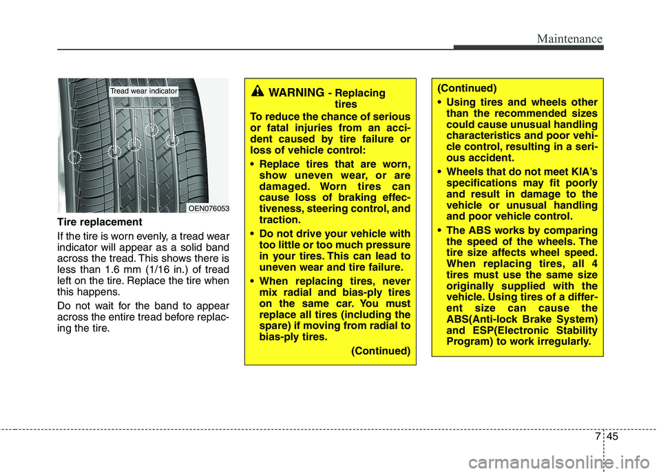
Tire replacement
If the tire is worn evenly, a tread wear indicator will appear as a solid band
across the tread. This shows there isless than 1.6 mm (1/16 in.) of tread
left on the tire. Replace the tire when
this happens.
Do not wait for the band to appear
across the entire tread before replac-
ing the tire.
OEN076053
Tread wear indicatorWARNING - Replacing
tires
To reduce the chance of serious
or fatal injuries from an acci-
dent caused by tire failure or
loss of vehicle control:
Replace tires that are worn, show uneven wear, or are
damaged. Worn tires can
cause loss of braking effec-
tiveness, steering control, andtraction.
Do not drive your vehicle with too little or too much pressure
in your tires. This can lead to
uneven wear and tire failure.
When replacing tires, never mix radial and bias-ply tires
on the same car. You must
replace all tires (including the
spare) if moving from radial to
bias-ply tires.
(Continued)(Continued)
Using tires and wheels otherthan the recommended sizes
could cause unusual handling
characteristics and poor vehi-
cle control, resulting in a seri-ous accident.
Wheels that do not meet KIA’s specifications may fit poorly
and result in damage to the
vehicle or unusual handling
and poor vehicle control.
The ABS works by comparing the speed of the wheels. The
tire size affects wheel speed.
When replacing tires, all 4
tires must use the same size
originally supplied with the
vehicle. Using tires of a differ-
ent size can cause the
ABS(Anti-lock Brake System)
and ESP(Electronic Stability
Program) to work irregularly.
Page 354 of 399

Maintenance
48
7
Tire speed ratings
The chart below lists many of the dif-
ferent speed ratings currently being
used for passenger car tires. The
speed rating is part of the tire size
designation on the sidewall of the
tire. This symbol corresponds to that
tire's designed maximum safe oper-ating speed.3. Checking tire life (TIN : Tire
Identification Number)
Any tires that are over 6 years old,
based on the manufacturing date,(including the spare tire) should be
replaced by new ones. You can find
the manufacturing date on the tire
sidewall (possibly on the inside of the
wheel), displaying the DOT Code.
The DOT Code is a series of num-
bers on a tire consisting of numbers
and English letters. The manufactur-
ing date is designated by the last four
digits (characters) of the DOT code.
DOT : XXXX XXXX OOOO
The front part of the DOT means a
plant code number, tire size and
tread pattern and the last four num-
bers indicate week and year manu-
factured.
For example:
DOT XXXX XXXX 1609 represents
that the tire was produced in the 16th
week of 2009.
4. Tire ply composition and material
The number of layers or plies of rub-
ber-coated fabric in the tire. Tire
manufacturers also must indicate the
materials in the tire, which include
steel, nylon, polyester, and others.
The letter "R" means radial ply con-
struction; the letter "D" means diago-
nal or bias ply construction; and theletter "B" means belted-bias ply con-
struction.
S 180 km/h (112 mph)
T 190 km/h (118 mph)
H 210 km/h (130 mph) V 240 km/h (149 mph)
Z Above 240 km/h (149 mph)
Maximum Speed
Speed
Rating
Symbol
WARNING - Tire age
Tires degrade over time, even
when they are not being used.
Regardless of the remaining
tread, we recommend that tires
be replaced after approximately
six (6) years of normal service.
Heat caused by hot climates orfrequent high loading condi-
tions can accelerate the aging
process. Failure to follow this
warning can result in sudden
tire failure, which could lead to
a loss of control and an acci-
dent involving serious injury ordeath.
Page 355 of 399

749
Maintenance
5. Maximum permissible inflationpressure
This number is the greatest amount of air pressure that should be put in
the tire. Do not exceed the maximum
permissible inflation pressure. Refer
to the Tire and Loading Information
label for recommended inflation
pressure.
6. Maximum load rating
This number indicates the maximum
load in kilograms and pounds that
can be carried by the tire. When
replacing the tires on the vehicle,
always use a tire that has the same
load rating as the factory installed
tire.
7. Uniform tire quality grading
Quality grades can be found where
applicable on the tire sidewall
between tread shoulder and maxi-
mum section width.
For example:
TREADWEAR 200
TRACTION AA
TEMPERATURE A
Tread wear
The tread wear grade is a compara-
tive rating based on the wear rate ofthe tire when tested under controlled
conditions on a specified govern-
ment test course. For example, a tire
graded 150 would wear one-and-a-
half times (1½) as well on the gov-
ernment course as a tire graded 100.
The relative performance of tires depends upon the actual conditions
of their use, however, and may
depart significantly from the norm
due to variations in driving habits,
service practices and differences in
road characteristics and climate. These grades are molded on the
side-walls of passenger vehicle tires.
The tires available as standard or
optional equipment on your vehicle
may vary with respect to grade.
Traction - AA, A, B & C
The traction grades, from highest to
lowest, are AA, A, B and C. Those
grades represent the tire’s ability to
stop on wet pavement as measuredunder controlled conditions on spec-
ified government test surfaces of
asphalt and concrete. A tire marked
C may have poor traction perform-
ance.
WARNING
The traction grade assigned to this tire is based on straight-ahead braking traction tests,
and does not include accelera-
tion, cornering, hydroplaning,
or peak traction characteristics.
Page 362 of 399

Maintenance
56
7
Inner fuse panel (Instrument panel)
1 15A REAR SEAT WARMER LH, RH
2 20A DOOR LOCK, TAILGATE
3 10A THEFT ALARM HORN
4 7.5A RHEOSTAT, IMS
5 10A CLUSTER, SMART KEY, RSE MONITOR, TPMS, AUDIO, REAR PARKING ASSIST SYSTEM
BUZZER, ESP SWITCH, DBC SWITCH, DBC RELAY 'S1', AUTO HLLD SENSOR(4),
HLLD ACTUATOR
6 10A SPORT MODE SWITCH, 4WD ECU
7 20A HEAD LAMP WASHER
8 20A REAR AIR CONDITIONING MOTOR
9 7.5A AIR CONDITIONING SYSTEM, CLUSTER IONIZER, HEAD LAMP WASHER RELAY,
PDM UNIT, FUSIBLE LINK BOX(PTC-3 RELAY'S1'), RAIN SENSOR(1),
SUNROOF MOTOR UNIT(3), ECM(10)
10 15A REAR WIPER, WASHER
11 10A OIL LEVEL SENSOR UNIT(4), PDM UNIT(B9), SMART KEY ECU (A14), 4WD ECU(4), TCU(K3),
GEAR SHIFT INDICATOR, POWER WINDOW
No. Symbol Fuse rating Protected component
RR
3
2
RR
1
Page 366 of 399

Maintenance
60
7
No. Symbol Fuse rating Protected component
8 10A A/CON COMPRESSOR
9 15A FUEL PUMP
10 7.5A BACK UP LAMP, REAR PARKING ASSIST SYSTEM, ECM MIRROR, TCU K(53)
11 7.5A DIAGNOSIS(15), FUSIBLE LINK BOX(FLUID FILLER RELAY 'S1'), GLOW RELAY UNIT(4),
WATER TEMPERATURE SENSOR DIESEL(1), ABS UNIT(3), ESP UNIT(31), STOP SWITCH(3)
12 7.5A ECU, AIR FLOW SENSOR(5), SUB START RELAY
No. Symbol Fuse rating Protected component
15A
6 DIESEL 2.4 GASOLINE 3.5 GASOLINE
EGR COOLING VALVE(2)
VGT ACTUATOR HONEY- WELL(1)
VGT ACTUATOR KAMTEC(3)
P REGUL VALVE(2) FUEL METER UNIT(2)
FUSIBLE LINK BOX(PTC-1
RELAY 'S1')
FUEL PUMP RELAY'S1'O2 SENSOR UP BIN T2(3)
O2 SENSOR UP LIN T2(4)
O2 SENSOR DN FR T2(3)
FUEL PUMP RELAY'S1'
O2 SENSOR 4 PCU(A100) O2 SENSOR 1 O2 SENSOR 3 O2 SENSOR 2
FUEL PUMP RELAY'S1'
7 15A TCU(K1) TCU(K2)PCU K T2(6)
PCU A T2(50)
PCU(A52) PCU(A77)SENSOR4
F/PUMP
B/UP
LP
Page 367 of 399

761
Maintenance
13 50ASUNROOF 20A, SEAT WARMER REAR 15A, HEAD LAMP WASHER 20A, PDM 20A,
SMART KEY 10A
14 50A COOLING FAN LOW(1), COOLING FAN HI(2)
15 15A FRONT DEICER
16 40A IGNITION SWITCH(IG2, ST), START SOLENOID
17 30A IGNITION SWITCH(IG1, ACC)
18 15A HORN LH, RH
19 15A DBC RELAY(ICM), STOP SWITCH"L“, ECU DIESEL(K45), SMART ECU A(24:BRAKE SWITCH),
REAR COMINATION LAMP, HIGH MOUNTED STOP LIGHT, ABS UNIT(14), ESP UNIT(34)
20 15A BATTERY SENSOR
21 60A MODULE 15A, DOOR LAMP 10A, ROOM LAMP 10A, SEAT WARMER FRONT 20A,
POWER SEAT 30A
22 40A BLOWER MOTOR
No. Symbol Fuse rating Protected component
B+4
IGN2
IGN1
STOP LP
B+
SENSO
R
B+2