Page 308 of 407

CAUTION!
Failure to follow these procedures could result in
damage to the charging system of the booster vehicle
or the discharged vehicle.
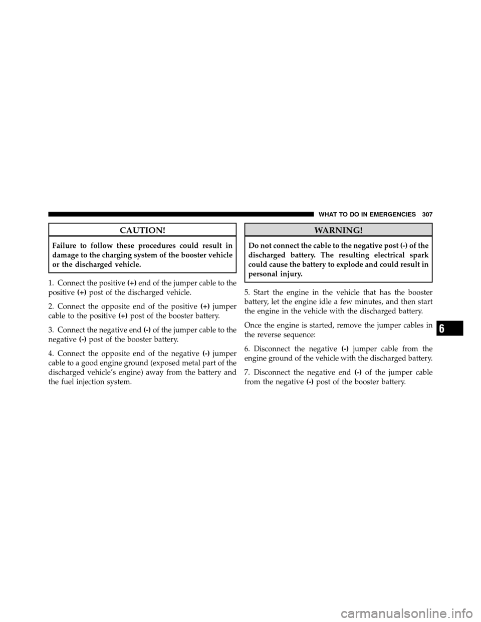
1. Connect the positive (+)end of the jumper cable to the
positive (+)post of the discharged vehicle.
2. Connect the opposite end of the positive (+)jumper
cable to the positive (+)post of the booster battery.
3. Connect the negative end (-)of the jumper cable to the
negative (-)post of the booster battery.
4. Connect the opposite end of the negative (-)jumper
cable to a good engine ground (exposed metal part of the
discharged vehicle’s engine) away from the battery and
the fuel injection system.
WARNING!
Do not connect the cable to the negative post (-) of the
discharged battery. The resulting electrical spark
could cause the battery to explode and could result in
personal injury.
5. Start the engine in the vehicle that has the booster
battery, let the engine idle a few minutes, and then start
the engine in the vehicle with the discharged battery.
Once the engine is started, remove the jumper cables in
the reverse sequence:
6. Disconnect the negative (-)jumper cable from the
engine ground of the vehicle with the discharged battery.
7. Disconnect the negative end (-)of the jumper cable
from the negative (-)post of the booster battery.
6
WHAT TO DO IN EMERGENCIES 307
Page 309 of 407

8. Disconnect the opposite end of the positive(+)jumper
cable from the positive (+)post of the booster battery.
9. Disconnect the positive (+)end of the jumper cable
from the positive (+)post of the discharged vehicle.
10. Reinstall the air intake duct.
If frequent jump-starting is required to start your vehicle
you should have the battery and charging system in-
spected at your authorized dealer.
CAUTION!
Accessories that can be plugged into the vehicle
power outlets draw power from the vehicle’s battery,
even when not in use (i.e., cellular phones, etc.).
Eventually, if plugged in long enough, the vehicle’s
battery will discharge sufficiently to degrade battery
life and/or prevent the engine from starting.
EMERGENCY TOW HOOKS — IF EQUIPPED
If your vehicle is equipped with tow hooks, there will be
one in the rear and two mounted on the front of the
vehicle. The rear hook will be located on the driver’s side
of the vehicle.
NOTE: For off-road recovery, it is recommended to use
both of the front tow hooks to minimize the risk of
damage to the vehicle.
CAUTION!
Tow hooks are for emergency use only, to rescue a
vehicle stranded off road. Do not use tow hooks for
tow truck hookup or highway towing. You could
damage your vehicle.
308 WHAT TO DO IN EMERGENCIES
Page 312 of 407
MAINTAINING YOUR VEHICLE
CONTENTS
�Engine Compartment – 6.1L .............. 313
� Onboard Diagnostic System – OBD II ....... 314
▫ Loose Fuel Filler Cap Message ........... 314
� Emissions Inspection And Maintenance
Programs ............................ 315
� Replacement Parts ..................... 317
� Dealer Service ........................ 317
� Maintenance Procedures ................. 317
▫ Engine Oil ......................... 318 ▫
Engine Oil Filter ..................... 321
▫ Engine Air Cleaner Filter ............... 321
▫ Maintenance-Free Battery .............. 322
▫ Air Conditioner Maintenance ............ 322
▫ Body Lubrication .................... 323
▫ Windshield Wiper Blades ............... 324
▫ Adding Washer Fluid ................. 324
▫ Exhaust System ..................... 325
▫ Cooling System ..................... 328
7
Page 313 of 407

▫Brake System ....................... 334
▫ Automatic Transmission ............... 335
▫ Appearance Care And Protection From
Corrosion .......................... 336
� Fuses .............................. 341
▫ Interior Fuses ....................... 341
▫ Underhood Fuses
(Power Distribution Center) ............. 343
▫ Underhood Fuses
(Integrated Power Module) ............. 346
� Vehicle Storage ....................... 348
� Replacement Bulbs .................... 349
� Bulb Replacement ..................... 349 ▫
High Intensity Discharge Headlamps (HID)
— If Equipped ...................... 349
▫ Halogen Headlamps — If Equipped ....... 350
▫ Front Turn Signal .................... 351
▫ Front Fog Lamp ..................... 352
▫ Rear Tail, Stop, Turn Signal, And Backup
Lamps ............................ 352
▫ Center High-Mounted Stop Lamp
(CHMSL) .......................... 354
� Fluid Capacities ...................... 355
� Fluids, Lubricants, And Genuine Parts ....... 356
▫ Engine ............................ 356
▫ Chassis ........................... 357
312 MAINTAINING YOUR VEHICLE
Page 314 of 407
ENGINE COMPARTMENT – 6.1L
1 — Engine Coolant Reservoir7 — Engine Oil Dipstick
2 — Power Distribution Center 8 — Power Steering Fluid Reservoir
3 — Brake Fluid Reservoir 9 — Engine Oil Fill
4 — Integrated Power Module 10 — Coolant Pressure Cap
5 — Battery 11 — Air Cleaner Filter
6 — Washer Fluid Reservoir7
MAINTAINING YOUR VEHICLE 313
Page 315 of 407

ONBOARD DIAGNOSTIC SYSTEM – OBD II
Your vehicle is equipped with a sophisticated onboard
diagnostic system called OBD II. This system monitors
the performance of the emissions, engine, and automatic
transmission control systems. When these systems are
operating properly, your vehicle will provide excellent
performance and fuel economy, as well as engine emis-
sions well within current government regulations.
If any of these systems require service, the OBD II system
will turn on the “Malfunction Indicator Light” (MIL). It
will also store diagnostic codes and other information to
assist your service technician in making repairs. Al-
though your vehicle will usually be drivable and not
need towing, see your authorized dealer for service as
soon as possible.CAUTION!
•Prolonged driving with the MIL on could cause
further damage to the emission control system. It
could also affect fuel economy and drivability. The
vehicle must be serviced before any emissions
tests can be performed.
•If the MIL is flashing while the engine is running,
severe catalytic converter damage and power loss
will soon occur. Immediate service is required.
Loose Fuel Filler Cap Message
After fuel is added, the vehicle diagnostic system can
determine if the fuel filler cap is loose, improperly
installed, or damaged. A “CHECK GASCAP” message
will be displayed in the EVIC. Refer to “Electronic Vehicle
Information Center (EVIC)” in “Understanding Your
Instrument Panel” for further information. Tighten the
314 MAINTAINING YOUR VEHICLE
Page 316 of 407

gas cap until a�clicking�sound is heard. This is an
indication that the gas cap is properly tightened.
The message will remain displayed until the vehicle
diagnostic system can retest the fuel system. The test will
perform the next time the vehicle is started, if the vehicle
was keyed off above 40°F (4°C) outside temperature and
the following vehicle start is above 40°F (4°C) outside
temperature. It may be possible to have a message that
will not clear due to the test being disabled due to low
outside temperatures. If the test is performed and the
problem is gone, the message will disappear.
If the problem persists, the message will appear the next
time the vehicle is started. This might indicate a damaged
cap. If the problem is detected twice in a row, the system
will turn on the MIL. Resolving the problem will turn the
MIL off. See your authorized dealer for service.EMISSIONS INSPECTION AND MAINTENANCE
PROGRAMS
In some localities, it may be a legal requirement to pass
an inspection of your vehicle’s emissions control system.
Failure to pass could prevent vehicle registration.
For states that require an Inspection and Mainte-
nance (I/M), this check verifies the “Malfunction
Indicator Light (MIL)” is functioning and is not
on when the engine is running, and that the OBD II
system is ready for testing.
Normally, the OBD II system will be ready. The OBD II
system may notbe ready if your vehicle was recently
serviced, recently had a dead battery or a battery replace-
ment. If the OBD II system should be determined not
ready for the I/M test, your vehicle may fail the test.
7
MAINTAINING YOUR VEHICLE 315
Page 317 of 407

Your vehicle has a simple ignition key-actuated test,
which you can use prior to going to the test station. To
check if your vehicle’s OBD II system is ready, you must
do the following:
1. Turn the ignition switch to the ON position, but do not
crank or start the engine.
2. If you crank or start the engine, you will have to start
this test over.
3. As soon as you turn the ignition switch to the ON
position, you will see the MIL symbol come on as part of
a normal bulb check.
4. Approximately 15 seconds later, one of two things will
happen:a. The MIL will flash for about 10 seconds and then
return to being fully illuminated until you turn OFF the ignition or start the engine. This means that your
vehicle’s OBD II system is
not readyand you should
not proceed to the I/M station.
b. The MIL will not flash at all and will remain fully
illuminated until you turn OFF the ignition or start the
engine. This means that your vehicle’s OBD II system
is ready and you can proceed to the I/M station.
If your OBD II system is not ready,you should see your
authorized dealer or repair facility. If your vehicle was
recently serviced or had a battery failure or replacement,
you may need to do nothing more than drive your
vehicle as you normally would in order for your OBD II
system to update. A recheck with the above test routine
may then indicate that the system is now ready.
Regardless of whether your vehicle’s OBD II system is
ready or not, if the MIL is illuminated during normal
vehicle operation you should have your vehicle serviced
316 MAINTAINING YOUR VEHICLE