2010 JAGUAR XFR Right Front Height Sensor
[x] Cancel search: Right Front Height SensorPage 110 of 3039

DTC Description Possible Causes Action C1A04-12
Right Front
Height Sensor -
Circuit short to
power
Height sensor circuit
shorted to another
cable
Height sensor internal
fault
Refer to the electrical circuit diagrams and check Front Right
Height Sensor circuit for short to power, If circuit correct
suspect Sensor internal fault, replace as required C1A04-14
Right Front
Height Sensor -
Circuit short to
ground or open
Wiring to sensor
(signal) open circuit
Wiring to height
sensor partial short to
ground
Wiring to height
sensor short to other
cable
Height sensor internal
electrical fault
Disconnect electrical connector to height sensor and inspect
connector pins & terminals for evidence of corrosion or water
ingress. If no corrosion found, disconnect harness at Control
Module. A: Check for short circuits between any of the 3
terminals and vehicle ground. B: Check for electrical continuity
between the two connectors for each of the 3 terminals.
Reconnect electrical connector at Control Module only. C:
Check voltages at terminals within height sensor connector
(sensor not connected), with respect to vehicle body. •
Voltage to sensor ground connection should be ~0v • Voltage
to sensor signal connection should be ~0v • Voltage to sensor
supply connection should be ~5v All voltages should be within
± 0.15v C1A04-21
Right Front
Height Sensor -
Signal amplitude
< minimum
Height sensor linkage
not connected
Height sensor or
bracket loose
Height sensor bracket
bent
Incorrect height
calibration
Height sensor linkage
toggled
Height sensor water
ingress
Wiring to height
sensor partial short to
ground
Wiring to height
sensor short to other
cable
Height sensor
electrical fault
Height sensor linkage
bent
Incorrect height
sensor fitted
Inspect for damage or loose fixings. NOTE If any height
sensor fixings were slackened or found to be loose or if a
height sensor was changed, the vehicle ride height MUST be
re-calibrated. Confirm that the correct height sensor part
number is fitted, as specified in the service parts database.
To check height sensor: Disconnect electrical connector to
height sensor and inspect connecter pins & terminals for
evidence of corrosion or water ingress. If no corrosion found,
disconnect harness at Control Module. A: Check for short
circuits between any of the 3 terminals and vehicle ground. B:
Check for electrical continuity between the two connectors for
each of the 3 terminals. Reconnect electrical connector at
Control Module only. C: Check voltages at terminals within
height sensor connector (sensor not connected), with respect
to vehicle body. • Voltage to sensor ground connection should
be ~0v • Voltage to sensor signal connection should be ~0v •
Voltage to sensor supply connection should be ~5v All
voltages should be within ± 0.15v. To check sensor operation
on the vehicle: Check for water ingress around the height
sensors, electrical connectors or shaft end. Check for
excessive movement in the shaft in all directions. Raise
vehicle (ideally on wheels-free ramp) until suspension on
corner under investigation is at rebound to gain access to
height sensor. Access may be improved by removing road
wheel. Carefully disconnect the height sensor link from the
upper suspension arm. Monitor the height sensor signal
voltage output for the height sensor under investigation.
Position the sensor arm so it is in the mid position and
confirm that the voltage is around 2.5 volts. Move the sensor
arm over the range ±40° around the mid position and confirm
that the voltage changes smoothly between around 0.2 volts
and 4.8 volts. If voltages are incorrect or do not change
smoothly then replace sensor. NOTE: For angles of movement
beyond ±40°, the sensor signal will clamp to a voltage of
~0.15v or ~4.85v, depending on position of sensor lever. This
is normal. When investigation is complete, refit height sensor
link to upper arm. If any fixings to the height sensor body or
mounting bracket were slackened or found to be loose or if a
height sensor was changed, the vehicle ride height MUST be
re-calibrated. Refer to the relevant section of the workshop
manual for the calibration procedure C1A04-22
Right Front
Height Sensor -
Signal amplitude
> maximum
Height sensor linkage
not connected
Height sensor or
bracket loose
Height sensor bracket
bent
Incorrect height
calibration
Height sensor linkage
toggled
Height sensor water
ingress
Wiring to height
Inspect for damage or loose fixings. NOTE If any height
sensor fixings were slackened or found to be loose or if a
height sensor was changed, the vehicle ride height MUST be
re-calibrated. Confirm that the correct height sensor part
number is fitted, as specified in the service parts database.
To check height sensor: Disconnect electrical connector to
height sensor and inspect connecter pins & terminals for
evidence of corrosion or water ingress. If no corrosion found,
disconnect harness at Control Module. A: Check for short
circuits between any of the 3 terminals and vehicle ground. B:
Check for electrical continuity between the two connectors for
each of the 3 terminals. Reconnect electrical connector at
Control Module only. C: Check voltages at terminals within www.JagDocs.com
Page 111 of 3039

DTC Description Possible Causes Action sensor partial short to
ground
Wiring to height
sensor short to other
cable
Height sensor
electrical fault
Height sensor linkage
bent
Incorrect height
sensor fitted height sensor connector (sensor not connected), with respect
to vehicle body. • Voltage to sensor ground connection should
be ~0v • Voltage to sensor signal connection should be ~0v •
Voltage to sensor supply connection should be ~5v All
voltages should be within ± 0.15v. To check sensor operation
on the vehicle: Check for water ingress around the height
sensors, electrical connectors or shaft end. Check for
excessive movement in the shaft in all directions. Raise
vehicle (ideally on wheels-free ramp) until suspension on
corner under investigation is at rebound to gain access to
height sensor. Access may be improved by removing road
wheel. Carefully disconnect the height sensor link from the
upper suspension arm. Monitor the height sensor signal
voltage output for the height sensor under investigation.
Position the sensor arm so it is in the mid position and
confirm that the voltage is around 2.5 volts. Move the sensor
arm over the range ±40° around the mid position and confirm
that the voltage changes smoothly between around 0.2 volts
and 4.8 volts. If voltages are incorrect or do not change
smoothly then replace sensor. NOTE: For angles of movement
beyond ±40°, the sensor signal will clamp to a voltage of
~0.15v or ~4.85v, depending on position of sensor lever. This
is normal. When investigation is complete, refit height sensor
link to upper arm. If any fixings to the height sensor body or
mounting bracket were slackened or found to be loose or if a
height sensor was changed, the vehicle ride height MUST be
re-calibrated. Refer to the relevant section of the workshop
manual for the calibration procedure C1A04-76
Right Front
Height Sensor -
Wrong mounting position
Incorrect height
calibration
Refer to the workshop manual and perform the height sensor
calibration procedure. Clear the DTC and retest the system C1A04-78
Right Front
Height Sensor -
Alignment or
adjustment
incorrect
Incorrect height
calibration
Refer to the workshop manual and perform the height sensor
calibration procedure. Clear the DTC and retest the system C1A05-12
Left Rear Height
Sensor - Circuit
short to power
Height sensor circuit
shorted to another
cable
Height sensor internal
fault
Refer to the electrical circuit diagrams and check Rear Left
Height Sensor circuit for short to power, If circuit correct
suspect Sensor internal fault, replace as required C1A05-14
Left Rear Height
Sensor - Circuit
short to ground
or open
Wiring to sensor
(signal) open circuit
Wiring to height
sensor partial short to
ground
Wiring to height
sensor short to other
cable
Height sensor internal
electrical fault
Disconnect electrical connector to height sensor and inspect
connector pins & terminals for evidence of corrosion or water
ingress. If no corrosion found, disconnect harness at Control
Module. A: Check for short circuits between any of the 3
terminals and vehicle ground. B: Check for electrical continuity
between the two connectors for each of the 3 terminals.
Reconnect electrical connector at Control Module only. C:
Check voltages at terminals within height sensor connector
(sensor not connected), with respect to vehicle body. •
Voltage to sensor ground connection should be ~0v • Voltage
to sensor signal connection should be ~0v • Voltage to sensor
supply connection should be ~5v All voltages should be within
± 0.15v C1A05-21
Left Rear Height
Sensor - Signal
amplitude <
minimum
Height sensor linkage
not connected
Height sensor or
bracket loose
Height sensor bracket
bent
Incorrect height
calibration
Height sensor linkage
toggled
Height sensor water
ingress
Wiring to height
sensor partial short to
ground
Wiring to height
sensor short to other
Inspect for damage or loose fixings. NOTE If any height
sensor fixings were slackened or found to be loose or if a
height sensor was changed, the vehicle ride height MUST be
re-calibrated. Confirm that the correct height sensor part
number is fitted, as specified in the service parts database.
To check height sensor: Disconnect electrical connector to
height sensor and inspect connecter pins & terminals for
evidence of corrosion or water ingress. If no corrosion found,
disconnect harness at Control Module. A: Check for short
circuits between any of the 3 terminals and vehicle ground. B:
Check for electrical continuity between the two connectors for
each of the 3 terminals. Reconnect electrical connector at
Control Module only. C: Check voltages at terminals within
height sensor connector (sensor not connected), with respect
to vehicle body. • Voltage to sensor ground connection should
be ~0v • Voltage to sensor signal connection should be ~0v •
Voltage to sensor supply connection should be ~5v All
Page 114 of 3039
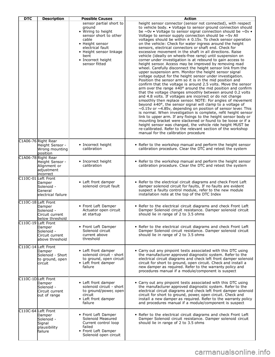
DTC Description Possible Causes Action sensor partial short to
ground
Wiring to height
sensor short to other
cable
Height sensor
electrical fault
Height sensor linkage
bent
Incorrect height
sensor fitted height sensor connector (sensor not connected), with respect
to vehicle body. • Voltage to sensor ground connection should
be ~0v • Voltage to sensor signal connection should be ~0v •
Voltage to sensor supply connection should be ~5v All
voltages should be within ± 0.15v. To check sensor operation
on the vehicle: Check for water ingress around the height
sensors, electrical connectors or shaft end. Check for
excessive movement in the shaft in all directions. Raise
vehicle (ideally on wheels-free ramp) until suspension on
corner under investigation is at rebound to gain access to
height sensor. Access may be improved by removing road
wheel. Carefully disconnect the height sensor link from the
upper suspension arm. Monitor the height sensor signal
voltage output for the height sensor under investigation.
Position the sensor arm so it is in the mid position and
confirm that the voltage is around 2.5 volts. Move the sensor
arm over the range ±40° around the mid position and confirm
that the voltage changes smoothly between around 0.2 volts
and 4.8 volts. If voltages are incorrect or do not change
smoothly then replace sensor. NOTE: For angles of movement
beyond ±40°, the sensor signal will clamp to a voltage of
~0.15v or ~4.85v, depending on position of sensor lever. This
is normal. When investigation is complete, refit height sensor
link to upper arm. If any fixings to the height sensor body or
mounting bracket were slackened or found to be loose or if a
height sensor was changed, the vehicle ride height MUST be
re-calibrated. Refer to the relevant section of the workshop
manual for the calibration procedure C1A06-76
Right Rear
Height Sensor -
Wrong mounting position
Incorrect height
calibration
Refer to the workshop manual and perform the height sensor
calibration procedure. Clear the DTC and retest the system C1A06-78
Right Rear
Height Sensor -
Alignment or
adjustment
incorrect
Incorrect height
calibration
Refer to the workshop manual and perform the height sensor
calibration procedure. Clear the DTC and retest the system C110C-01
Left Front
Damper
Solenoid -
General
electrical failure
Left front damper
solenoid circuit fault
Refer to the electrical circuit diagrams and check Front Left
damper solenoid circuit for faults, If no faults are evident
suspect a faulty control module, refer to the new module
installation note at the top of the DTC Index C110C-18
Left Front
Damper
Solenoid -
Circuit current
below threshold
Front Left Damper
Actuator open circuit
at startup
Refer to the electrical circuit diagrams and check Front Left
Damper Solenoid circuit resistance. Damper solenoid circuit
should lie in range of 2 to 3.5 ohms C110C-19
Left Front
Damper
Solenoid -
Circuit current
above threshold
Front Left Damper
Solenoid circuit
current above
threshold
Refer to the electrical circuit diagrams and check Front Left
Damper Solenoid circuit resistance. Damper solenoid circuit
should lie in range of 2 to 3.5 ohms C110C-14
Left Front
Damper
Solenoid - Short
to ground, open
circuit
Left front damper
solenoid circuit - short
to ground, open circuit
Left front damper
failure
Carry out any pinpoint tests associated with this DTC using
the manufacturer approved diagnostic system. Refer to the
electrical circuit diagrams and check left front damper solenoid
circuit for short to ground, open circuit. Check and install a
new damper as required. Refer to the warranty policy and
procedures manual if a module/component is suspect C110C-1D
Left Front
Damper
Solenoid -
Circuit current
out of range
Left front damper
solenoid circuit - short
to ground/power, open
circuit
Left front damper
failure
Carry out any pinpoint tests associated with this DTC using
the manufacturer approved diagnostic system. Refer to the
electrical circuit diagrams and check left front damper solenoid
circuit for short to ground, power, open circuit. Check and
install a new damper as required. Refer to the warranty policy
and procedures manual if a module/component is suspect C110C-64
Left Front
Damper
Solenoid -
Signal
plausibility
failure
Front Left Damper
Solenoid Measured
Current control loop
failed
Front Left Damper
Solenoid open circuit
Refer to the electrical circuit diagrams and check Front Left
Damper Solenoid circuit resistance. Damper solenoid circuit
should lie in range of 2 to 3.5 ohms
Page 116 of 3039

DTC Description Possible Causes Action plausibility
failure failed
Rear Left Damper
Solenoid open circuit C110F-01
Right Rear
Damper
Solenoid -
General
Electrical Failure
Right Rear damper
solenoid circuit fault
Refer to the electrical circuit diagrams and check Rear Right
damper solenoid circuit for faults, If no faults are evident
suspect a faulty control module, refer to the new module
installation note at the top of the DTC Index C110F-18
Right Rear
Damper
Solenoid -
Circuit current
below threshold
Rear Right Damper
Actuator open circuit
at startup
Refer to the electrical circuit diagrams and check Rear Right
Damper Solenoid circuit resistance. Damper solenoid circuit
should lie in range of 2 to 3.5 ohms C110F-19
Right Rear
Damper
Solenoid -
Circuit current
above threshold
Rear Right Damper
Solenoid circuit
current above
threshold
Refer to the electrical circuit diagrams and check Rear Right
Damper Solenoid circuit resistance. Damper solenoid circuit
should lie in range of 2 to 3.5 ohms C110F-14
Right Rear
Damper
Solenoid - Short
to ground, open
circuit
Right Rear damper
solenoid circuit - short
to ground, open circuit
Right Rear damper
failure
Carry out any pinpoint tests associated with this DTC using
the manufacturer approved diagnostic system. Refer to the
electrical circuit diagrams and check Right Rear damper
solenoid circuit for short to ground, open circuit. Check and
install a new damper as required. Refer to the warranty policy
and procedures manual if a module/component is suspect C110F-1D
Right Rear
Damper
Solenoid -
Circuit current
out of range
Right Rear damper
solenoid circuit - short
to ground/power, open
circuit
Right Rear damper
failure
Carry out any pinpoint tests associated with this DTC using
the manufacturer approved diagnostic system. Refer to the
electrical circuit diagrams and check Right Rear damper
solenoid circuit for short to ground, power, open circuit. Check
and install a new damper as required. Refer to the warranty
policy and procedures manual if a module/component is
suspect C110F-64
Right Rear
Damper
Solenoid -
Signal
plausibility
failure
Rear Right Damper
Solenoid Measured
Current control loop
failed
Rear Right Damper
Solenoid open circuit
Refer to the electrical circuit diagrams and check Rear Right
Damper Solenoid circuit resistance. Damper solenoid circuit
should lie in range of 2 to 3.5 ohms C1B14-1C
Sensor Supply
Voltage A - Out
of range
Left Front Height
Sensor or Right Front
Height Sensor or Left
Rear Height Sensor or
Right Rear Height
Sensor supply partial
short to other circuit
or ground
Left Front Height
Sensor or Right Front
Height Sensor or Left
Rear Height Sensor or
Right Rear Height
Sensor internal failure
Internal control
module failure
Refer to the electrical circuit diagrams and check sensor
supply for circuit fault. Check all height sensors. Check
module sensor supply output voltage measured voltage
should be between 4.995 volts and 4.85 volts C1B15-1C
Sensor Supply
Voltage B - Out
of range
Left Front Vertical
Acceleration Sensor or
Right Front Vertical
Acceleration Sensor or
Left Rear Vertical
Acceleration Sensor or
Right Rear Vertical
Acceleration Sensor
supply partial short to
other circuit or
ground. Left Front
Vertical Acceleration
Sensor or Right Front
Vertical Acceleration
Refer to the electrical circuit diagrams and check sensor
supply for circuit fault. Check all Vertical Acceleration Sensors.
Check control module sensor supply output voltage Measured
voltage should be between 4.995 volts and 4.85 volts
Page 184 of 3039

DTC Description Possible Causes Action B10AE-64
Headlamp Leveling
Motor - Signal
plausibility failure
Signal plausibility
failure voltage out of
range
Refer to the electrical circuit diagrams and check the
Headlamp Leveling Motor circuits for failure. Disconnect one
headlamp connector, clear DTC and re-test. If DTC cleared,
suspect Headlamp Leveling Module or circuits to the
disconnected side. If DTC remains, reconnect first
headlamp and disconnect second, clear DTC and re-test. If
DTC cleared, suspect Headlamp Leveling Module or circuits
to the disconnected side. If DTC remains, suspect common
circuits of the failure. Refer to the electrical circuit diagrams
and check as required B1A59-11
Sensor 5 Volt
Supply - Circuit
short to ground
Headlamp Leveling
Sensor 5 volt supply
circuit short to ground
Refer to electrical circuit diagrams and check Headlamp
Leveling Sensor 5 volt supply circuit for short to ground B1A59-12
Sensor 5 Volt
Supply - General
electrical failure
Headlamp Leveling
Sensor 5 volt supply
circuit short to power
Refer to electrical circuit diagrams and check Headlamp
Leveling Sensor 5 volt supply circuit for short to power C1A04-11
Right Front Height
Sensor - Circuit
short to ground
Right front Height
Sensor circuit short to
ground
Refer to the electrical circuit diagrams, and check Right
Front Height Sensor circuit for short to ground C1A04-15
Right Front Height
Sensor - Circuit
short to battery or
open
Right front Height
Sensor circuit short to
power or open circuit
Check Right Front Height Sensor connector for security.
Refer to the electrical circuit diagrams, and check Right
Front Height Sensor circuit for short to power or open circuit C1A04-64
Right Front Height
Sensor - Signal
plausibility failure
Sensor (PWM) Signal
out of range
NOTE: This DTC may be logged if the vehicles wheels have
been raised from the floor
Check the location, security and mechanical operation of
the Height Sensor. Refer to the electrical circuit diagrams,
and check Right Front Height Sensor signal circuit for fault C1A06-11
Right Rear Height
Sensor - Circuit
short to ground
Right rear Height
Sensor circuit short to
ground
Refer to the electrical circuit diagrams, and check Right
Rear Height Sensor circuit for short to ground C1A06-15
Right Rear Height
Sensor - Circuit
short to battery or
open
Right rear Height
Sensor circuit short to
power or open circuit
Check Right Rear Height Sensor connector for security. Refer
to the electrical circuit diagrams, and check Right Rear
Height Sensor circuit for short to power or open circuit C1A06-64
Right Rear Height
Sensor - Signal
plausibility failure
Sensor (PWM) Signal
out of range
NOTE: This DTC may be logged if the vehicles wheels have
been raised from the floor
Check the location, security and mechanical operation of
the Height Sensor. Refer to the electrical circuit diagrams,
and check Right Rear Height Sensor signal circuit for fault U0001-88
High Speed CAN
Communication Bus
- Bus off
CAN Bus Off
CAN Bus Circuit fault
Check other modules for stored DTCs. Carry out the CAN
Network Integrity test using the manufacturer approved
diagnostic system U0101-00
Lost Communication
with TCM - No sub
type information
Lost communication
with the Transmission
Control Module
CAN network fault
Check the Transmission Control Module for stored DTCs.
Using the manufacturer approved diagnostic system,
complete the CAN Network Integrity test. Refer to the
electrical circuit diagrams and check the CAN network
between the Headlamp Leveling Module and the
Transmission Control Module U0121-00
Lost Communication
With Anti-Lock
Brake System (ABS)
Control Module - No
sub type
information
Lost communication
with the Anti-lock
Brake System Module
CAN network fault
Check the Anti-lock Brake System Module for stored DTCs.
Using the manufacturer approved diagnostic system,
complete the CAN Network Integrity test. Refer to the
electrical circuit diagrams and check the CAN network
between the Headlamp Leveling Module and the Anti-lock
Brake System Module
Page 479 of 3039
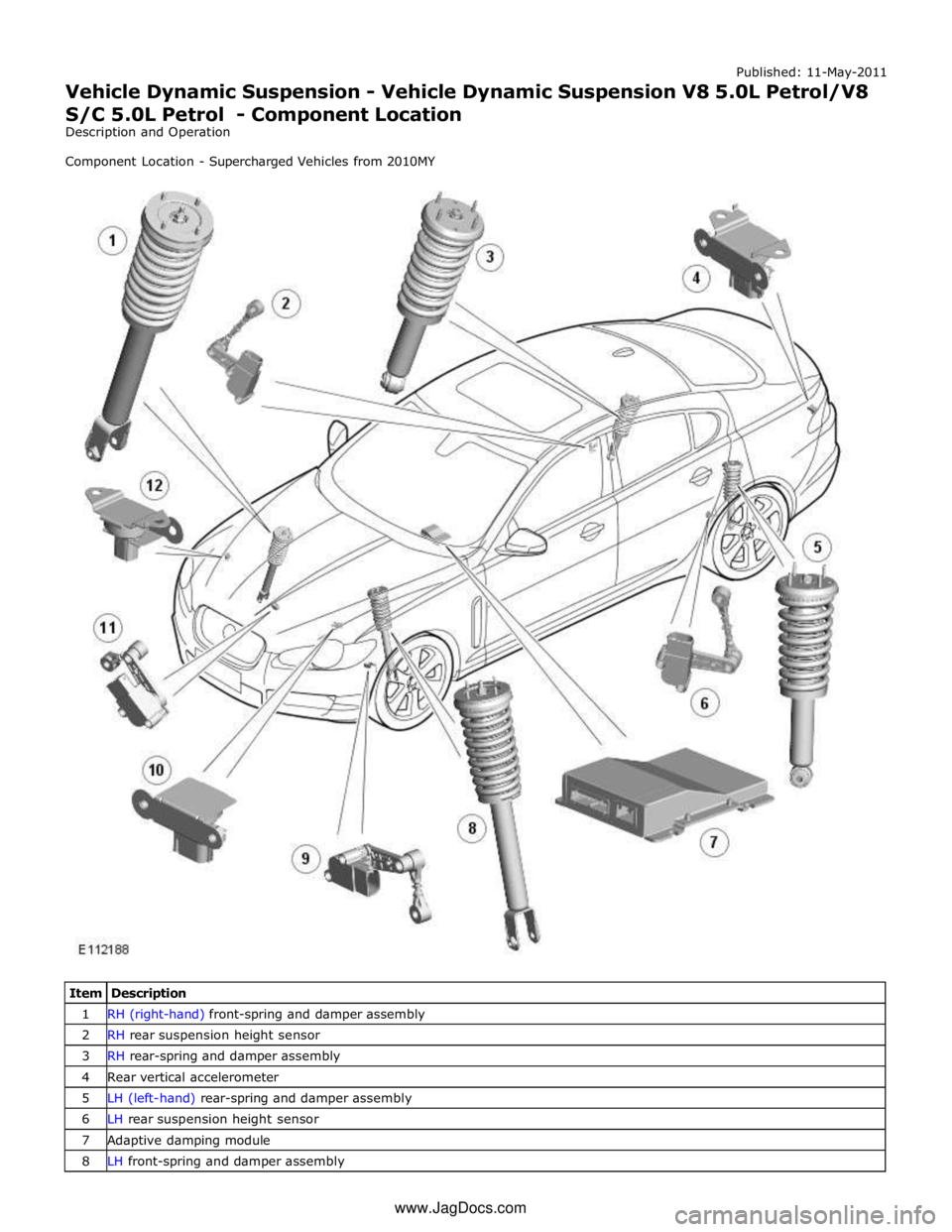
1 RH (right-hand) front-spring and damper assembly 2 RH rear suspension height sensor 3 RH rear-spring and damper assembly 4 Rear vertical accelerometer 5 LH (left-hand) rear-spring and damper assembly 6 LH rear suspension height sensor 7 Adaptive damping module 8 LH front-spring and damper assembly www.JagDocs.com
Page 481 of 3039

Published: 11-May-2011
Vehicle Dynamic Suspension - Vehicle Dynamic Suspension V8 5.0L Petrol/V8 S/C 5.0L Petrol - Overview
Description and Operation
OVERVIEW
Adaptive Dynamics - Supercharged Vehicles from 2010MY
The adaptive dynamics system, is an electronically controlled suspension system which constantly adjusts the damping
characteristics of the suspension dampers in reaction to the existing driving conditions. The adaptive dynamics system is
available on specified models.
The system is controlled by an Adaptive Damping Module (ADM), located beneath the right-hand front seat. The module
receives signals from three dedicated vertical accelerometers; two at the front of the vehicle and one at the rear, which,
together with four suspension height sensors, determine the state of the body and wheel motions. In addition to these inputs,
further signals from other vehicle electronic system components to determine vehicle state and driver inputs are monitored by
the adaptive damping module. These combined signals are used by the adaptive damping module to continuously adjust the
damping characteristics of each of the suspension dampers in reaction to the current driving conditions to give the optimum
body control and vehicle ride.
Page 483 of 3039

7 Rear accelerometer 8 Instrument cluster 9 JaguarDrive selector module 10 ABS (anti-lock brake system) module 11 TCM (transmission control module) 12 ECM (engine control module) 13 RH (right-hand) rear damper 14 RH front damper 15 LH (left-hand) front damper 16 LH rear damper 17 LH rear suspension height sensor 18 RH rear suspension height sensor 19 LH front suspension height sensor 20 RH front accelerometer 21 RH front suspension height sensor 22 Adaptive damping module 23 LH front accelerometer
PRINCIPLES OF OPERATION System Operation
The adaptive damping module uses a combination of information from other system modules and data from the accelerometers
and suspension height sensors to measure the vehicle and suspension states and driver inputs. Using this information, the
adaptive damping module applies algorithms to control the dampers for the current driving conditions.
The adaptive damping module receives signals on the high speed CAN bus from the following system components: Brake Pressure - ABS module. Brake Pressure Quality Factor - ABS module. Car Configuration Parameters - AJB. Center Differential Range Actual - ECM. Engine Speed - ECM. Engine Speed Quality Factor - ECM. Engine Torque Flywheel Actual - ECM. Engine Torque Flywheel Actual Quality Factor - ECM. Gear Position Target - TCM. Lateral Acceleration - ABS module. Power Mode (Ignition Signal) - CJB. Power Mode Quality Factor - CJB. Roll Stability Control Mode - ABS module. Steering Wheel Angle - ABS module. Steering Wheel Angle Speed - ABS module. Steering Wheel Angle Status - ABS module. Terrain Mode Requested - JaguarDrive selector.
Torque Converter Slip - TCM. Vehicle Information Parameters HS - AJB Vehicle Speed - ABS module. Vehicle Speed Quality Factor - ABS module. Front Left Wheel Speed - ABS module. Front Left Wheel Speed Quality Factor - ABS module. Front Right Wheel Speed - ABS module. Front Right Wheel Speed Quality Factor - ABS module. Rear Left Wheel Speed - ABS module. Rear Left Wheel Speed Quality Factor - ABS module. Rear Right Wheel Speed Quality Factor - ABS module. Rear Right Wheel Speed - ABS module. The adaptive damping module also outputs information on the high speed CAN bus for use by other systems as follows: Fault Message - instrument cluster.
Terrain Mode Change Status - JaguarDrive selector.
Terrain Mode - JaguarDrive selector.
The adaptive damping module monitors the input signals and operates the damper solenoids. The input signals are used in
control modes and a force required for each damper for that mode is calculated. An arbitration mode monitors the force
requirements from each mode and apportions a force to a damper. The force is converted to the appropriate current and sent to
the damper.
The control modes are as follows: