Page 1298 of 3039

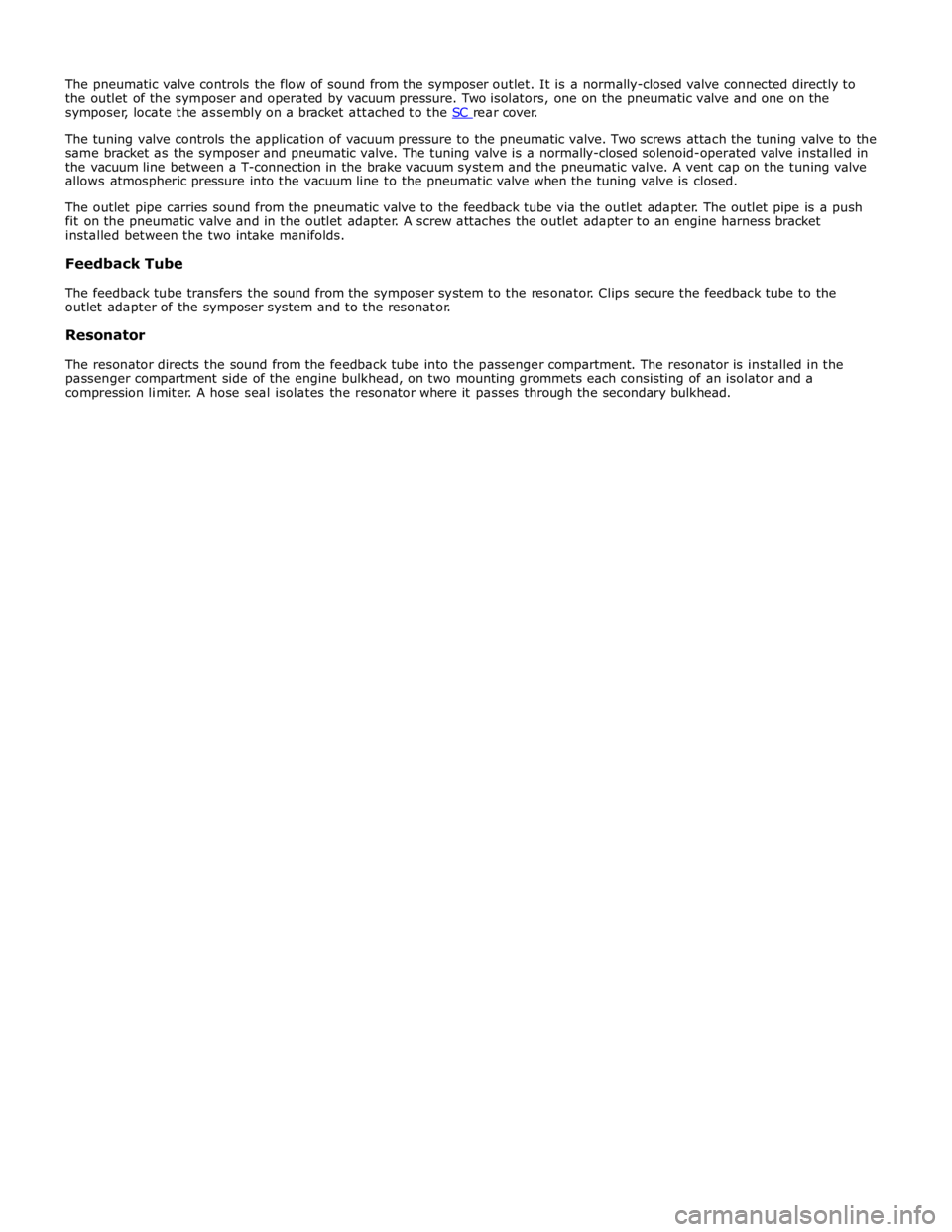
The tuning valve controls the application of vacuum pressure to the pneumatic valve. Two screws attach the tuning valve to the
same bracket as the symposer and pneumatic valve. The tuning valve is a normally-closed solenoid-operated valve installed in
the vacuum line between a T-connection in the brake vacuum system and the pneumatic valve. A vent cap on the tuning valve
allows atmospheric pressure into the vacuum line to the pneumatic valve when the tuning valve is closed.
The outlet pipe carries sound from the pneumatic valve to the feedback tube via the outlet adapter. The outlet pipe is a push
fit on the pneumatic valve and in the outlet adapter. A screw attaches the outlet adapter to an engine harness bracket
installed between the two intake manifolds.
Feedback Tube
The feedback tube transfers the sound from the symposer system to the resonator. Clips secure the feedback tube to the
outlet adapter of the symposer system and to the resonator.
Resonator
The resonator directs the sound from the feedback tube into the passenger compartment. The resonator is installed in the
passenger compartment side of the engine bulkhead, on two mounting grommets each consisting of an isolator and a
compression limiter. A hose seal isolates the resonator where it passes through the secondary bulkhead.
Page 1299 of 3039

Published: 11-May-2011
Intake Air Distribution and Filtering - V8 S/C 5.0L Petrol - Intake Air
Distribution and Filtering
Diagnosis and Testing
Principles of Operation
For a detailed description of the intake air distribution and filtering system and operation, refer to the relevant Description and
Operation section of the workshop manual. REFER to: (303-12D Intake Air Distribution and Filtering - V8 S/C 5.0L Petrol)
Intake Air Distribution and Filtering (Description and Operation), Intake Air Distribution and Filtering (Description and Operation), Intake Air Distribution and Filtering (Description and Operation).
Inspection and Verification
CAUTION: Diagnosis by substitution from a donor vehicle is NOT acceptable. Substitution of control modules does not
guarantee confirmation of a fault and may also cause additional faults in the vehicle being checked and/or the donor vehicle.
NOTE: Check and rectify basic faults before beginning diagnostic routines involving pinpoint tests.
1. Verify the customer concern.
2. Visually inspect for obvious signs of mechanical or electrical damage.
Visual Inspection
Mechanical Electrical
Hoses and ducts (damage/connections)
Air cleaner element (contaminated/blocked)
Restricted air intake
Supercharger
Supercharger (cooling fan) drive belt
Supercharger seals and gaskets
Charge air coolers (damage/connection)
Mass Air Flow (MAF) sensor
Manifold Absolute Pressure (MAP) sensor
Manifold Absolute Pressure/Temperature (MAPT) sensor
Throttle body
Harness (security/damage)
Connections (security/damage)
3. If an obvious cause for an observed or reported concern is found, correct the cause (if possible) before proceeding to
the next step.
4. If the cause is not visually evident, verify the symptom and refer to the Symptom Chart, alternatively check for
Diagnostic Trouble Codes (DTCs) and refer to the DTC Index.
Symptom Chart
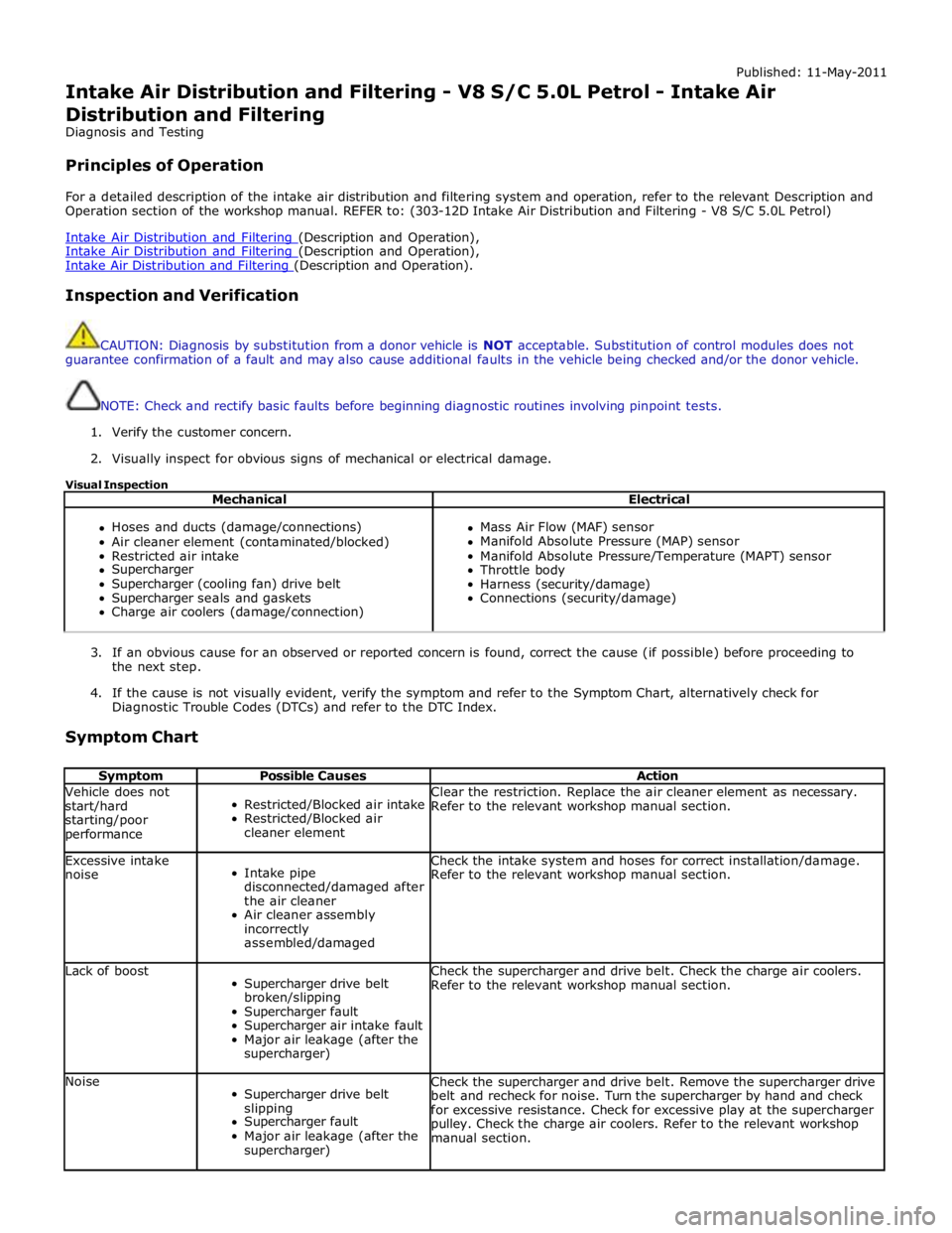
Symptom Possible Causes Action Vehicle does not
start/hard
starting/poor
performance
Restricted/Blocked air intake
Restricted/Blocked air
cleaner element Clear the restriction. Replace the air cleaner element as necessary.
Refer to the relevant workshop manual section. Excessive intake
noise
Intake pipe
disconnected/damaged after
the air cleaner
Air cleaner assembly
incorrectly
assembled/damaged Check the intake system and hoses for correct installation/damage.
Refer to the relevant workshop manual section. Lack of boost
Supercharger drive belt
broken/slipping
Supercharger fault
Supercharger air intake fault
Major air leakage (after the
supercharger) Check the supercharger and drive belt. Check the charge air coolers.
Refer to the relevant workshop manual section. Noise
Supercharger drive belt
slipping
Supercharger fault
Major air leakage (after the
supercharger) Check the supercharger and drive belt. Remove the supercharger drive
belt and recheck for noise. Turn the supercharger by hand and check
for excessive resistance. Check for excessive play at the supercharger
pulley. Check the charge air coolers. Refer to the relevant workshop
manual section.
Page 1301 of 3039
Published: 11-May-2011
Intake Air Distribution and Filtering - V8 S/C 5.0L Petrol - Air Cleaner
Element
Removal and Installation
Removal
NOTES:
Removal steps in this procedure may contain installation details.
Some variation in the illustrations may occur, but the essential information is always correct.
1. NOTE: Left-hand shown, right-hand similar.
2. NOTE: Left-hand shown, right-hand similar. www.JagDocs.com
Page 1303 of 3039
Published: 11-May-2011
Intake Air Distribution and Filtering - V8 S/C 5.0L Petrol - Air Cleaner LH
Removal and Installation
Removal
NOTE: Removal steps in this procedure may contain installation details.
1.
2.
3.
Page 1306 of 3039
Published: 11-May-2011
Intake Air Distribution and Filtering - V8 S/C 5.0L Petrol - Air Cleaner RH
Removal and Installation
Removal
NOTE: Removal steps in this procedure may contain installation details.
1.
2.
3. www.JagDocs.com
Page 1309 of 3039
Published: 11-May-2011
Intake Air Distribution and Filtering - V8 S/C 5.0L Petrol - Air Cleaner Outlet Pipe LH
Removal and Installation
Removal
NOTE: Removal steps in this procedure may contain installation details.
1.
Installation
1. To install, reverse the removal procedure.
Page 1310 of 3039
Published: 11-May-2011
Intake Air Distribution and Filtering - V8 S/C 5.0L Petrol - Air Cleaner Outlet Pipe RH
Removal and Installation
Removal
NOTE: Removal steps in this procedure may contain installation details.
1.
Installation
1. To install, reverse the removal procedure.
Page 1311 of 3039
Published: 11-May-2011
Intake Air Distribution and Filtering - V8 S/C 5.0L Petrol - Air Cleaner Outlet Pipe T-Connector
Removal and Installation
Removal
NOTE: Removal steps in this procedure may contain installation details.
1. Refer to: Engine Cover - V8 5.0L Petrol/V8 S/C 5.0L Petrol (501-05 Interior Trim and Ornamentation, Removal and Installation).
Installation
2. Torque: 10 Nm
1. To install, reverse the removal procedure. www.JagDocs.com