Page 1181 of 3039

to deliver the correct mass of fuel to the combustion chambers.
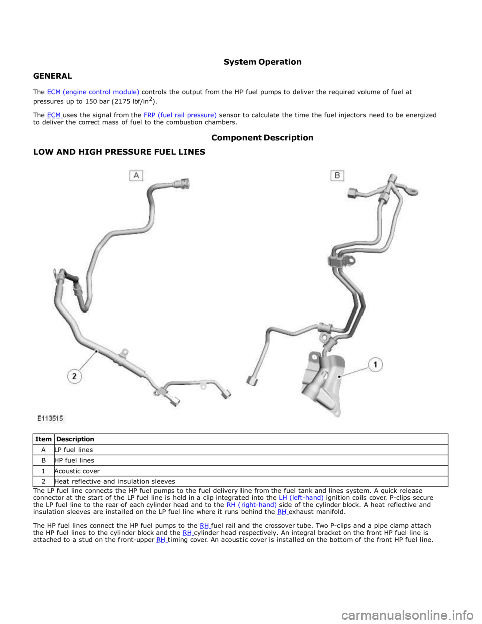
LOW AND HIGH PRESSURE FUEL LINES Component Description
Item Description A LP fuel lines B HP fuel lines 1 Acoustic cover 2 Heat reflective and insulation sleeves The LP fuel line connects the HP fuel pumps to the fuel delivery line from the fuel tank and lines system. A quick release
connector at the start of the LP fuel line is held in a clip integrated into the LH (left-hand) ignition coils cover. P-clips secure
the LP fuel line to the rear of each cylinder head and to the RH (right-hand) side of the cylinder block. A heat reflective and
insulation sleeves are installed on the LP fuel line where it runs behind the RH exhaust manifold.
The HP fuel lines connect the HP fuel pumps to the RH fuel rail and the crossover tube. Two P-clips and a pipe clamp attach the HP fuel lines to the cylinder block and the RH cylinder head respectively. An integral bracket on the front HP fuel line is attached to a stud on the front-upper RH timing cover. An acoustic cover is installed on the bottom of the front HP fuel line.
Page 1184 of 3039
1 LH fuel rail 2 Crossover tube 3 RH fuel rail 4 FRP sensor 5 Fuel injector (8 off) The fuel rails and crossover tube are made from stainless steel. Bolts attach each fuel rail to the related cylinder head. The
crossover tube connects the front high pressure line to the LH fuel rail, which ensures there is equal pressure in the two fuel rails. Four P-clips attach the crossover tube to the intercooler-tank top.
The rear of the RH fuel rail incorporates a threaded boss for installation of the FRP sensor. FUEL RAILS AND CROSSOVER TUBE
Page 1185 of 3039
RH fuel rail. The FRP sensor is screwed into a threaded boss in the fuel rail. A flying lead and three pin connector provides the interface with the engine harness.
The FRP sensor contains a steel diaphragm fitted with strain gages, which are incorporated into a Wheatstone bridge. The output from the Wheatstone bridge is processed by the ECM to derive a pressure value.
FUEL INJECTORS
The fuel injectors spray fuel from the fuel rail directly into the combustion chambers. The fuel injectors are installed close to
the center of the combustion chambers, between the inlet and exhaust valves and next to the spark plug.
The fuel injectors are a push fit in the fuel rails and the cylinder heads. On each fuel injector, a rubber O-ring seals the head of
the fuel injector in the fuel rail. A teflon ring seals the nozzle of the fuel injector in the cylinder head. A clamp locks each fuel
injector to the fuel rail. FUEL RAIL PRESSURE SENSOR
Page 1197 of 3039
4. CAUTION: If the original fuel injector is being installed, the original
fuel injector clamp must installed with the fuel injector it was removed
with.
5. CAUTION: If a new cylinder head has been installed then the special
tool 310-200-02 without the thread must be used to install the fuel rail.
Special Tool(s): 310-200-01, 310-200-02 www.JagDocs.com
Page 1210 of 3039
5. CAUTION: If a new cylinder head has been installed then the special tool
310-200-02 without the thread must be used to install the fuel rail.
Special Tool(s): 310-200-01, 310-200-02
6. CAUTIONS:
Make sure that the area around the open fuel injector ports are clean
and free of foreign material and lubricant prior to installing the fuel injector.
When Installing the fuel injector(s), make sure that the Teflon seal is
clean and free of foreign material and lubricant.
7. CAUTIONS:
If new fuel injectors are installed, a new injector clamp must be
installed
Make sure that the fuel injector is aligned and installed into the fuel
rail correctly, as noted in the removal step.
Tighten the fuel rail retaining bolts a turn at a time until the correct
torque is achieved.
NOTE: Lubricate the fuel injector O-ring seals with clean engine oil.
Torque: 20 Nm
8. NOTE: LH shown RH similar.
Special Tool(s): 310-200-01, 310-200-02
Page 1274 of 3039

GENERAL System Operation
The ignition coils are supplied with electrical power from the battery via a 250 A megafuse in the BJB (battery junction box)
and the ignition relay in the EJB (engine junction box). The control signal for the ignition relay is supplied by the CJB (central
junction box).
The ECM (engine control module) sends a separate signal to each ignition coil to trigger the power stage switching. The ECM calculates the dwell time from the battery voltage and engine speed, to ensure a constant energy level is produced in the
secondary coil each time the power stage is switched. This ensures sufficient spark energy is available without excessive
primary current flow, which avoids overheating and damage to the ignition coils.
The ECM calculates the ignition timing for individual cylinders from: Engine speed
Camshaft position
Engine load
Engine temperature
The knock control function
The shift control function
The idle speed control function.
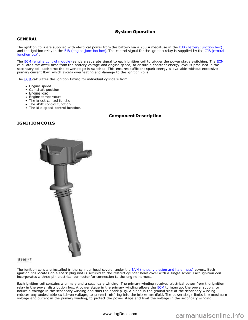
IGNITION COILS Component Description
The ignition coils are installed in the cylinder head covers, under the NVH (noise, vibration and harshness) covers. Each
ignition coil locates on a spark plug and is secured to the related cylinder head cover with a single screw. Each ignition coil
incorporates a three pin electrical connector for connection to the engine harness.
Each ignition coil contains a primary and a secondary winding. The primary winding receives electrical power from the ignition
relay in the power distribution box. A power stage in the primary winding allows the ECM to interrupt the power supply, to induce a voltage in the secondary winding and thus the spark plug. A diode in the ground side of the secondary winding
reduces any undesirable switch-on voltage, to prevent misfiring into the intake manifold. The power stage limits the maximum
voltage and current in the primary winding, to protect the power stage and limit the voltage in the secondary winding. www.JagDocs.com
Page 1281 of 3039
PARTLOADBREATHERComponentDescription
ItemDescription1Flexiblehose2Baffleplate3Oildrain4PCV(positivecrankcaseventilation)valves5OilseparatorThepartloadbreathercomprisesan oilseparator,twoPCV(positivecrankcaseventilation) valvesand aflexiblehose.Theoil
separatorandthePCVvalvesareinstalledinthetopoftheRH(right-hand)cylinderhead cover.TheflexiblehoseconnectstheRHcylinderheadcovertotheinletoftheSC(supercharger).Theoilseparatorisinstalledinachannelin thetopofthecylinderheadcover.Abaffleplate,whichincorporatesagasinlet
andanoildrain,isinstalledoverthechannel.ThetwoPCVvalvesareinstalledontheoutsideofthecylinderheadcoverandconnectedinparallelinthegasoutletfromthechannelto theflexiblehose.ThePCVvalvespreventreverseflowintothecylinderheadcoverwhen thereisminimaldepressionintheinletoftheSC.
Page 1282 of 3039
1 Flexible hose 2 Two-way valve 3 Oil drain 4 Baffle plate 5 Oil separator The full load breather consists of an oil separator, a two-way valve and a flexible hose. The oil separator and the two-way valve
are installed in the top of the LH (left-hand) cylinder head cover. The flexible hose connects the LH cylinder head cover to the LH air duct of the intake air distribution and filtering system.
The oil separator is installed in a channel in the top of the cylinder head cover. A baffle plate, which incorporates a gas inlet
and an oil drain, is installed over the channel. The two-way valve is installed in the gas outlet from the channel. The two-way
valve prevents reverse flow into the cylinder head cover when there is minimal depression in the air duct. FULL LOAD BREATHER