2010 JAGUAR XFR Control module
[x] Cancel search: Control modulePage 2077 of 3039
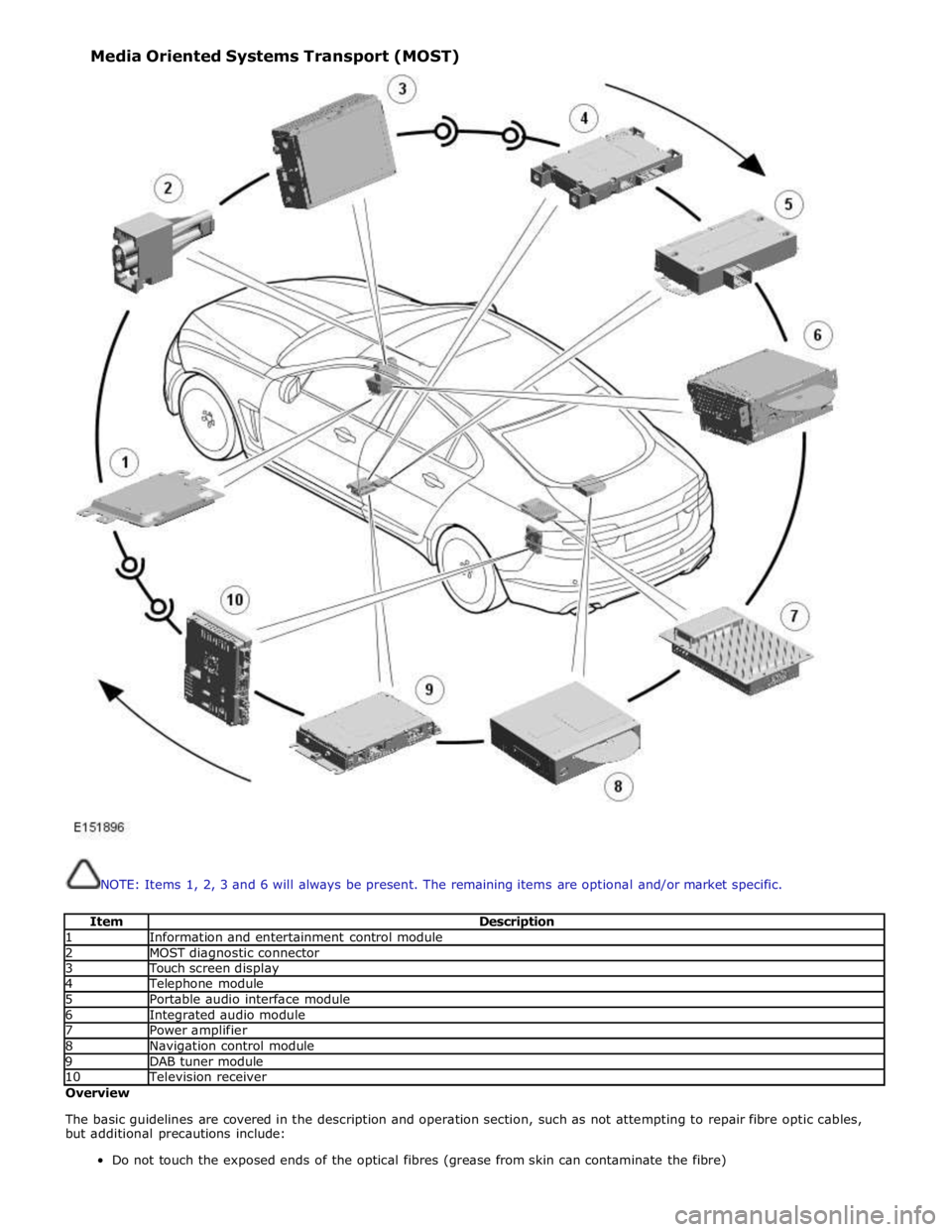
NOTE: Items 1, 2, 3 and 6 will always be present. The remaining items are optional and/or market specific.
Item Description 1 Information and entertainment control module 2 MOST diagnostic connector 3 Touch screen display 4 Telephone module 5 Portable audio interface module 6 Integrated audio module 7 Power amplifier 8 Navigation control module 9 DAB tuner module 10 Television receiver Overview
The basic guidelines are covered in the description and operation section, such as not attempting to repair fibre optic cables,
but additional precautions include:
Do not touch the exposed ends of the optical fibres (grease from skin can contaminate the fibre) Media Oriented Systems Transport (MOST)
Page 2078 of 3039
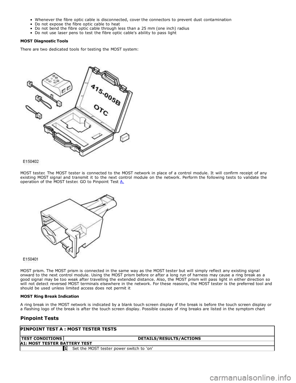
MOST prism. The MOST prism is connected in the same way as the MOST tester but will simply reflect any existing signal
onward to the next control module. Using the MOST prism before or after a long run of harness may cause a ring break as a
good signal may be too weak after travelling the extended distance. Also, the MOST prism will pass light in either direction so
will not detect reversed MOST terminals elsewhere in the network. For these reasons, the MOST tester is the preferred tool and
should be used unless limited access does not permit it
MOST Ring Break Indication
A ring break in the MOST network is indicated by a blank touch screen display if the break is before the touch screen display or
a flashing logo of the break is after the touch screen display. Possible causes of ring breaks are listed in the symptom chart
Pinpoint Tests
PINPOINT TEST A : MOST TESTER TESTS TEST CONDITIONS DETAILS/RESULTS/ACTIONS A1: MOST TESTER BATTERY TEST 1 Set the MOST tester power switch to 'on'
Page 2080 of 3039
NOTE: When connecting the MOST tester, use the 2+0 or 2+4 socket as appropriate and set the connector selector
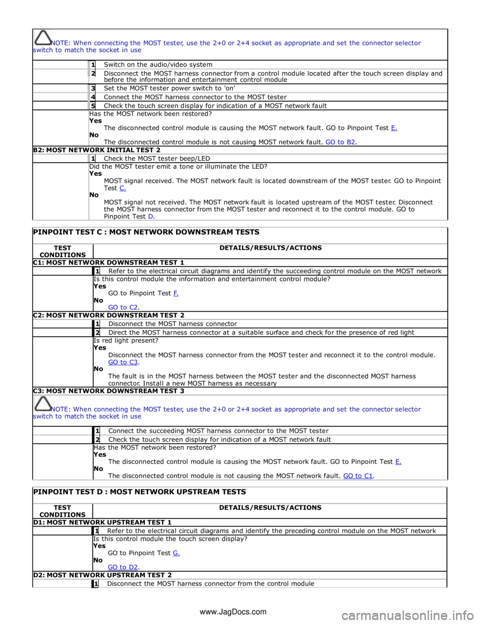
switch to match the socket in use 1 Switch on the audio/video system 2 Disconnect the MOST harness connector from a control module located after the touch screen display and before the information and entertainment control module 3 Set the MOST tester power switch to 'on' 4 Connect the MOST harness connector to the MOST tester 5 Check the touch screen display for indication of a MOST network fault Has the MOST network been restored? Yes
The disconnected control module is causing the MOST network fault. GO to Pinpoint Test E. No
The disconnected control module is not causing MOST network fault. GO to B2. B2: MOST NETWORK INITIAL TEST 2 1 Check the MOST tester beep/LED Did the MOST tester emit a tone or illuminate the LED? Yes
MOST signal received. The MOST network fault is located downstream of the MOST tester. GO to Pinpoint
Test C. No
MOST signal not received. The MOST network fault is located upstream of the MOST tester. Disconnect
the MOST harness connector from the MOST tester and reconnect it to the control module. GO to Pinpoint Test D.
PINPOINT TEST C : MOST NETWORK DOWNSTREAM TESTS TEST
CONDITIONS DETAILS/RESULTS/ACTIONS C1: MOST NETWORK DOWNSTREAM TEST 1 1 Refer to the electrical circuit diagrams and identify the succeeding control module on the MOST network Is this control module the information and entertainment control module?
Yes
GO to Pinpoint Test F. No
GO to C2. C2: MOST NETWORK DOWNSTREAM TEST 2 1 Disconnect the MOST harness connector 2 Direct the MOST harness connector at a suitable surface and check for the presence of red light Is red light present?
Yes
Disconnect the MOST harness connector from the MOST tester and reconnect it to the control module.
GO to C3. No
The fault is in the MOST harness between the MOST tester and the disconnected MOST harness
connector. Install a new MOST harness as necessary C3: MOST NETWORK DOWNSTREAM TEST 3
NOTE: When connecting the MOST tester, use the 2+0 or 2+4 socket as appropriate and set the connector selector
switch to match the socket in use 1 Connect the succeeding MOST harness connector to the MOST tester 2 Check the touch screen display for indication of a MOST network fault Has the MOST network been restored?
Yes
The disconnected control module is causing the MOST network fault. GO to Pinpoint Test E. No
The disconnected control module is not causing the MOST network fault. GO to C1.
PINPOINT TEST D : MOST NETWORK UPSTREAM TESTS TEST
CONDITIONS DETAILS/RESULTS/ACTIONS D1: MOST NETWORK UPSTREAM TEST 1 1 Refer to the electrical circuit diagrams and identify the preceding control module on the MOST network Is this control module the touch screen display?
Yes
GO to Pinpoint Test G. No
GO to D2. D2: MOST NETWORK UPSTREAM TEST 2 1 Disconnect the MOST harness connector from the control module www.JagDocs.com
Page 2081 of 3039
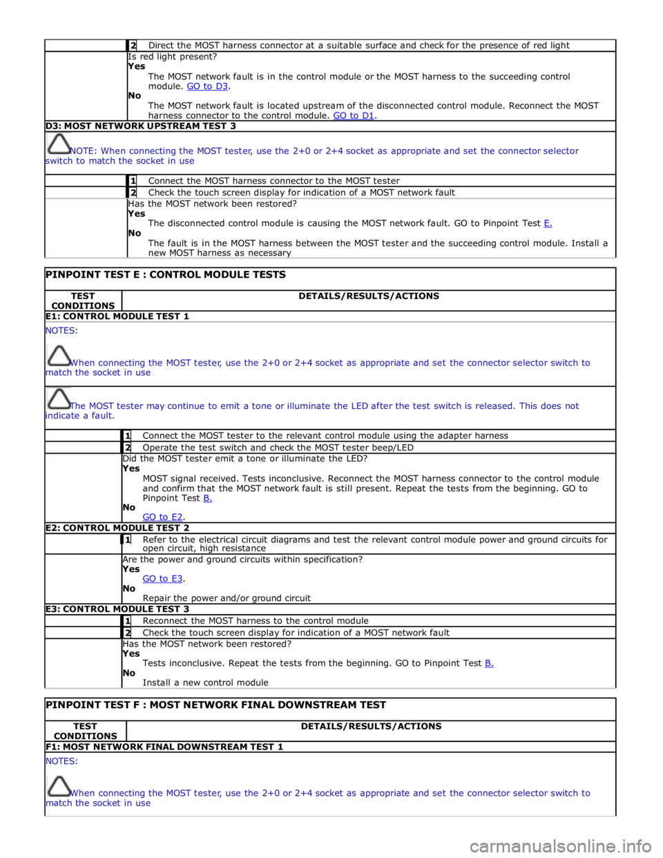
2 Direct the MOST harness connector at a suitable surface and check for the presence of red light Is red light present?
Yes
The MOST network fault is in the control module or the MOST harness to the succeeding control
module. GO to D3. No
The MOST network fault is located upstream of the disconnected control module. Reconnect the MOST
harness connector to the control module. GO to D1. D3: MOST NETWORK UPSTREAM TEST 3
NOTE: When connecting the MOST tester, use the 2+0 or 2+4 socket as appropriate and set the connector selector
switch to match the socket in use 1 Connect the MOST harness connector to the MOST tester 2 Check the touch screen display for indication of a MOST network fault Has the MOST network been restored?
Yes
The disconnected control module is causing the MOST network fault. GO to Pinpoint Test E. No
The fault is in the MOST harness between the MOST tester and the succeeding control module. Install a
new MOST harness as necessary
PINPOINT TEST E : CONTROL MODULE TESTS TEST
CONDITIONS DETAILS/RESULTS/ACTIONS E1: CONTROL MODULE TEST 1 NOTES:
When connecting the MOST tester, use the 2+0 or 2+4 socket as appropriate and set the connector selector switch to
match the socket in use
The MOST tester may continue to emit a tone or illuminate the LED after the test switch is released. This does not
indicate a fault. 1 Connect the MOST tester to the relevant control module using the adapter harness 2 Operate the test switch and check the MOST tester beep/LED Did the MOST tester emit a tone or illuminate the LED? Yes
MOST signal received. Tests inconclusive. Reconnect the MOST harness connector to the control module
and confirm that the MOST network fault is still present. Repeat the tests from the beginning. GO to
Pinpoint Test B. No
GO to E2. E2: CONTROL MODULE TEST 2 1 Refer to the electrical circuit diagrams and test the relevant control module power and ground circuits for open circuit, high resistance Are the power and ground circuits within specification? Yes
GO to E3. No
Repair the power and/or ground circuit E3: CONTROL MODULE TEST 3 1 Reconnect the MOST harness to the control module 2 Check the touch screen display for indication of a MOST network fault Has the MOST network been restored? Yes
Tests inconclusive. Repeat the tests from the beginning. GO to Pinpoint Test B. No
Install a new control module
PINPOINT TEST F : MOST NETWORK FINAL DOWNSTREAM TEST TEST
CONDITIONS DETAILS/RESULTS/ACTIONS F1: MOST NETWORK FINAL DOWNSTREAM TEST 1 NOTES:
When connecting the MOST tester, use the 2+0 or 2+4 socket as appropriate and set the connector selector switch to
match the socket in use
Page 2082 of 3039
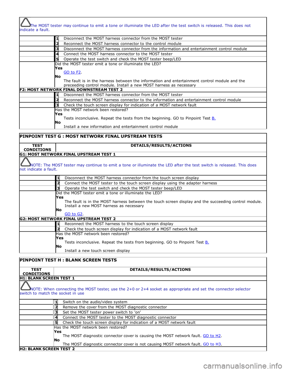
The MOST tester may continue to emit a tone or illuminate the LED after the test switch is released. This does not
indicate a fault. 1 Disconnect the MOST harness connector from the MOST tester 2 Reconnect the MOST harness connector to the control module 3 Disconnect the MOST harness connector from the information and entertainment control module 4 Connect the MOST harness connector to the MOST tester 5 Operate the test switch and check the MOST tester beep/LED Did the MOST tester emit a tone or illuminate the LED? Yes
GO to F2. No
The fault is in the harness between the information and entertainment control module and the preceeding control module. Install a new MOST harness as necessary F2: MOST NETWORK FINAL DOWNSTREAM TEST 2 1 Disconnect the MOST harness connector from the MOST tester 2 Reconnect the MOST harness connector to the information and entertainment control module 3 Check the touch screen display for indication of a MOST network fault Has the MOST network been restored? Yes
Tests inconclusive. Repeat the tests from the beginning. GO to Pinpoint Test B. No
Install a new information and entertainment control module
PINPOINT TEST G : MOST NETWORK FINAL UPSTREAM TESTS TEST
CONDITIONS DETAILS/RESULTS/ACTIONS G1: MOST NETWORK FINAL UPSTREAM TEST 1
NOTE: The MOST tester may continue to emit a tone or illuminate the LED after the test switch is released. This does
not indicate a fault. 1 Disconnect the MOST harness connector from the touch screen display 2 Connect the MOST tester to the touch screen display using the adapter harness 3 Operate the test switch and check the MOST tester beep/LED Did the MOST tester emit a tone or illuminate the LED? Yes
The fault is in the MOST harness between the touch screen display and the succeeding control module.
Install a new MOST harness as necessary
No
GO to G2. G2: MOST NETWORK FINAL UPSTREAM TEST 2 1 Reconnect the MOST harness to the touch screen display 2 Check the touch screen display for indication of a MOST network fault Has the MOST network been restored? Yes
Tests inconclusive. Repeat the tests from beginning. GO to Pinpoint Test B. No
Install a new touch screen display
PINPOINT TEST H : BLANK SCREEN TESTS TEST
CONDITIONS DETAILS/RESULTS/ACTIONS H1: BLANK SCREEN TEST 1
NOTE: When connecting the MOST tester, use the 2+0 or 2+4 socket as appropriate and set the connector selector
switch to match the socket in use 1 Switch on the audio/video system 2 Remove the cover from the MOST diagnostic connector 3 Set the MOST tester power switch to 'on' 4 Connect the MOST tester to the MOST diagnostic connector 5 Check the touch screen display for indication of a MOST network fault Has the MOST network been restored? Yes
The MOST diagnostic connector cover is causing the MOST network fault. GO to H2. No
The MOST diagnostic connector cover is not causing MOST network fault. GO to H3. H2: BLANK SCREEN TEST 2
Page 2083 of 3039
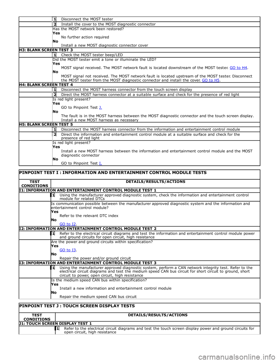
1 Disconnect the MOST tester 2 Install the cover to the MOST diagnostic connector Has the MOST network been restored? Yes
No further action required
No
Install a new MOST diagnostic connector cover H3: BLANK SCREEN TEST 3 1 Check the MOST tester beep/LED Did the MOST tester emit a tone or illuminate the LED? Yes
MOST signal received. The MOST network fault is located downstream of the MOST tester. GO to H4. No
MOST signal not received. The MOST network fault is located upstream of the MOST tester. Disconnect
the MOST tester from the MOST diagnostic connector and install the cover. GO to H5. H4: BLANK SCREEN TEST 4 1 Disconnect the MOST harness connector from the touch screen display 2 Direct the MOST harness connector at a suitable surface and check for the presence of red light Is red light present? Yes
GO to Pinpoint Test J. No
The fault is in the MOST harness between the MOST diagnostic connector and the touch screen display.
Install a new MOST harness as necessary H5: BLANK SCREEN TEST 5 1 Disconnect the MOST harness connector from the information and entertainment control module 2 Direct the information and entertainment control module at a suitable surface and check for the presence of red light Is red light present? Yes
Install a new MOST harness between the information and entertainment control module and the MOST
diagnostic connector
No
GO to Pinpoint Test I.
PINPOINT TEST I : INFORMATION AND ENTERTAINMENT CONTROL MODULE TESTS TEST
CONDITIONS DETAILS/RESULTS/ACTIONS I1: INFORMATION AND ENTERTAINMENT CONTROL MODULE TEST 1 1 Using the manufacturer approved diagnostic system, check the information and entertainment control module for related DTCs Is communication possible between the manufacturer approved diagnostic system and the information and
entertainment control module? Yes
Refer to the relevant DTC index
No
GO to I2. I2: INFORMATION AND ENTERTAINMENT CONTROL MODULE TEST 2 1 Refer to the electrical circuit diagrams and test the information and entertainment control module power and ground circuits for open circuit, high resistance Are the power and ground circuits within specification? Yes
GO to I3. No
Repair the power and/or ground circuit I3: INFORMATION AND ENTERTAINMENT CONTROL MODULE TEST 3 1 Using the manufacturer approved diagnostic system, perform a CAN network integrity test. Refer to the electrical circuit diagrams and test the medium speed CAN bus circuit for short circuit to ground, short
circuit to power, open circuit, high resistance Is the medium speed CAN bus within specification? Yes
Install a new information and entertainment control module
No
Repair the medium speed CAN bus circuit
PINPOINT TEST J : TOUCH SCREEN DISPLAY TESTS TEST
CONDITIONS DETAILS/RESULTS/ACTIONS J1: TOUCH SCREEN DISPLAY TEST 1 1 Refer to the electrical circuit diagrams and test the touch screen display power and ground circuits for open circuit, high resistance
Page 2084 of 3039
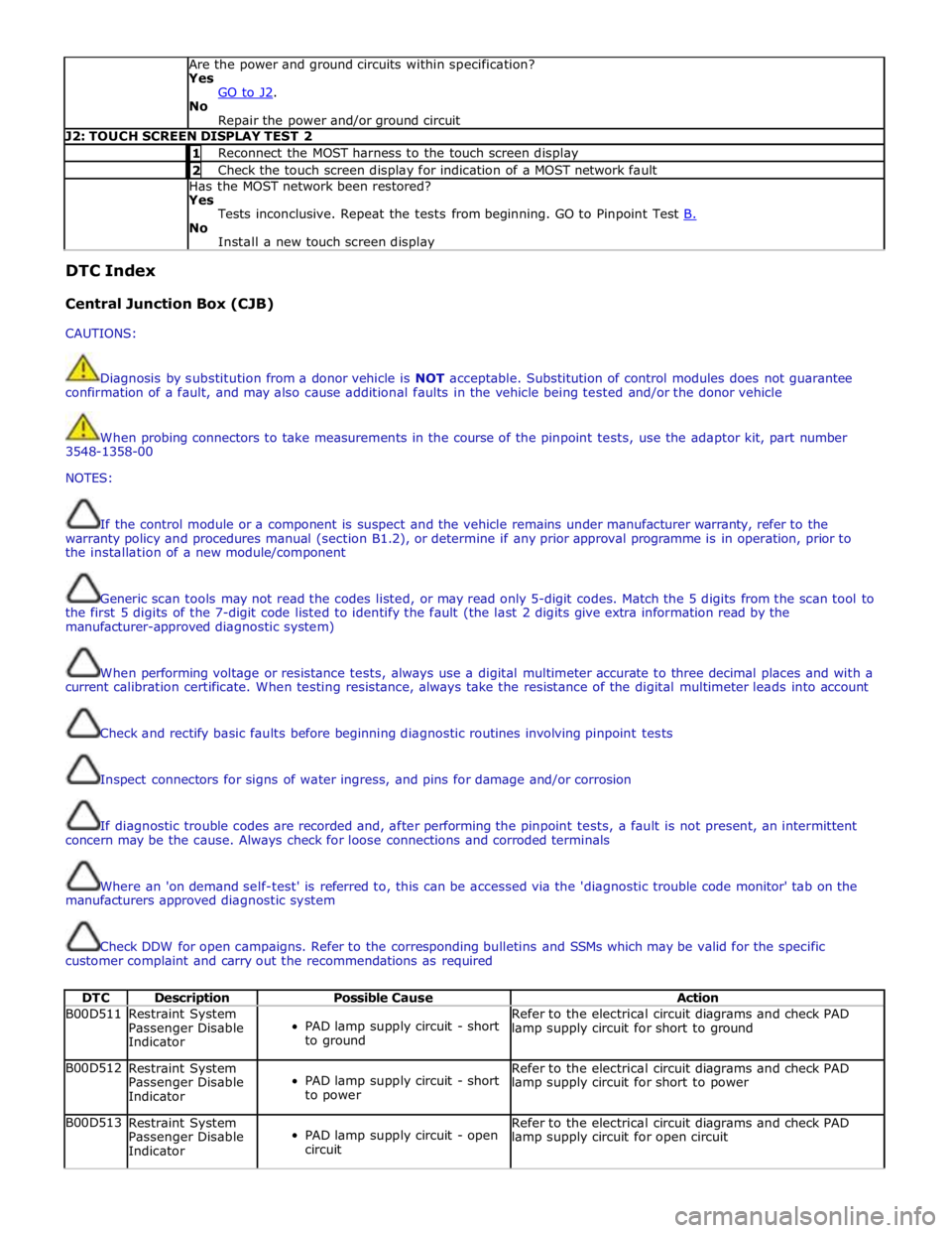
Are the power and ground circuits within specification?
Yes
GO to J2. No
Repair the power and/or ground circuit J2: TOUCH SCREEN DISPLAY TEST 2 1 Reconnect the MOST harness to the touch screen display 2 Check the touch screen display for indication of a MOST network fault Has the MOST network been restored?
Yes
Tests inconclusive. Repeat the tests from beginning. GO to Pinpoint Test B. No
Install a new touch screen display DTC Index
Central Junction Box (CJB)
CAUTIONS:
Diagnosis by substitution from a donor vehicle is NOT acceptable. Substitution of control modules does not guarantee
confirmation of a fault, and may also cause additional faults in the vehicle being tested and/or the donor vehicle
When probing connectors to take measurements in the course of the pinpoint tests, use the adaptor kit, part number
3548-1358-00
NOTES:
If the control module or a component is suspect and the vehicle remains under manufacturer warranty, refer to the
warranty policy and procedures manual (section B1.2), or determine if any prior approval programme is in operation, prior to
the installation of a new module/component
Generic scan tools may not read the codes listed, or may read only 5-digit codes. Match the 5 digits from the scan tool to
the first 5 digits of the 7-digit code listed to identify the fault (the last 2 digits give extra information read by the
manufacturer-approved diagnostic system)
When performing voltage or resistance tests, always use a digital multimeter accurate to three decimal places and with a
current calibration certificate. When testing resistance, always take the resistance of the digital multimeter leads into account
Check and rectify basic faults before beginning diagnostic routines involving pinpoint tests
Inspect connectors for signs of water ingress, and pins for damage and/or corrosion
If diagnostic trouble codes are recorded and, after performing the pinpoint tests, a fault is not present, an intermittent
concern may be the cause. Always check for loose connections and corroded terminals
Where an 'on demand self-test' is referred to, this can be accessed via the 'diagnostic trouble code monitor' tab on the
manufacturers approved diagnostic system
Check DDW for open campaigns. Refer to the corresponding bulletins and SSMs which may be valid for the specific
customer complaint and carry out the recommendations as required
DTC Description Possible Cause Action B00D511
Restraint System
Passenger Disable
Indicator
PAD lamp supply circuit - short
to ground Refer to the electrical circuit diagrams and check PAD
lamp supply circuit for short to ground B00D512
Restraint System
Passenger Disable
Indicator
PAD lamp supply circuit - short
to power Refer to the electrical circuit diagrams and check PAD
lamp supply circuit for short to power B00D513
Restraint System
Passenger Disable
Indicator
PAD lamp supply circuit - open
circuit Refer to the electrical circuit diagrams and check PAD
lamp supply circuit for open circuit
Page 2086 of 3039

DTC Description Possible Cause Action B108A12 Start Button
Start/Stop switch analogue
input circuits 1 or 2 - short to
power Refer to the electrical circuit diagrams and check
Start/Stop switch analogue input circuits 1 and 2 for
short to power B109512 Wiper On/Off Relay
Wiper On/Off relay control
circuit - short to power Carry out any pinpoint tests associated with this DTC
using the manufacturer approved diagnostic system.
Refer to the electrical circuit diagrams and check wiper
On/Off relay control circuit for short to power B109514 Wiper On/Off Relay
Wiper On/Off relay control
circuit - short to ground, open
circuit Refer to the electrical circuit diagrams and check wiper
On/Off relay control circuit for short to ground, open
circuit B109612
Wiper High/Low
Relay
Wiper Fast/Slow relay control
circuit - short to power Carry out any pinpoint tests associated with this DTC
using the manufacturer approved diagnostic system.
Refer to the electrical circuit diagrams and check wiper
Fast/Slow relay control circuit for short to power B109614
Wiper High/Low
Relay
Wiper Fast/Slow relay control
circuit - short to ground, open
circuit Refer to the electrical circuit diagrams and check wiper
Fast/Slow relay control circuit for short to ground, open
circuit B109712
Heated Windshield
Relay
Heated windshield relay control
circuit - short to power Carry out any pinpoint tests associated with this DTC
using the manufacturer approved diagnostic system.
Refer to the electrical circuit diagrams and check heated
windshield relay control circuit for short to power B109714
Heated Windshield
Relay
Heated windshield relay control
circuit - short to ground, open
circuit Refer to the electrical circuit diagrams and check heated
windshield relay control circuit for short to ground, open
circuit B10A612 Main Light Switch
Master light switch signal from
roof header console circuit -
short to power Refer to the electrical circuit diagrams and check master
light switch signal from roof header console circuit for
short to power B10A623 Main Light Switch
Master light switch signal from
roof header console signal
stuck low. Switch is read as ON
for too long a time Carry out any pinpoint tests associated with this DTC
using the manufacturer approved diagnostic system.
Refer to the electrical circuit diagrams and check master
light switch signal from roof header console for short to
ground B10AD09 Rain Sensor
Component failures Carry out any pinpoint tests associated with this DTC
using the manufacturer approved diagnostic system.
Suspect the rain/light sensor, check and install a new
sensor as required B10AD11 Rain Sensor
Rain/light sensor power circuit -
short to ground Carry out any pinpoint tests associated with this DTC
using the manufacturer approved diagnostic system.
Refer to the electrical circuit diagrams and check rain/light sensor power circuit for short to ground B10AD96 Rain Sensor
Component internal failure Suspect the rain/light sensor, check and install a new
sensor as required B10E511
PCM Wake-up
Signal
ECM wake-up signal circuit -
short to ground Refer to the electrical circuit diagrams and check ECM
wake-up signal circuit for short to ground B10E512
PCM Wake-up
Signal
ECM wake-up signal circuit -
short to power Refer to the electrical circuit diagrams and check ECM
wake-up signal circuit for short to power B10E513
PCM Wake-up
Signal
ECM wake-up signal circuit -
open circuit Refer to the electrical circuit diagrams and check ECM
wake-up signal circuit for open circuit B10F111 Key In Switch
Keyless vehicle module, key IN
status circuit - short to ground Carry out any pinpoint tests associated with this DTC
using the manufacturer approved diagnostic system.
Refer to the electrical circuit diagrams and check keyless
vehicle module, key IN status circuit for short to ground B10F112 Key In Switch
Keyless vehicle module, key IN
status circuit - short to power Refer to the electrical circuit diagrams and check keyless
vehicle module, key IN status circuit for short to power B10F113 Key In Switch
Keyless vehicle module, key IN
status circuit - open circuit Refer to the electrical circuit diagrams and check keyless
vehicle module, key IN status circuit for open circuit