2010 JAGUAR XFR heating
[x] Cancel search: heatingPage 2315 of 3039

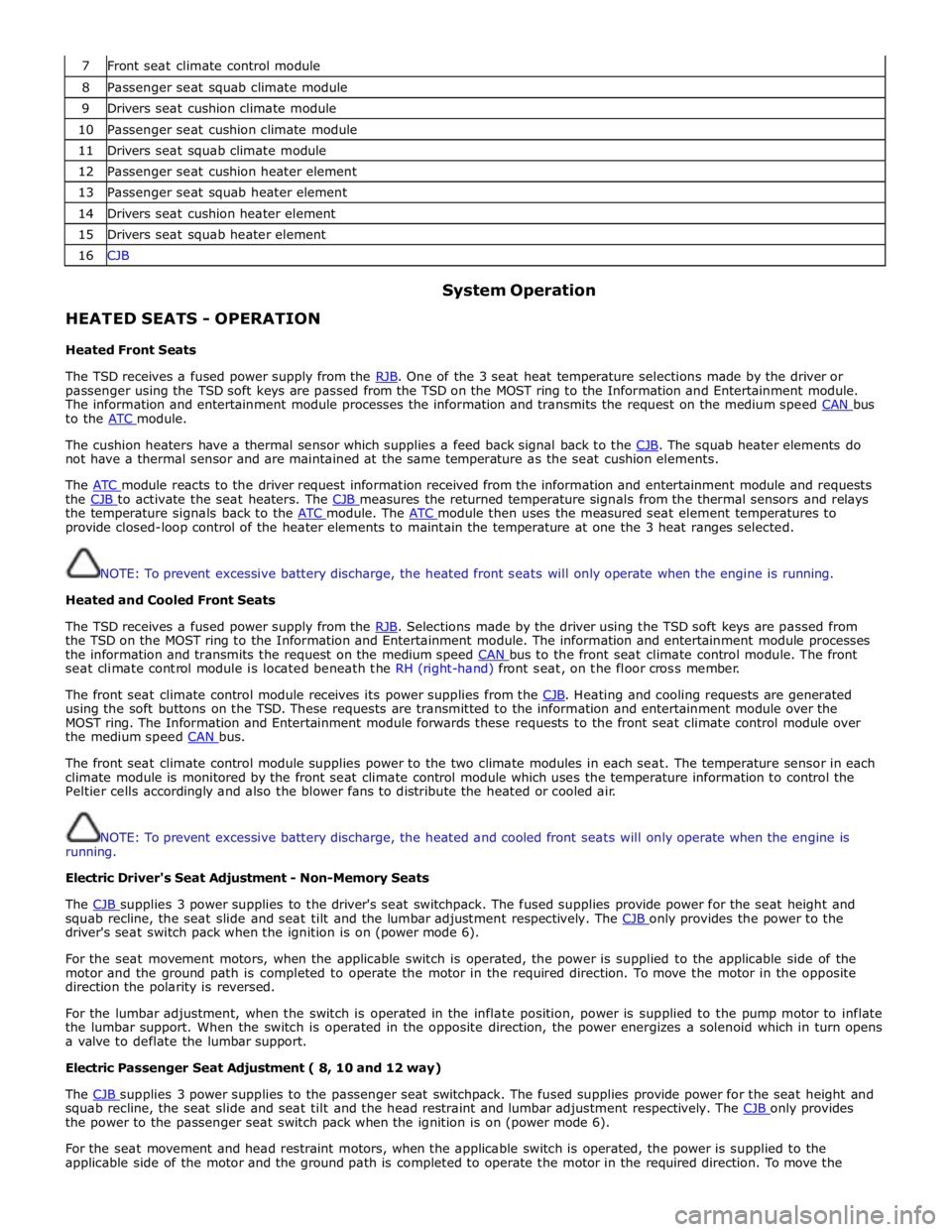
7 Front seat climate control module 8 Passenger seat squab climate module 9 Drivers seat cushion climate module 10 Passenger seat cushion climate module 11 Drivers seat squab climate module 12 Passenger seat cushion heater element 13 Passenger seat squab heater element 14 Drivers seat cushion heater element 15 Drivers seat squab heater element 16 CJB
HEATED SEATS - OPERATION
Heated Front Seats System Operation
The TSD receives a fused power supply from the RJB. One of the 3 seat heat temperature selections made by the driver or passenger using the TSD soft keys are passed from the TSD on the MOST ring to the Information and Entertainment module.
The information and entertainment module processes the information and transmits the request on the medium speed CAN bus to the ATC module.
The cushion heaters have a thermal sensor which supplies a feed back signal back to the CJB. The squab heater elements do not have a thermal sensor and are maintained at the same temperature as the seat cushion elements.
The ATC module reacts to the driver request information received from the information and entertainment module and requests the CJB to activate the seat heaters. The CJB measures the returned temperature signals from the thermal sensors and relays the temperature signals back to the ATC module. The ATC module then uses the measured seat element temperatures to provide closed-loop control of the heater elements to maintain the temperature at one the 3 heat ranges selected.
NOTE: To prevent excessive battery discharge, the heated front seats will only operate when the engine is running.
Heated and Cooled Front Seats
The TSD receives a fused power supply from the RJB. Selections made by the driver using the TSD soft keys are passed from the TSD on the MOST ring to the Information and Entertainment module. The information and entertainment module processes
the information and transmits the request on the medium speed CAN bus to the front seat climate control module. The front seat climate control module is located beneath the RH (right-hand) front seat, on the floor cross member.
The front seat climate control module receives its power supplies from the CJB. Heating and cooling requests are generated using the soft buttons on the TSD. These requests are transmitted to the information and entertainment module over the
MOST ring. The Information and Entertainment module forwards these requests to the front seat climate control module over
the medium speed CAN bus.
The front seat climate control module supplies power to the two climate modules in each seat. The temperature sensor in each
climate module is monitored by the front seat climate control module which uses the temperature information to control the
Peltier cells accordingly and also the blower fans to distribute the heated or cooled air.
NOTE: To prevent excessive battery discharge, the heated and cooled front seats will only operate when the engine is
running.
Electric Driver's Seat Adjustment - Non-Memory Seats
The CJB supplies 3 power supplies to the driver's seat switchpack. The fused supplies provide power for the seat height and squab recline, the seat slide and seat tilt and the lumbar adjustment respectively. The CJB only provides the power to the driver's seat switch pack when the ignition is on (power mode 6).
For the seat movement motors, when the applicable switch is operated, the power is supplied to the applicable side of the
motor and the ground path is completed to operate the motor in the required direction. To move the motor in the opposite
direction the polarity is reversed.
For the lumbar adjustment, when the switch is operated in the inflate position, power is supplied to the pump motor to inflate
the lumbar support. When the switch is operated in the opposite direction, the power energizes a solenoid which in turn opens
a valve to deflate the lumbar support.
Electric Passenger Seat Adjustment ( 8, 10 and 12 way)
The CJB supplies 3 power supplies to the passenger seat switchpack. The fused supplies provide power for the seat height and squab recline, the seat slide and seat tilt and the head restraint and lumbar adjustment respectively. The CJB only provides the power to the passenger seat switch pack when the ignition is on (power mode 6).
For the seat movement and head restraint motors, when the applicable switch is operated, the power is supplied to the
applicable side of the motor and the ground path is completed to operate the motor in the required direction. To move the
Page 2316 of 3039

supplies provide power for the movement motors in addition to the driver's seat switch pack. Power is only supplied to the
driver's seat module and the driver's seat switch pack when the ignition is on (power mode 6).
The driver's seat switch pack is connected to the driver's seat module by a LIN bus for the seat movement switches. Any selection for seat movement generates a message which is passed via the LIN to the driver's seat module. The seat module processes the request and operates the applicable seat function as required using the power supplies from the CJB.
Each seat motor contains a Hall position sensor. The sensor sends a feedback signal to the driver's seat module. The signal is
used for memory store and memory recall functions.
The lumbar adjustment switch on the driver's seat switch pack is wired direct to the lumbar pump and solenoids. The switch,
when moved to the inflate position for either the upper or lower inflatable cushion cell, provides a power supply to the lumbar
pump and simultaneously activates the applicable inflate solenoid valve. When the switch is released the pump stops and the
solenoid valve closes trapping the air in the inflatable cushion. When the switch is moved to the deflate position for either the
upper or lower inflatable cushion cell, power is supplied to the applicable deflate solenoid valve which opens to allow the air in
the cushion to escape. When the switch is released, the valve is closed and the remaining air in the cushion is retained.
FRONT SEATS - DESCRIPTION Component Description
The table below highlights the features available for each seating option.
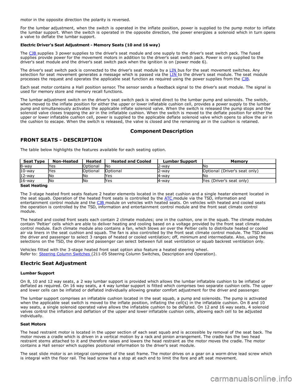
Seat Type Non-Heated Heated Heated and Cooled Lumbar Support Memory 8-way Yes Optional No 2-way No 10-way Yes Optional Optional 2-way Optional (Driver's seat only) 12-way No No Yes 4-way No 16-way No No Yes 4-way Yes (Driver's seat only) Seat Heating
The 3-stage heated front seats feature 2 heater elements located in the seat cushion and a single heater element located in
the seat squab. Operation of the heated front seats is controlled by the ATC module via the TSD, information and entertainment control module and the CJB module on vehicles with heated seats. On vehicles with heated and cooled seats the operation is controlled by the TSD, information and entertainment control module and the front seat climate control
module.
The heated and cooled front seats each contain 2 climate modules; one in the cushion, one in the squab. The climate modules
contain 'Peltier' cells which are able to deliver heating and cooling based on a voltage provided by the front seat climate
control module. Each climate module also contains a fan, which blows air over the Peltier cells to distribute heated or cooled
air via liners in the seat cushion and squab. The fan is also controlled by the front seat climate control module. The TSD allows
the driver and passenger to select 3 ranges of heated or cooled ventilation; off, minimum and intermediate. Also, using the
selections on the TSD, the driver and passenger can select between full seat ventilation or squab backrest ventilation only.
Vehicles fitted with the 3-stage heated front seat option also feature a heated steering wheel.
Refer to: Steering Column Switches (211-05 Steering Column Switches, Description and Operation).
Electric Seat Adjustment
Lumbar Support
On 8, 10 and 12 way seats, a 2 way lumbar support is provided which allows the lumbar inflatable cushion to be inflated or
deflated as required. On 16 way seats, a 4 way lumbar support is fitted which comprises two separate cushion cells. The upper
and lower cells can be inflated or deflated individually allowing greater comfort adjustment for the driver and passenger.
The lumbar support comprises an inflatable cushion located in the seat squab, a pump and solenoids. The pump is activated
when the applicable seat switch is moved to the inflate position, inflating the cell(s) in the inflatable cushion. On 8 and 10
way seats, a single solenoid operated valve allows the inflatable cushion to be deflated. On 12 and 16 way seats, 4 solenoid
valves control the inflation and deflation of the upper and lower inflatable cushion cells, allowing each cell to be adjusted
individually.
Seat Motors
The head restraint motor is located in the upper section of each seat squab and is accessible by removal of the seat back. The
motor moves a cradle which is driven in a vertical motion by a rack and pinion arrangement. The cradle has the two head
restraint stems attached to it and therefore raises and lowers the head restraint as the motor moves the cradle. The motor
contains a Hall sensor which supplies positional information to the driver's seat module.
The seat slide motor is an integral component of the seat frame. The motor drives on a gear on a worm drive lead screw which
is integral with the floor rail. The lead screw has a stop at each end to limit the fore and aft seat movement.
Page 2713 of 3039

- Sealing welded seams.
- Applying underbody protection.
- Sticking damping matting in place.
- Filling cavities with cavity wax.
- Cavity wax (after painting).
Panel Beating
Fundamentals of panel beating
Before carrying out any sectional replacements or complete replacements of body panels, always check carefully
whether the damaged panel(s) can be rectified by panel beating.
Panel beating is usually the easiest and most economical method of repairing a damaged panel.
Examples of applications of different panel beating techniques:
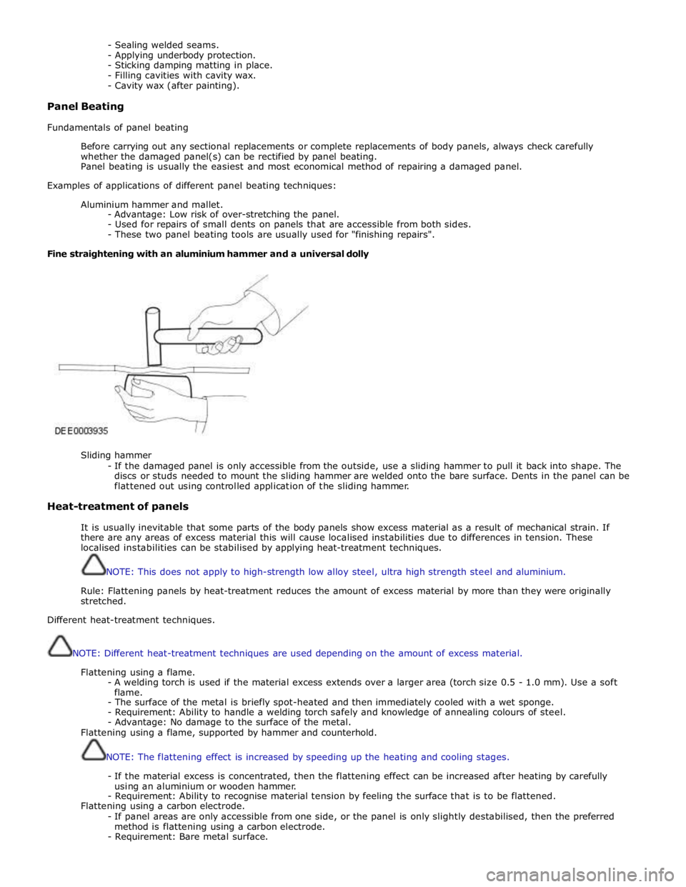
Aluminium hammer and mallet.
- Advantage: Low risk of over-stretching the panel.
- Used for repairs of small dents on panels that are accessible from both sides.
- These two panel beating tools are usually used for "finishing repairs".
Fine straightening with an aluminium hammer and a universal dolly
Sliding hammer
- If the damaged panel is only accessible from the outside, use a sliding hammer to pull it back into shape. The
discs or studs needed to mount the sliding hammer are welded onto the bare surface. Dents in the panel can be
flattened out using controlled application of the sliding hammer.
Heat-treatment of panels
It is usually inevitable that some parts of the body panels show excess material as a result of mechanical strain. If
there are any areas of excess material this will cause localised instabilities due to differences in tension. These
localised instabilities can be stabilised by applying heat-treatment techniques.
NOTE: This does not apply to high-strength low alloy steel, ultra high strength steel and aluminium.
Rule: Flattening panels by heat-treatment reduces the amount of excess material by more than they were originally
stretched.
Different heat-treatment techniques.
NOTE: Different heat-treatment techniques are used depending on the amount of excess material.
Flattening using a flame.
- A welding torch is used if the material excess extends over a larger area (torch size 0.5 - 1.0 mm). Use a soft
flame.
- The surface of the metal is briefly spot-heated and then immediately cooled with a wet sponge.
- Requirement: Ability to handle a welding torch safely and knowledge of annealing colours of steel.
- Advantage: No damage to the surface of the metal.
Flattening using a flame, supported by hammer and counterhold.
NOTE: The flattening effect is increased by speeding up the heating and cooling stages.
- If the material excess is concentrated, then the flattening effect can be increased after heating by carefully
using an aluminium or wooden hammer.
- Requirement: Ability to recognise material tension by feeling the surface that is to be flattened.
Flattening using a carbon electrode.
- If panel areas are only accessible from one side, or the panel is only slightly destabilised, then the preferred
method is flattening using a carbon electrode.
- Requirement: Bare metal surface.
Page 2714 of 3039

- Disadvantage: Scarring and hardening of the surface.
Flattening using a copper electrode.
- Small, sharp dents that face outwards can be worked on with a copper electrode.
Flattening using a flame and body files.
NOTE: When applied correctly, this method can be used with all the attached parts still in place (roof headlining,
wiring harnesses etc.).
- Small, soft dents (only slight stretching): Working at the edges of the dent in an inward spiral pattern, the dent
is heated with an oxyacetylene torch (torch size 1 - 2 mm, excess gas flame) to approx. 250° C.
- Working rapidly with a body file extracts heat from the edge area until the dent is flattened. Preferably alternate
between two files. This increases the amount of heat that can be extracted.
Safety measures
The electronic control modules (ECM) fitted to vehicles make it advisable to follow suitable precautions prior to carrying
out welding repair operations. Harsh conditions of heat and vibration may be generated during these operations which
could cause damage to the modules. In particular, it is essential to follow the appropriate precautions when
disconnecting or removing the airbag RCM.
Do not allow electronic modules or lines to come into contact with the ground connection or the welding electrode.
Seat belt anchorages are a safety critical. When making repairs in these areas, it is essential to follow design
specifications. Note that extra strength low alloy steel may be used for seat belt anchorages. Where possible, the
original production assembly should be used, complete with its seat belt anchorages, or the cut line should be so
arranged that the original seat belt anchorage is not disturbed.
All welds within 250mm (9.842) of seat belt anchorages must be carefully checked for weld quality, including spacing of
spot welds.
Remove the battery before carrying out welding work in its vicinity.
Utmost care must be taken when welding near the fuel tank or other components that contain fuel. If the tank filler
neck or a fuel line must be detached to allow access for welding work, then the fuel tank must be drained and removed.
Never weld, on components of a filled air conditioning system. The same applies if there is a risk of the air conditioning
system heating up.
Connect the ground connection of the electrical welder directly to the part that is to be welded. Make sure that there
are no electrically insulating parts between the ground connection and the welding point.
Adjacent vehicle parts and adjacent vehicles must be shielded against flying sparks and heat.
Pedestrian protection system
The pedestrian protection system is designed to mitigate injuries in a pedestrian collision with the vehicle. It does this by
utilizing a pair of pyrotechnic actuators to lift the hood away from the engine, creating a cushioned impact between the
pedestrian and the vehicle. It is essential that any repair or replacement operations do not affect the safe working of the
system.
For additional information, refer to: Pedestrian Protection System (501-20C Pedestrian Protection System, Description and Operation).
Resistance spot welding
Where resistance spot welds have been used in production, they must be reproduced with new spot welds in replacement
where possible. All such reproduction spot welds should be spaced 25 to 30mm apart.
Setting up the equipment and co-ordinating the welding parameters.
Equipment:
- Follow the equipment manufacturer's instructions for the equipment settings.
- Select the correct electrode arms (as short as possible).
- Align the electrode arms and tips exactly.
- Electrode tips should be convex (rough shaping with a file, fine shaping with a sanding block).
Body:
- Make sure that the flanges to be joined lie perfectly flat to one another.
- Prepare a bare metal joint surface (inside and outside).
Notes on technique/method:
- Carry out a test weld on a sample piece of the material coated in welding paste.
- If any metal parts are located between the electrode arms then there will be a loss of induction and therefore
power (adjust current setting).
- The power needs to be adjusted for high-strength low alloy steel.
- Repeated welding on old welding points often leads to poor quality welds.
- Keep the electrode tips as near as possible to an angle of 90° to the contact surface.
- Keep the pressure on the electrodes for a short period after finishing the weld.
- The electrodes work best if their shape is convex. Clean the contact surface of the electrodes regularly.
Resistance spot welding panels where the total thickness is 3 mm or more
For all repairs to modern Jaguar vehicles, spot-welding equipment should be suitable for reliable welding of zinc-plated,
high-strength and high-tensile steels in three or more layers, up to 5 mm total thickness. If these requirements are not
fulfilled, plug welding must be used for safety reasons. The electrical specifications (current, resistance, heat) of the
spot-welding equipment have different validity, depending upon the type of equipment. Therefore, it is essential that the
manufacturer's instructions are observed with regard to the actual welding performance.
www.JagDocs.com
Page 2718 of 3039

Part N-umber
Body Repairs - Corrosion Protection - Corrosion Protection
Description and Operation
General Published: 11-May-2011
The corrosion protection provided in production must be carefully maintained and/or reproduced during and after body repair
work. It is only then that the long-term warranty against penetrative corrosion damage can be assured.
Only Jaguar original bodywork components and Jaguar approved repair materials, (sealer, paint etc.), are to be used for
bodywork repairs.
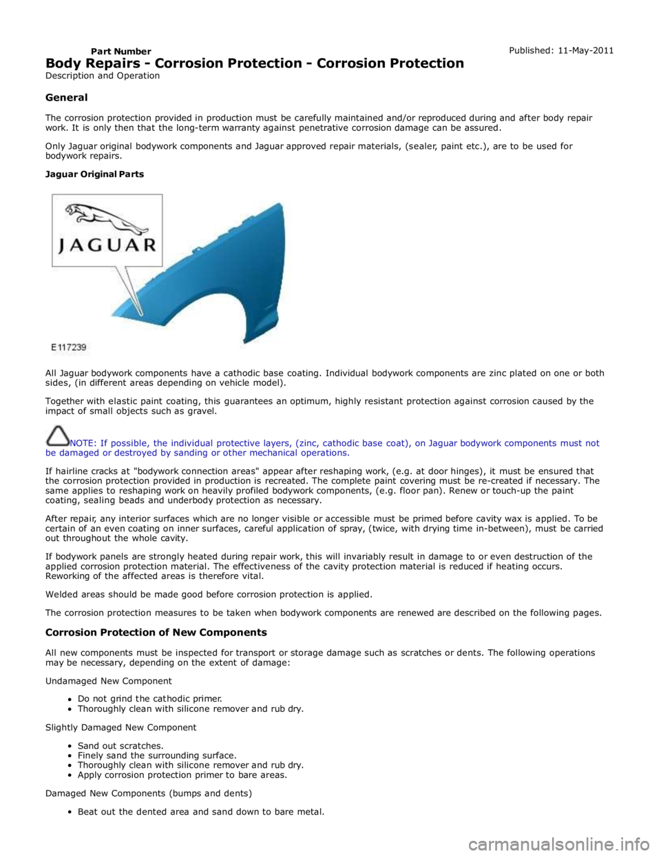
Jaguar Original Parts
All Jaguar bodywork components have a cathodic base coating. Individual bodywork components are zinc plated on one or both
sides, (in different areas depending on vehicle model).
Together with elastic paint coating, this guarantees an optimum, highly resistant protection against corrosion caused by the
impact of small objects such as gravel.
NOTE: If possible, the individual protective layers, (zinc, cathodic base coat), on Jaguar bodywork components must not
be damaged or destroyed by sanding or other mechanical operations.
If hairline cracks at "bodywork connection areas" appear after reshaping work, (e.g. at door hinges), it must be ensured that
the corrosion protection provided in production is recreated. The complete paint covering must be re-created if necessary. The
same applies to reshaping work on heavily profiled bodywork components, (e.g. floor pan). Renew or touch-up the paint
coating, sealing beads and underbody protection as necessary.
After repair, any interior surfaces which are no longer visible or accessible must be primed before cavity wax is applied. To be
certain of an even coating on inner surfaces, careful application of spray, (twice, with drying time in-between), must be carried
out throughout the whole cavity.
If bodywork panels are strongly heated during repair work, this will invariably result in damage to or even destruction of the
applied corrosion protection material. The effectiveness of the cavity protection material is reduced if heating occurs.
Reworking of the affected areas is therefore vital.
Welded areas should be made good before corrosion protection is applied.
The corrosion protection measures to be taken when bodywork components are renewed are described on the following pages.
Corrosion Protection of New Components
All new components must be inspected for transport or storage damage such as scratches or dents. The following operations
may be necessary, depending on the extent of damage:
Undamaged New Component
Do not grind the cathodic primer.
Thoroughly clean with silicone remover and rub dry.
Slightly Damaged New Component
Sand out scratches.
Finely sand the surrounding surface.
Thoroughly clean with silicone remover and rub dry.
Apply corrosion protection primer to bare areas.
Damaged New Components (bumps and dents)
Beat out the dented area and sand down to bare metal.