2010 JAGUAR XFR power steering fluid
[x] Cancel search: power steering fluidPage 740 of 3039

Power Steering - Power Steering - Component Location
Description and Operation
Published: 11-May-2011
POWER STEERING-COMPONENTLOCATION5.0LV8
ItemDescriptionNOTE:Naturallyaspirated5.0LV8shown,Supercharged5.0LV8similar1Powersteeringfluidcooler2Tie-rodend(2off)3Tie-rod(2off)4Powersteeringpump5Lowpressurefluidreturnhose6Powersteeringfluidreservoir7Feedpipetopump8Highpressurefeedpipetosteeringgear9Servotronictransducervalve10Valveunit11Mountingbolt(3off)12Steeringgear
Page 741 of 3039

compartment, forward of the front suspension housing.
On petrol engine vehicles, a fluid cooler is located in front of the engine cooling radiator. Diesel models do not have a fluid
cooler.
Servotronic 2 adds electronic control and speed sensitive steering to the steering gear. The Servotronic 2 feature provides easy
and comfortable steering operation when parking, improved 'road feel' at increased road speeds and adds an integrated,
positive center feel feature which optimises steering wheel torque during high speed driving. The Servotronic 2 system is
controlled by software which is incorporated into the instrument cluster. The software responds to road speed signals and
controls the power assistance via a transducer valve located on the steering gear valve housing.
Page 743 of 3039

Torsion bar 19 Power steering fluid reservoir 20 Valve rotor 21 Reaction piston 22 Reaction chamber 23 Centering piece 24 Pressure relief/flow limiting valve 25 Power steering pump 26 Inner tie-rod 27 Pinion 28 Valve sleeve 29 Steering gear rack 30 Steering gear housing 31 Power assist cylinder - right 32 Piston 33 Power assist cylinder - left When the engine is started, the power steering pump draws fluid from the reservoir down the low pressure suction line. The
fluid passes through the pump and is delivered at pressure, via a hose, to the steering rack valve unit.
The pressurized fluid flows through a connecting bore in the valve and, via the feed fluid radial groove and the transverse
bores in the valve sleeve, passes to the feed fluid control groove of the valve rotor.
In the neutral (straight ahead) position , the fluid passes over the open feed fluid control edges to all valve sleeve axial
grooves. The fluid then passes through return fluid control edges and the return fluid grooves of the valve rotor, back to the
reservoir passes via the fluid cooler.
Simultaneously, the radial grooves of the valve and their associated pipes provide a connection the left and right power assist
cylinders.
Power Steering in Right Turn Position
Page 744 of 3039

1 Return fluid control groove 2 Radial groove 3 Feed fluid control groove 4 Radial groove 5 Axial groove 6 Feed fluid control edge 7 Feed fluid radial groove 8 Return fluid control edge 9 Return fluid chamber 10 Cut-off valve 11 Radial groove 12 Servotronic transducer valve 13 Feed fluid radial groove 14 Radial groove 15 Orifice 16 Balls 17 Compression spring 18 Torsion bar 19 Power steering fluid reservoir 20 Valve rotor 21 Reaction piston 22 Reaction chamber 23 Centering piece 24 Pressure relief/flow limiting valve 25 Power steering pump 26 Inner tie-rod 27 Pinion 28 Valve sleeve 29 Steering gear rack 30 Steering gear housing 31 Power assist cylinder - right 32 Piston 33 Power assist cylinder - left When the steering wheel is turned to the right, the steering rack and piston moves to the left in the piston bore. The valve
rotor is rotated to the right (clockwise) and pressurized fluid is directed over the further opened feed fluid control edges and to
the associated axial grooves, the radial groove and via an external pipe to the left power assist cylinder chamber. The pressure
applied to the piston from the left power assist cylinder chamber provides the hydraulic assistance.
An adaptable pressure build-up is achieved by the partially or fully closed feed fluid control edges restricting or preventing a
connection between the fluid pressure inlet and the other axial grooves connected to the radial groove.
Simultaneously, the fluid pressure outlet to the pressurized axial grooves are restricted or partially restricted by the closing
return fluid control edges. The fluid displaced by the piston from the right power assist cylinder chamber, flows through an
external pipe to the radial grooves. From there the fluid passes to the associated axial grooves and on to the return fluid
control grooves, via the further opened return fluid control edges.
The return flow of fluid to the reservoir passes via interconnecting bores which lead to the return fluid chamber. When the
steering wheel is turned to the left the operating sequence is as above but the pressure is applied to the opposite side of the
piston.
Servotronic Operation
The Servotronic software contains a number of steering maps which are selected via the car configuration file depending on the
vehicle mode and tire fitment.
If a failure of the Servotronic valve or software occurs, the system will suspend Servotronic assistance and only normal power
steering wheel be available. Fault codes relating to the fault are stored, but no warning lamps are illuminated and the driver
may be aware of the steering being 'heavier' than usual.
When the vehicle is manoeuvred into and out of a parking space (or other similar manoeuvre), the Servotronic software uses
road speed data from the ABS module to determine the vehicle speed, which in this case will be slow or stationary. The
Servotronic software analyses the signals and outputs an appropriate control current to the Servotronic transducer valve. The
Servotronic valve closes and prevents fluid flowing from the feed fluid radial groove to the reaction chamber. An orifice also
Page 747 of 3039

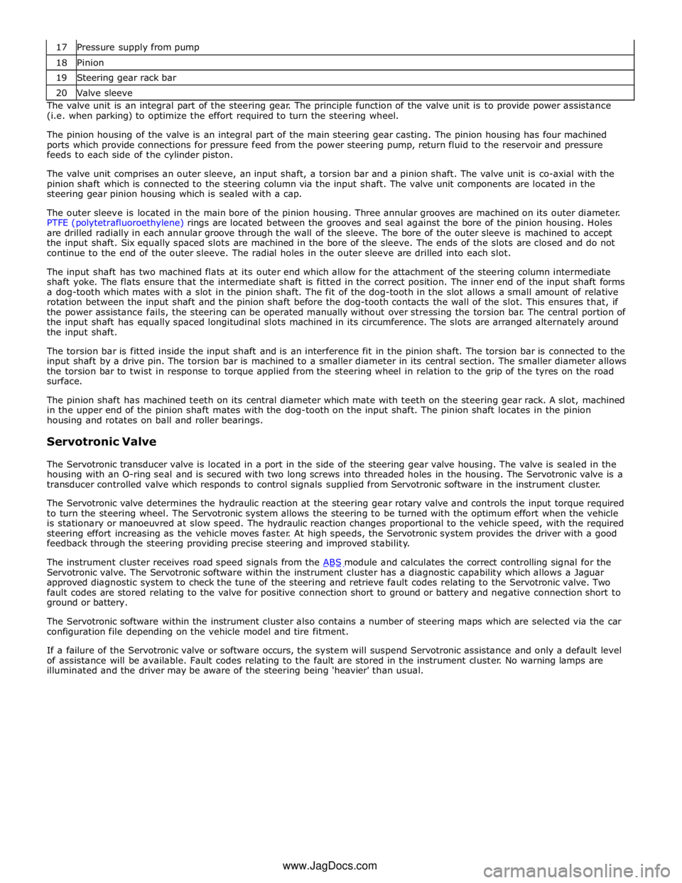
18 Pinion 19 Steering gear rack bar 20 Valve sleeve The valve unit is an integral part of the steering gear. The principle function of the valve unit is to provide power assistance
(i.e. when parking) to optimize the effort required to turn the steering wheel.
The pinion housing of the valve is an integral part of the main steering gear casting. The pinion housing has four machined
ports which provide connections for pressure feed from the power steering pump, return fluid to the reservoir and pressure
feeds to each side of the cylinder piston.
The valve unit comprises an outer sleeve, an input shaft, a torsion bar and a pinion shaft. The valve unit is co-axial with the
pinion shaft which is connected to the steering column via the input shaft. The valve unit components are located in the
steering gear pinion housing which is sealed with a cap.
The outer sleeve is located in the main bore of the pinion housing. Three annular grooves are machined on its outer diameter.
PTFE (polytetrafluoroethylene) rings are located between the grooves and seal against the bore of the pinion housing. Holes
are drilled radially in each annular groove through the wall of the sleeve. The bore of the outer sleeve is machined to accept
the input shaft. Six equally spaced slots are machined in the bore of the sleeve. The ends of the slots are closed and do not
continue to the end of the outer sleeve. The radial holes in the outer sleeve are drilled into each slot.
The input shaft has two machined flats at its outer end which allow for the attachment of the steering column intermediate
shaft yoke. The flats ensure that the intermediate shaft is fitted in the correct position. The inner end of the input shaft forms
a dog-tooth which mates with a slot in the pinion shaft. The fit of the dog-tooth in the slot allows a small amount of relative
rotation between the input shaft and the pinion shaft before the dog-tooth contacts the wall of the slot. This ensures that, if
the power assistance fails, the steering can be operated manually without over stressing the torsion bar. The central portion of
the input shaft has equally spaced longitudinal slots machined in its circumference. The slots are arranged alternately around
the input shaft.
The torsion bar is fitted inside the input shaft and is an interference fit in the pinion shaft. The torsion bar is connected to the
input shaft by a drive pin. The torsion bar is machined to a smaller diameter in its central section. The smaller diameter allows
the torsion bar to twist in response to torque applied from the steering wheel in relation to the grip of the tyres on the road
surface.
The pinion shaft has machined teeth on its central diameter which mate with teeth on the steering gear rack. A slot, machined
in the upper end of the pinion shaft mates with the dog-tooth on the input shaft. The pinion shaft locates in the pinion
housing and rotates on ball and roller bearings.
Servotronic Valve
The Servotronic transducer valve is located in a port in the side of the steering gear valve housing. The valve is sealed in the
housing with an O-ring seal and is secured with two long screws into threaded holes in the housing. The Servotronic valve is a
transducer controlled valve which responds to control signals supplied from Servotronic software in the instrument cluster.
The Servotronic valve determines the hydraulic reaction at the steering gear rotary valve and controls the input torque required
to turn the steering wheel. The Servotronic system allows the steering to be turned with the optimum effort when the vehicle
is stationary or manoeuvred at slow speed. The hydraulic reaction changes proportional to the vehicle speed, with the required
steering effort increasing as the vehicle moves faster. At high speeds, the Servotronic system provides the driver with a good
feedback through the steering providing precise steering and improved stability.
The instrument cluster receives road speed signals from the ABS module and calculates the correct controlling signal for the Servotronic valve. The Servotronic software within the instrument cluster has a diagnostic capability which allows a Jaguar
approved diagnostic system to check the tune of the steering and retrieve fault codes relating to the Servotronic valve. Two
fault codes are stored relating to the valve for positive connection short to ground or battery and negative connection short to
ground or battery.
The Servotronic software within the instrument cluster also contains a number of steering maps which are selected via the car
configuration file depending on the vehicle model and tire fitment.
If a failure of the Servotronic valve or software occurs, the system will suspend Servotronic assistance and only a default level
of assistance will be available. Fault codes relating to the fault are stored in the instrument cluster. No warning lamps are
illuminated and the driver may be aware of the steering being 'heavier' than usual.
www.JagDocs.com
Page 749 of 3039

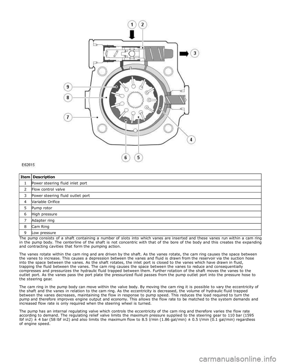
1 Power steering fluid inlet port 2 Flow control valve 3 Power steering fluid outlet port 4 Variable Orifice 5 Pump rotor 6 High pressure 7 Adapter ring 8 Cam Ring 9 Low pressure The pump consists of a shaft containing a number of slots into which vanes are inserted and these vanes run within a cam ring
in the pump body. The centerline of the shaft is not concentric with that of the bore of the body and this creates the expanding
and contracting cavities that form the pumping action.
The vanes rotate within the cam ring and are driven by the shaft. As the vanes rotate, the cam ring causes the space between
the vanes to increase. This causes a depression between the vanes and fluid is drawn from the reservoir via the suction hose
into the space between the vanes. As the shaft rotates, the inlet port is closed to the vanes which have drawn in fluid,
trapping the fluid between the vanes. The cam ring causes the space between the vanes to reduce and consequentially
compresses and pressurizes the hydraulic fluid trapped between them. Further rotation of the shaft moves the vanes to the
outlet port. As the vanes pass the port plate the pressurized fluid passes from the pump outlet port into the pressure hose to
the steering gear.
The cam ring in the pump body can move within the valve body. By moving the cam ring it is possible to vary the eccentricity of
the shaft and the vanes in relation to the cam ring. As the eccentricity is decreased, the volume of hydraulic fluid trapped
between the vanes decreases, maintaining the flow in response to pump speed. This reduces the load required to turn the
pump and therefore improves engine output and economy. This allows the flow rate to be matched to the system demands and
increased flow rate is only required when the steering wheel is turned.
The pump has an internal regulating valve which controls the eccentricity of the cam ring and therefore varies the flow rate
according to demand. The regulating relief valve limits the maximum pressure supplied to the steering gear to 110 bar (1595
lbf in2) ± 4 bar (58 lbf in2) and also limits the maximum flow to 8.5 l/min (1.86 gal/min) ± 0.5 l/min (0.1 gal/min) regardless
of engine speed.
Page 750 of 3039

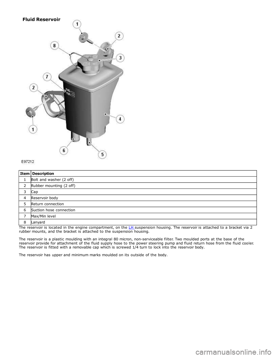
1 Bolt and washer (2 off) 2 Rubber mounting (2 off) 3 Cap 4 Reservoir body 5 Return connection 6 Suction hose connection 7 Max/Min level 8 Lanyard The reservoir is located in the engine compartment, on the LH suspension housing. The reservoir is attached to a bracket via 2 rubber mounts, and the bracket is attached to the suspension housing.
The reservoir is a plastic moulding with an integral 80 micron, non-serviceable filter. Two moulded ports at the base of the
reservoir provide for attachment of the fluid supply hose to the power steering pump and fluid return hose from the fluid cooler.
The reservoir is fitted with a removable cap which is screwed 1/4 turn to lock into the reservoir body.
The reservoir has upper and minimum marks moulded on its outside of the body. Fluid Reservoir
Page 755 of 3039

8. CAUTION: Air tools MUST NOT be used on steering
column bolts.
Disconnect the lower steering column from the steering
gear.
Remove and discard the bolt.
9. Release the power steering line support bracket.
10. CAUTIONS:
Before disconnecting or removing the components,
make sure the area around the joint faces and connections
are clean and dry. Plug open connections to prevent
contamination.
Cap the power steering line to prevent loses of fluid
and dirt ingress.
If power steering fluid is spilt on the paintwork, the
effected area must be immediately washed down with cold
water. Failure to follow this instruction may result in
damage to the vehicle.
NOTE: Some fluid spillage is inevitable during this
operation.
Disconnect the power steering feed and return fluid lines
from the steering gear.
Remove the bolt.
Position a container to collect spillage.
Remove and discard both O-ring seals.
11. Remove the steering gear.
Remove the 3 bolts.
Installation
1. To install, reverse the removal procedure.