2010 JAGUAR XFR fuse chart
[x] Cancel search: fuse chartPage 2328 of 3039

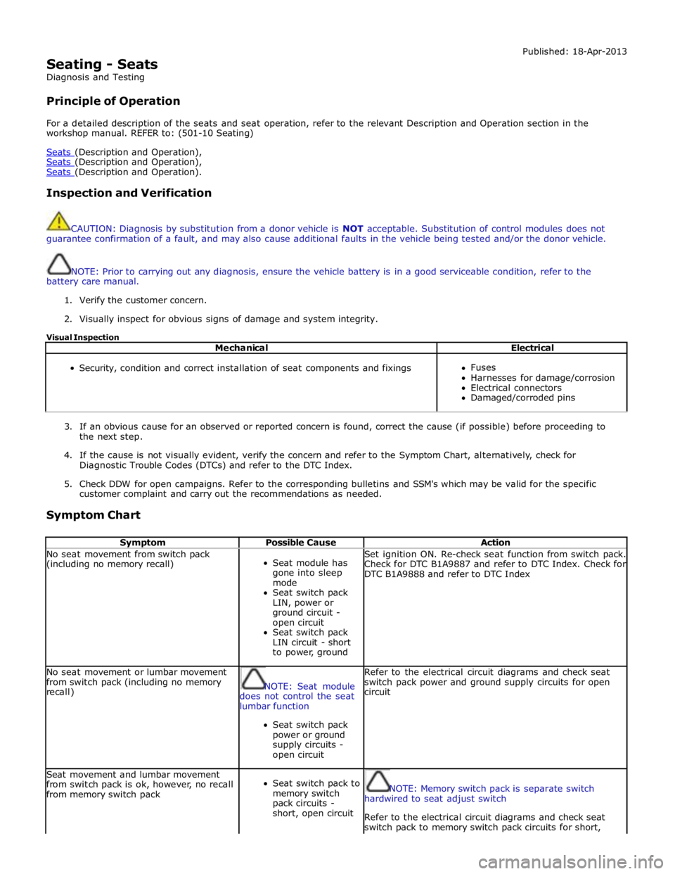
Seating - Seats
Diagnosis and Testing
Principle of Operation Published: 18-Apr-2013
For a detailed description of the seats and seat operation, refer to the relevant Description and Operation section in the
workshop manual. REFER to: (501-10 Seating)
Seats (Description and Operation), Seats (Description and Operation), Seats (Description and Operation).
Inspection and Verification
CAUTION: Diagnosis by substitution from a donor vehicle is NOT acceptable. Substitution of control modules does not
guarantee confirmation of a fault, and may also cause additional faults in the vehicle being tested and/or the donor vehicle.
NOTE: Prior to carrying out any diagnosis, ensure the vehicle battery is in a good serviceable condition, refer to the
battery care manual.
1. Verify the customer concern.
2. Visually inspect for obvious signs of damage and system integrity.
Visual Inspection
Mechanical Electrical
Security, condition and correct installation of seat components and fixings
Fuses
Harnesses for damage/corrosion
Electrical connectors
Damaged/corroded pins
3. If an obvious cause for an observed or reported concern is found, correct the cause (if possible) before proceeding to
the next step.
4. If the cause is not visually evident, verify the concern and refer to the Symptom Chart, alternatively, check for
Diagnostic Trouble Codes (DTCs) and refer to the DTC Index.
5. Check DDW for open campaigns. Refer to the corresponding bulletins and SSM's which may be valid for the specific
customer complaint and carry out the recommendations as needed.
Symptom Chart
Symptom Possible Cause Action No seat movement from switch pack
(including no memory recall)
Seat module has
gone into sleep
mode
Seat switch pack
LIN, power or
ground circuit -
open circuit
Seat switch pack
LIN circuit - short
to power, ground Set ignition ON. Re-check seat function from switch pack.
Check for DTC B1A9887 and refer to DTC Index. Check for
DTC B1A9888 and refer to DTC Index No seat movement or lumbar movement
from switch pack (including no memory
recall)
NOTE: Seat module
does not control the seat
lumbar function
Seat switch pack
power or ground
supply circuits -
open circuit Refer to the electrical circuit diagrams and check seat
switch pack power and ground supply circuits for open
circuit Seat movement and lumbar movement
from switch pack is ok, however, no recall
from memory switch pack
Seat switch pack to
memory switch
pack circuits -
short, open circuit
NOTE: Memory switch pack is separate switch
hardwired to seat adjust switch
Refer to the electrical circuit diagrams and check seat
switch pack to memory switch pack circuits for short,
Page 2495 of 3039

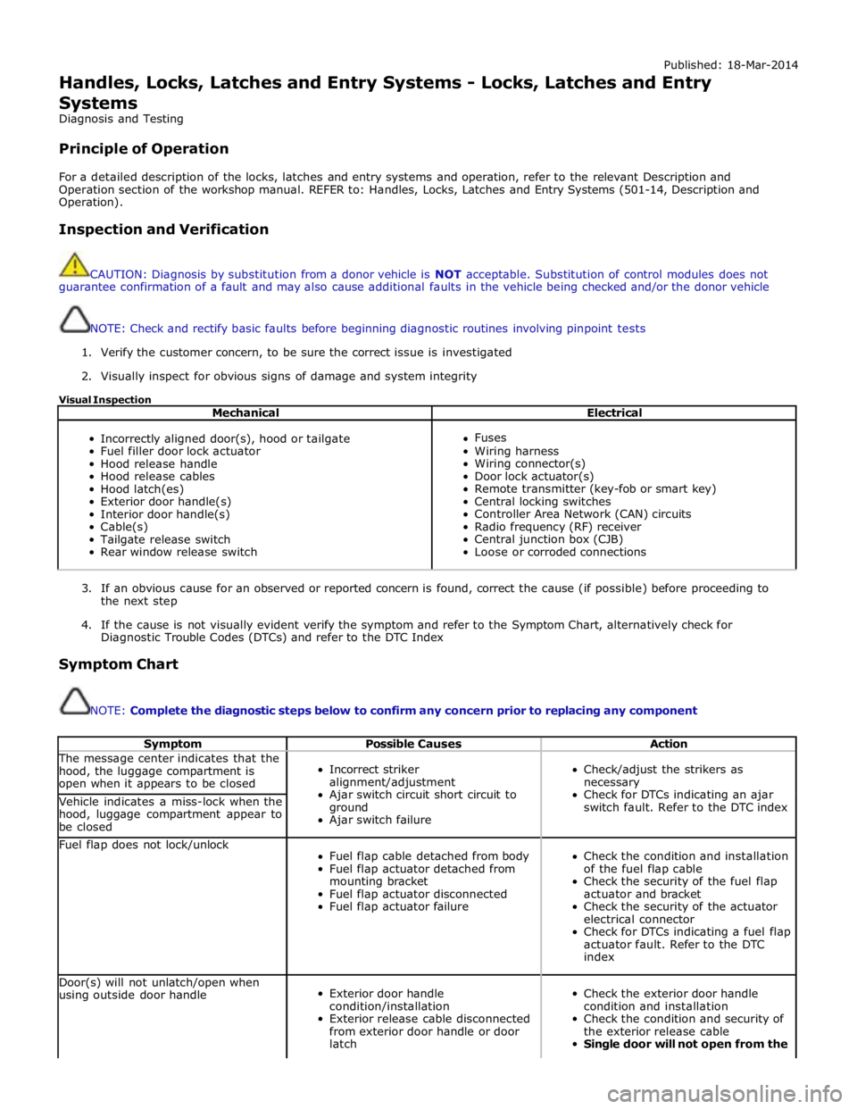
Published: 18-Mar-2014
Handles, Locks, Latches and Entry Systems - Locks, Latches and Entry Systems
Diagnosis and Testing
Principle of Operation
For a detailed description of the locks, latches and entry systems and operation, refer to the relevant Description and
Operation section of the workshop manual. REFER to: Handles, Locks, Latches and Entry Systems (501-14, Description and
Operation).
Inspection and Verification
CAUTION: Diagnosis by substitution from a donor vehicle is NOT acceptable. Substitution of control modules does not
guarantee confirmation of a fault and may also cause additional faults in the vehicle being checked and/or the donor vehicle
NOTE: Check and rectify basic faults before beginning diagnostic routines involving pinpoint tests
1. Verify the customer concern, to be sure the correct issue is investigated
2. Visually inspect for obvious signs of damage and system integrity
Visual Inspection
Mechanical Electrical
Incorrectly aligned door(s), hood or tailgate
Fuel filler door lock actuator
Hood release handle
Hood release cables
Hood latch(es)
Exterior door handle(s)
Interior door handle(s)
Cable(s)
Tailgate release switch
Rear window release switch
Fuses
Wiring harness
Wiring connector(s)
Door lock actuator(s)
Remote transmitter (key-fob or smart key)
Central locking switches
Controller Area Network (CAN) circuits
Radio frequency (RF) receiver
Central junction box (CJB)
Loose or corroded connections
3. If an obvious cause for an observed or reported concern is found, correct the cause (if possible) before proceeding to
the next step
4. If the cause is not visually evident verify the symptom and refer to the Symptom Chart, alternatively check for
Diagnostic Trouble Codes (DTCs) and refer to the DTC Index
Symptom Chart
NOTE: Complete the diagnostic steps below to confirm any concern prior to replacing any component
Symptom Possible Causes Action The message center indicates that the
hood, the luggage compartment is
open when it appears to be closed
Incorrect striker
alignment/adjustment
Ajar switch circuit short circuit to
ground
Ajar switch failure
Check/adjust the strikers as
necessary
Check for DTCs indicating an ajar
switch fault. Refer to the DTC index Vehicle indicates a miss-lock when the
hood, luggage compartment appear to
be closed Fuel flap does not lock/unlock
Fuel flap cable detached from body
Fuel flap actuator detached from
mounting bracket
Fuel flap actuator disconnected
Fuel flap actuator failure
Check the condition and installation
of the fuel flap cable
Check the security of the fuel flap
actuator and bracket
Check the security of the actuator
electrical connector
Check for DTCs indicating a fuel flap
actuator fault. Refer to the DTC
index Door(s) will not unlatch/open when
using outside door handle
Exterior door handle
condition/installation
Exterior release cable disconnected
from exterior door handle or door
latch
Check the exterior door handle
condition and installation
Check the condition and security of
the exterior release cable
Single door will not open from the
Page 2687 of 3039

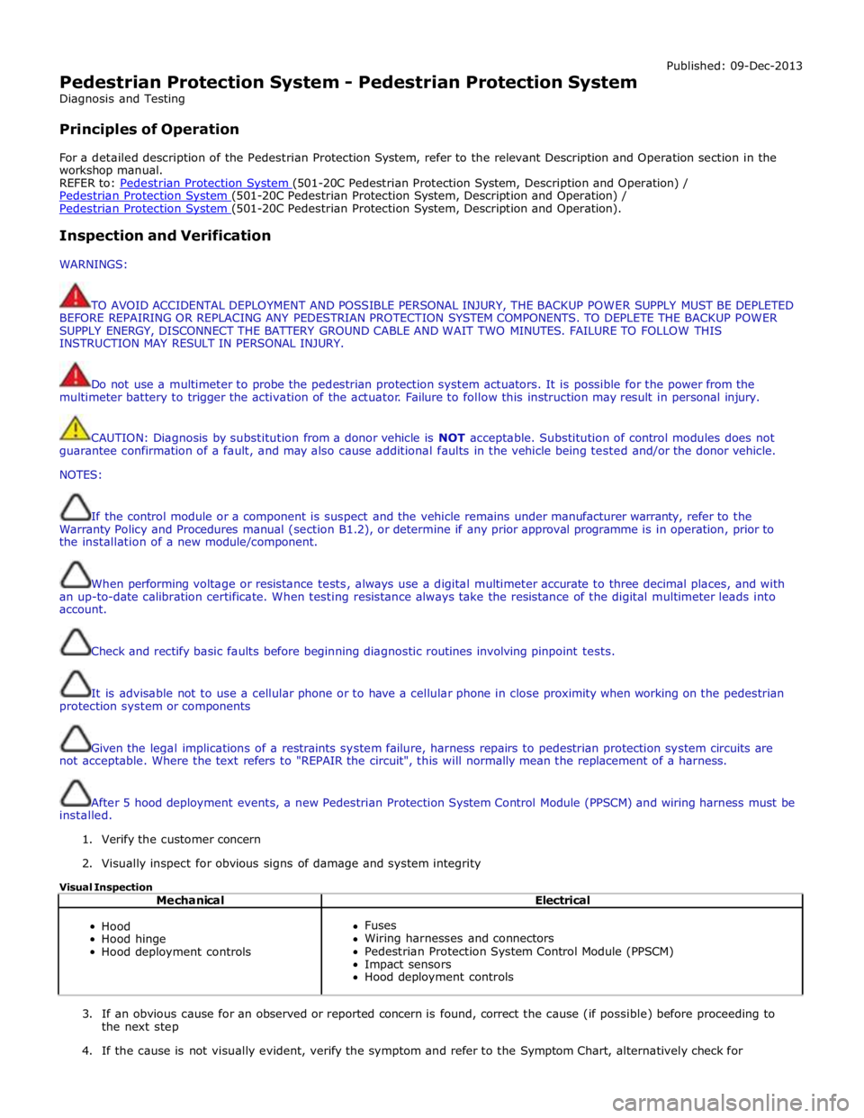
Pedestrian Protection System - Pedestrian Protection System
Diagnosis and Testing
Principles of Operation Published: 09-Dec-2013
For a detailed description of the Pedestrian Protection System, refer to the relevant Description and Operation section in the
workshop manual.
REFER to: Pedestrian Protection System (501-20C Pedestrian Protection System, Description and Operation) / Pedestrian Protection System (501-20C Pedestrian Protection System, Description and Operation) / Pedestrian Protection System (501-20C Pedestrian Protection System, Description and Operation).
Inspection and Verification
WARNINGS:
TO AVOID ACCIDENTAL DEPLOYMENT AND POSSIBLE PERSONAL INJURY, THE BACKUP POWER SUPPLY MUST BE DEPLETED
BEFORE REPAIRING OR REPLACING ANY PEDESTRIAN PROTECTION SYSTEM COMPONENTS. TO DEPLETE THE BACKUP POWER
SUPPLY ENERGY, DISCONNECT THE BATTERY GROUND CABLE AND WAIT TWO MINUTES. FAILURE TO FOLLOW THIS
INSTRUCTION MAY RESULT IN PERSONAL INJURY.
Do not use a multimeter to probe the pedestrian protection system actuators. It is possible for the power from the
multimeter battery to trigger the activation of the actuator. Failure to follow this instruction may result in personal injury.
CAUTION: Diagnosis by substitution from a donor vehicle is NOT acceptable. Substitution of control modules does not
guarantee confirmation of a fault, and may also cause additional faults in the vehicle being tested and/or the donor vehicle.
NOTES:
If the control module or a component is suspect and the vehicle remains under manufacturer warranty, refer to the
Warranty Policy and Procedures manual (section B1.2), or determine if any prior approval programme is in operation, prior to
the installation of a new module/component.
When performing voltage or resistance tests, always use a digital multimeter accurate to three decimal places, and with
an up-to-date calibration certificate. When testing resistance always take the resistance of the digital multimeter leads into
account.
Check and rectify basic faults before beginning diagnostic routines involving pinpoint tests.
It is advisable not to use a cellular phone or to have a cellular phone in close proximity when working on the pedestrian
protection system or components
Given the legal implications of a restraints system failure, harness repairs to pedestrian protection system circuits are
not acceptable. Where the text refers to "REPAIR the circuit", this will normally mean the replacement of a harness.
After 5 hood deployment events, a new Pedestrian Protection System Control Module (PPSCM) and wiring harness must be
installed.
1. Verify the customer concern
2. Visually inspect for obvious signs of damage and system integrity
Visual Inspection
Mechanical Electrical
Hood
Hood hinge
Hood deployment controls
Fuses
Wiring harnesses and connectors
Pedestrian Protection System Control Module (PPSCM)
Impact sensors
Hood deployment controls
3. If an obvious cause for an observed or reported concern is found, correct the cause (if possible) before proceeding to
the next step
4. If the cause is not visually evident, verify the symptom and refer to the Symptom Chart, alternatively check for