2010 JAGUAR XFR climate control
[x] Cancel search: climate controlPage 1111 of 3039

Published: 11-May-2011
Engine Cooling - V8 5.0L Petrol/V8 S/C 5.0L Petrol - Engine Cooling - Overview
Description and Operation
OVERVIEW
The engine cooling system maintains the engine within an optimum temperature range under changing ambient and engine
operating conditions. The system is a pressurized expansion tank system with continuous bleeds to separate air from the
coolant and prevent the formation of air locks. The engine cooling system also provides:
Heating for:
- The passenger compartment. For additional information, refer to 412-01 Climate Control.
- The throttle body.
Cooling for:
- The engine oil cooler. For additional information, refer to 303-01F Engine - 5.0L, Vehicles With: Supercharger or
303-01E Engine - 5.0L, Vehicles Without: Supercharger.
- The transmission fluid cooler. For additional information, refer to 307-02B Transmission/Transaxle Cooling -
5.0L/3.0L Diesel.
The primary components of the engine cooling system are the:
Coolant pump.
Thermostat.
Radiator.
Auxiliary radiator (SC (supercharger) vehicles only).
Cooling fan.
Expansion tank.
Engine oil cooler.
Outlet tube and heater manifold.
Connecting hoses and pipes.
Page 1149 of 3039
Published: 19-Nov-2013
Engine Cooling - V8 5.0L Petrol/V8 S/C 5.0L Petrol - Cooling Module Vehicles
With: Supercharger
Removal and Installation
Removal
NOTE: Removal steps in this procedure may contain installation details.
1. Refer to: Battery Disconnect and Connect (414-01 Battery, Mounting and Cables, General Procedures).
2. Refer to: Air Conditioning (A/C) System Recovery, Evacuation and Charging (412-00 Climate Control System - General Information, General Procedures).
3. WARNING: Make sure to support the vehicle with axle stands.
Raise and support the vehicle.
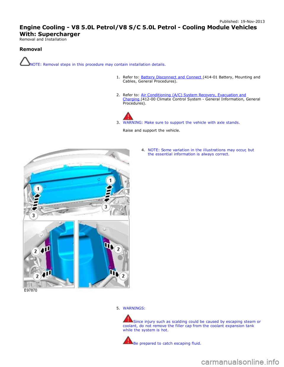
4. NOTE: Some variation in the illustrations may occur, but
the essential information is always correct.
5. WARNINGS:
Since injury such as scalding could be caused by escaping steam or
coolant, do not remove the filler cap from the coolant expansion tank
while the system is hot.
Be prepared to catch escaping fluid.
Page 1535 of 3039
Published: 11-May-2011
Automatic Transmission/Transaxle External Controls - V6 3.0L Petrol -
Transmission Control Switch (TCS)
Removal and Installation
Removal
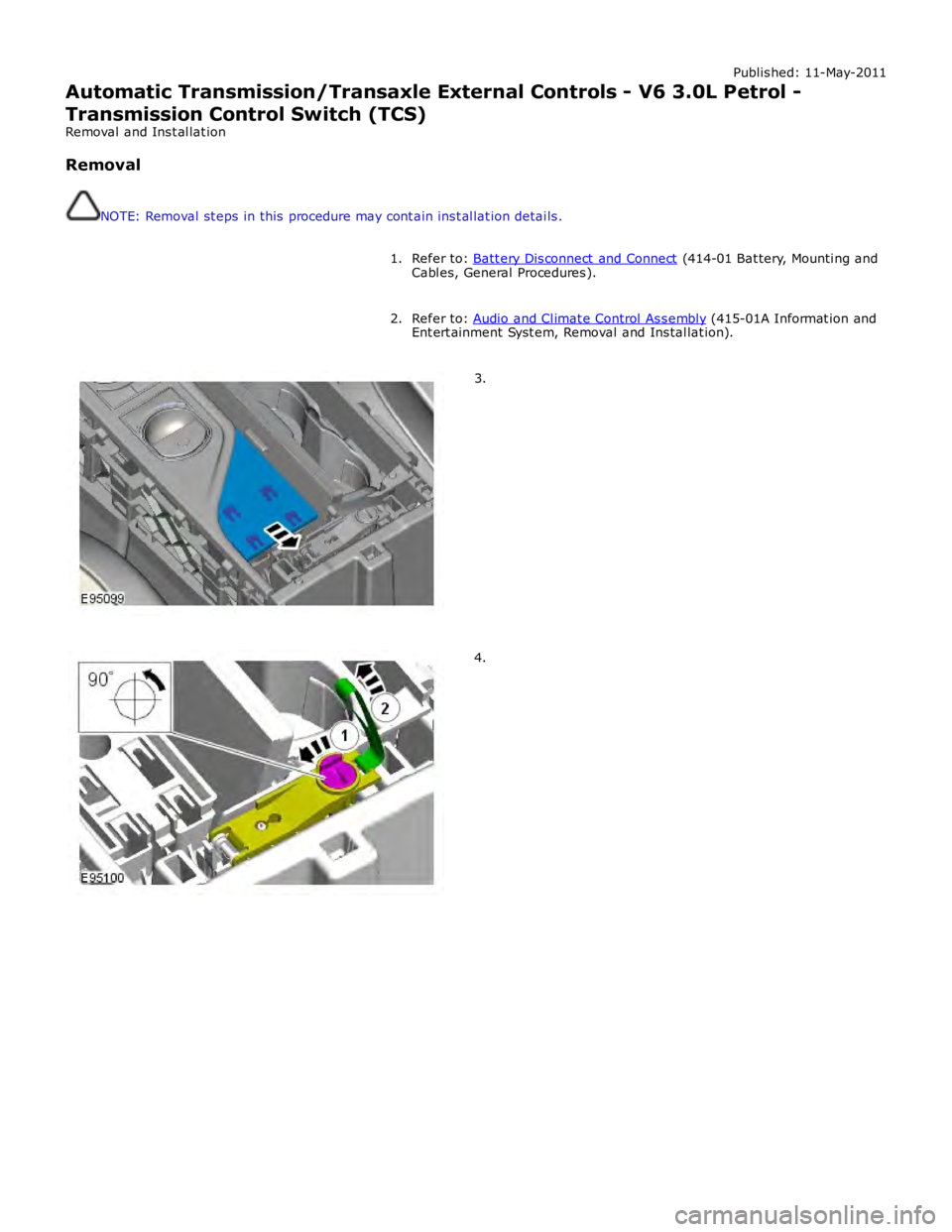
NOTE: Removal steps in this procedure may contain inst allation details.
Refer to: Batt ery Disconnect and Connect (414-01 Battery, Mounting and
Cables, General Procedures). 1.
Refer to: Audio and Climate Control Assembly (415-01A Informat ion and
Entert ainment Syst em, Removal and Installat ion). 2.3.4.
Page 1663 of 3039
Climate Control System - General Information -
Lubricants, Fluids, Sealers and Adhesives
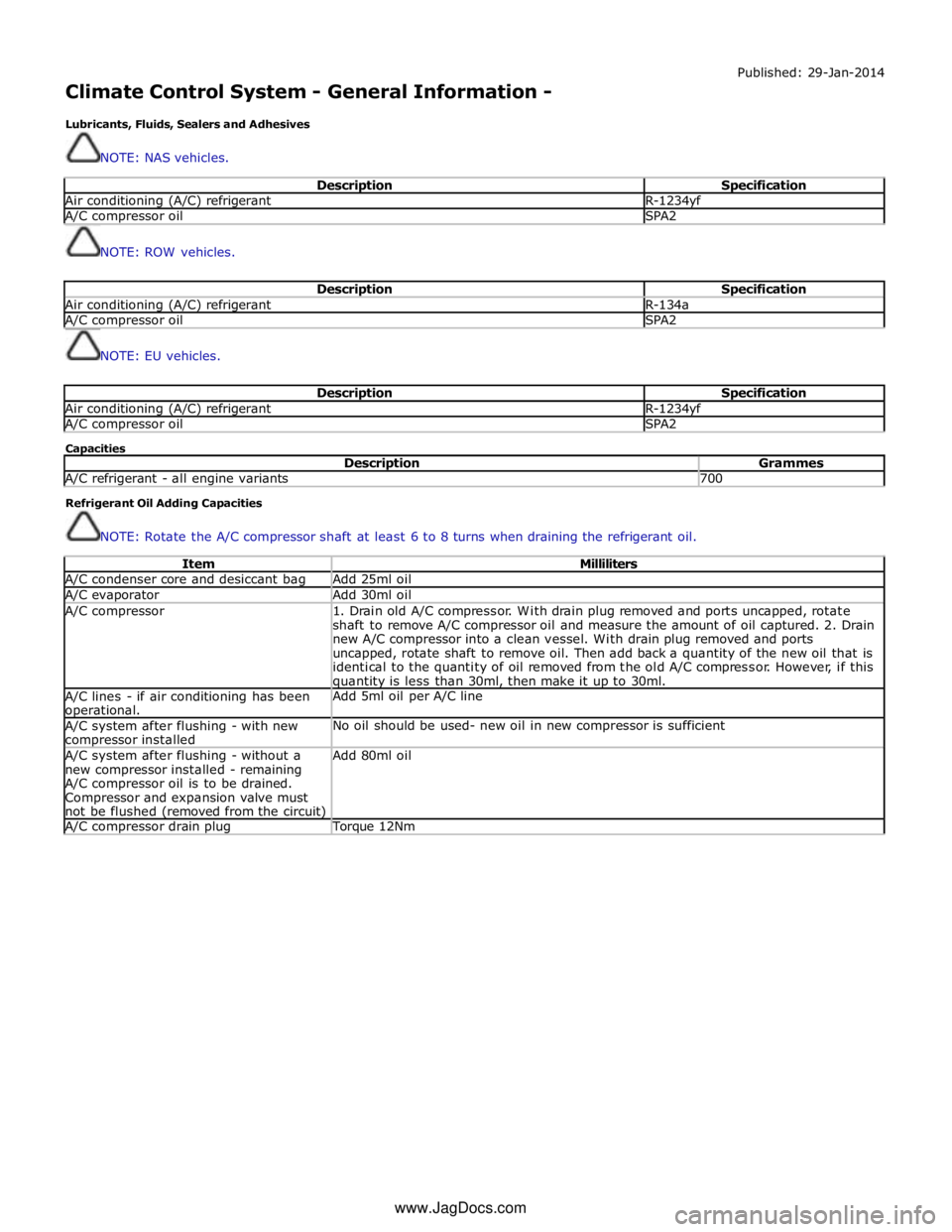
NOTE: NAS vehicles. Published: 29-Jan-2014
Description Specification Air conditioning (A/C) refrigerant R-1234yf A/C compressor oil SPA2
NOTE: ROW vehicles.
Description Specification Air conditioning (A/C) refrigerant R-134a A/C compressor oil SPA2
NOTE: EU vehicles.
Description Specification Air conditioning (A/C) refrigerant R-1234yf A/C compressor oil SPA2 Capacities
Description Grammes A/C refrigerant - all engine variants 700 Refrigerant Oil Adding Capacities
NOTE: Rotate the A/C compressor shaft at least 6 to 8 turns when draining the refrigerant oil.
Item Milliliters A/C condenser core and desiccant bag Add 25ml oil A/C evaporator Add 30ml oil A/C compressor
1. Drain old A/C compressor. With drain plug removed and ports uncapped, rotate
shaft to remove A/C compressor oil and measure the amount of oil captured. 2. Drain
new A/C compressor into a clean vessel. With drain plug removed and ports
uncapped, rotate shaft to remove oil. Then add back a quantity of the new oil that is
identical to the quantity of oil removed from the old A/C compressor. However, if this quantity is less than 30ml, then make it up to 30ml. A/C lines - if air conditioning has been operational. Add 5ml oil per A/C line A/C system after flushing - with new compressor installed No oil should be used- new oil in new compressor is sufficient A/C system after flushing - without a
new compressor installed - remaining
A/C compressor oil is to be drained.
Compressor and expansion valve must
not be flushed (removed from the circuit) Add 80ml oil A/C compressor drain plug Torque 12Nm www.JagDocs.com
Page 1664 of 3039
Published: 11-Jul-2014
Climate Control System - General Information - Climate Control System
Diagnosis and Testing
Principles of Operation
For a detailed description of the Climate Control System, refer to the relevant Description and Operation sections in the
Workshop Manual. REFER to:
Air Distribution and Filtering (412-01 Climate Control, Description and Operation), Air Distribution and Filtering (412-01 Climate Control, Description and Operation), Air Distribution and Filtering (412-01 Climate Control, Description and Operation), Heating and Ventilation (412-01 Climate Control, Description and Operation), Heating and Ventilation (412-01 Climate Control, Description and Operation), Heating and Ventilation (412-01 Climate Control, Description and Operation), Air Conditioning (412-01 Climate Control, Description and Operation), Air Conditioning (412-01 Climate Control, Description and Operation), Air Conditioning (412-01 Climate Control, Description and Operation), Control Components (412-01 Climate Control, Description and Operation), Control Components (412-01 Climate Control, Description and Operation), Control Components (412-01 Climate Control, Description and Operation), Electric Booster Heater (412-02 Auxiliary Climate Control, Description and Operation), Electric Booster Heater (412-02 Auxiliary Climate Control, Description and Operation), Electric Booster Heater (412-02 Auxiliary Climate Control, Description and Operation).
Inspection and Verification
WARNING: Servicing must be carried out by personnel familiar with both vehicle system and the charging and testing
equipment. All operations must be carried out in a well ventilated area away from open flame and heat sources.
CAUTION: Diagnosis by substitution from a donor vehicle is NOT acceptable. Substitution of control modules does not
guarantee confirmation of a fault, and may also cause additional faults in the vehicle being tested and/or the donor vehicle.
NOTE: Check and rectify basic faults before beginning diagnostic routines involving pinpoint tests.
1. Verify the customer concern
2. Visually inspect for obvious signs of damage and system integrity
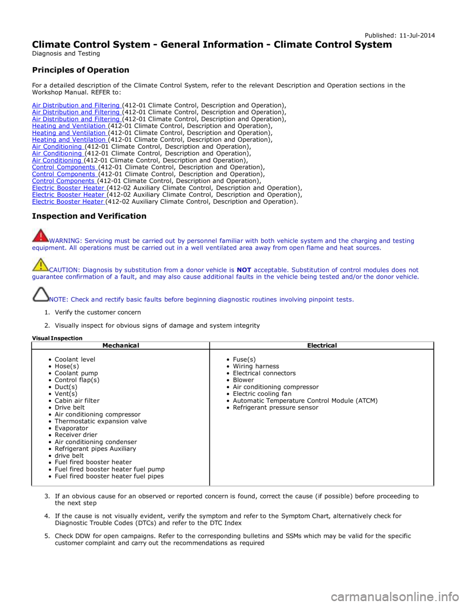
Visual Inspection
Mechanical Electrical
Coolant level
Hose(s)
Coolant pump
Control flap(s)
Duct(s)
Vent(s)
Cabin air filter
Drive belt
Air conditioning compressor
Thermostatic expansion valve
Evaporator
Receiver drier
Air conditioning condenser
Refrigerant pipes Auxiliary
drive belt
Fuel fired booster heater
Fuel fired booster heater fuel pump
Fuel fired booster heater fuel pipes
Fuse(s)
Wiring harness
Electrical connectors
Blower
Air conditioning compressor
Electric cooling fan
Automatic Temperature Control Module (ATCM)
Refrigerant pressure sensor
3. If an obvious cause for an observed or reported concern is found, correct the cause (if possible) before proceeding to
the next step
4. If the cause is not visually evident, verify the symptom and refer to the Symptom Chart, alternatively check for
Diagnostic Trouble Codes (DTCs) and refer to the DTC Index
5. Check DDW for open campaigns. Refer to the corresponding bulletins and SSMs which may be valid for the specific
customer complaint and carry out the recommendations as required
Page 1667 of 3039
1 Check the pressure values Are the pressure gauge readings too high? Yes
GO to C7. No
Test inconclusive. GO to Pinpoint Test B. C7: GAUGE TEST 7
NOTE: This test is performed with the engine not running. 1 Stop the engine 2 Refer to the relevant section of the workshop manual and recover the refrigerant Was the weight of the recovered refrigerant more than specified for the air conditioning system? Yes
Refer to the relevant section of the workshop manual and evacuate and recharge the air conditioning
system. GO to Pinpoint Test B. No
Install a new thermal expansion valve. Refer to the relevant section of the workshop manual and
evacuate and recharge the air conditioning system. GO to Pinpoint Test B.
PINPOINT TEST D : NITROGEN LEAK TESTS TEST
CONDITIONS DETAILS/RESULTS/ACTIONS D1: NITROGEN LEAK TEST
CAUTION: When charging the system with nitrogen, the pressure should be regulated to 7.0 bar.
NOTE: This test is performed with the engine not running. 1 Charge the air conditioning system with nitrogen 2 Isolate the nitrogen supply 3 Monitor the pressure gauge and check for leaks Has the source of the leak been identified?
Yes
Rectify the leak as necessary. Install a new receiver drier. Refer to the relevant section of the workshop
manual and evacuate and recharge the air conditioning system. GO to Pinpoint Test B. No
Refer to the relevant section of the workshop manual and evacuate and recharge the air conditioning system. GO to Pinpoint Test B.
DTC Index
For a list of Diagnostic Trouble Codes (DTCs) that could be logged on this vehicle, please refer to Section 100-00.
REFER to: Diagnostic Trouble Code (DTC) Index - DTC: Climate Control Module (HVAC) (100-00 General Information, Description and Operation).
Page 1668 of 3039
Published: 11-May-2011
Climate Control System - General Information - Air Conditioning (A/C) System
Recovery, Evacuation and Charging
General Procedures
1. WARNING: Servicing must be carried out by personnel familliar with both
vehicle system and the charging and testing equipment. All operations
must be carried out in a well ventilated area away from open flame and
heat sources.
NOTE: The receiver drier need only be changed under the following
circumstances: There is dirt in the refrigerant circuit ( eg. compressor
seizure ), the system is leaking and refrigerant has been lost to
atmosphere, or the refrigerant circuit has been open more than 24 hours,
due to repair.
Refrigerant recovery.
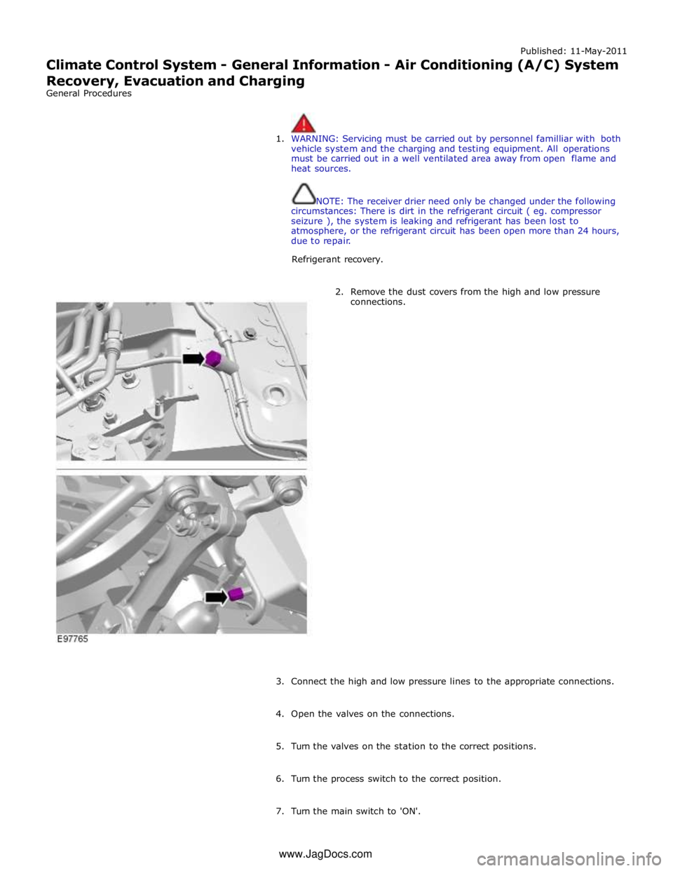
2. Remove the dust covers from the high and low pressure
connections.
3. Connect the high and low pressure lines to the appropriate connections.
4. Open the valves on the connections.
5. Turn the valves on the station to the correct positions.
6. Turn the process switch to the correct position.
7. Turn the main switch to 'ON'. www.JagDocs.com
Page 1671 of 3039
Published: 11-May-2011
Climate Control System - General Information - Air Conditioning (A/C) System
Flushing
General Procedures
1. WARNINGS:
Use extreme care and observe all safety precautions related to the
use of refrigerants. Due to refrigerant hazards, always wear safety
goggles and non-penetrable gloves when working on or flushing air
conditioning (A/C) systems. Failure to follow this instruction may result
in personal injury.
When flushing the A/C system, refer to the manufacturers
equipment instructions for additional information. Failure to do so may
result in system damage or personal injury.
The A/C refrigerant analyzer must be used before the recovery of
any vehicle's A/C refrigerant. Failure to do so puts shop bulk refrigerant
at risk of contamination. If the vehicle A/C refrigerant is contaminated,
refer the customer to return to the repair facility that performed the last
A/C repair. If the customer wishes to pay the additional cost, use the
A/C recovery equipment that is designated for recovering contaminated
A/C refrigerant. All contaminated A/C refrigerant must be disposed of as
hazardous waste. For additional information, refer to the manufacturers
equipment instructions. Failure to follow this instruction may result in
personal injury.
Prior to using the A/C flushing equipment for the first time, follow
the operating instructions. Failure to follow this instruction may result in
personal injury.
CAUTION: Prior to flushing, remove and discard the desiccant sack.
Depending on the equipment used, other A/C components may have to
be removed prior to flushing. For additional information, refer to the
manufacturers equipment instructions before flushing the A/C system.
Recover the refrigerant.
For additional information, refer to Air conditioning (A/C) System Recovery, Evacuation and Charging in this section.
2. Remove the desiccant sack.
For additional information, refer to Section 412-03 Air Conditioning.
3. Flush the system. For additional information, refer to the manufacturers
equipment instructions.
4. Install new refrigerant lines if blocked with debris.
5. Install a new desiccant sack.
For additional information, refer to Section 412-03 Air Conditioning.
6. Add the required amount of oil to the A/C system depending on the
repair procedure.
For additional information, refer to Refrigerant Oil Adding in this section.
7. Evacuate and charge the A/C system.
For additional information, refer to Air conditioning (A/C) System Recovery, Evacuation and Charging in this section.
8. Carry out fluorescent dye leak detection test.