2010 JAGUAR XFR wheel torque
[x] Cancel search: wheel torquePage 483 of 3039

7 Rear accelerometer 8 Instrument cluster 9 JaguarDrive selector module 10 ABS (anti-lock brake system) module 11 TCM (transmission control module) 12 ECM (engine control module) 13 RH (right-hand) rear damper 14 RH front damper 15 LH (left-hand) front damper 16 LH rear damper 17 LH rear suspension height sensor 18 RH rear suspension height sensor 19 LH front suspension height sensor 20 RH front accelerometer 21 RH front suspension height sensor 22 Adaptive damping module 23 LH front accelerometer
PRINCIPLES OF OPERATION System Operation
The adaptive damping module uses a combination of information from other system modules and data from the accelerometers
and suspension height sensors to measure the vehicle and suspension states and driver inputs. Using this information, the
adaptive damping module applies algorithms to control the dampers for the current driving conditions.
The adaptive damping module receives signals on the high speed CAN bus from the following system components: Brake Pressure - ABS module. Brake Pressure Quality Factor - ABS module. Car Configuration Parameters - AJB. Center Differential Range Actual - ECM. Engine Speed - ECM. Engine Speed Quality Factor - ECM. Engine Torque Flywheel Actual - ECM. Engine Torque Flywheel Actual Quality Factor - ECM. Gear Position Target - TCM. Lateral Acceleration - ABS module. Power Mode (Ignition Signal) - CJB. Power Mode Quality Factor - CJB. Roll Stability Control Mode - ABS module. Steering Wheel Angle - ABS module. Steering Wheel Angle Speed - ABS module. Steering Wheel Angle Status - ABS module. Terrain Mode Requested - JaguarDrive selector.
Torque Converter Slip - TCM. Vehicle Information Parameters HS - AJB Vehicle Speed - ABS module. Vehicle Speed Quality Factor - ABS module. Front Left Wheel Speed - ABS module. Front Left Wheel Speed Quality Factor - ABS module. Front Right Wheel Speed - ABS module. Front Right Wheel Speed Quality Factor - ABS module. Rear Left Wheel Speed - ABS module. Rear Left Wheel Speed Quality Factor - ABS module. Rear Right Wheel Speed Quality Factor - ABS module. Rear Right Wheel Speed - ABS module. The adaptive damping module also outputs information on the high speed CAN bus for use by other systems as follows: Fault Message - instrument cluster.
Terrain Mode Change Status - JaguarDrive selector.
Terrain Mode - JaguarDrive selector.
The adaptive damping module monitors the input signals and operates the damper solenoids. The input signals are used in
control modes and a force required for each damper for that mode is calculated. An arbitration mode monitors the force
requirements from each mode and apportions a force to a damper. The force is converted to the appropriate current and sent to
the damper.
The control modes are as follows:
Page 495 of 3039

Published: 11-May-2011
Ride and Handling Optimization - Ride and Handling Optimization - System
Operation and Component Description
Description and Operation
JAGUARDRIVE CONTROL OPERATION
Engine Management System System Operation
The Engine Management System (EMS) varies the accelerator pedal maps to change the amount of torque per percentage of
pedal travel. The EMS can also change the accelerator pedal response to control the allowed torque change relative to the
speed of pedal travel.
Each driving mode uses a combination of operating parameters for each sub-system. Changing between driving modes initiates
a different set of operating characteristics, which will be noticeable to the driver. The driver will notice differences in engine
response when, for example, the accelerator pedal is held in a constant position and the driving mode is changed from Winter
to Dynamic, the driver will notice the torque and engine speed increase. Similarly, if the mode is changed from Normal or
Dynamic to Winter the driver will notice a reduction in torque and engine speed.
NOTE: The change in torque and engine speed can take approximately 30 seconds and care must be taken not to confuse
the JaguarDrive Control system operation with an EMS fault.
Transmission Control
The TCM (transmission control module) changes the shift maps for the JaguarDrive Control mode selected. This changes the
shift points providing early or late upshifts and downshifts. For example, on slippery surfaces in Winter mode the transmission
will select 2nd gear for starting from a standstill on a flat surface to minimize wheel slip.
Anti-lock Braking System Control
The ABS (anti-lock brake system) module controls several vehicle functions and adjusts the operating parameters of these
functions to optimize the selected JaguarDrive Control mode. Traction control uses different slip/acceleration thresholds to
improve traction and vehicle composure. For example, the system sensitivity is increased on slippery surfaces to reduce wheel
spin.
If TracDSC is selected or DSC is switched off, then subsequently the JaguarDrive Control mode is changed, DSC is automatically
switched back on (or to TracDSC for Dynamic mode).
The stability control uses different threshold values for the selected mode, reducing the requirement for the driver to change
the DSC system mode for optimum performance in various driving scenarios.
Incorrect Mode Usage
Selection of an inappropriate mode is discouraged in the following ways:
The active mode icon is continually displayed in the instrument cluster message center
In any special mode, when the ignition has been in the off position continuously for more than 6 hours, the JaguarDrive
Control system defaults to the special modes off (DSC on).
Selection of an inappropriate mode for the conditions will not endanger the driver or immediately cause damage to the vehicle.
Continued use of an inappropriate mode may reduce the life of some components. The driver may notice a different vehicle
response, with the engine and transmission responses being different than in the special modes off.
Driver Information
The instrument cluster contains a message center, which displays vehicle information to the driver. The message center
contains the JaguarDrive Control mode icons, which display the currently selected mode. If no symbol is displayed, no special
mode is selected and the system is in special modes off.
Any required changes to the subsystems are also passed to the driver in the form of warning illumination in the instrument
cluster or appropriate messages in the message center, DSC off for example.
In Dynamic mode when the transmission is in manual mode, the gear information is displayed in amber when the appropriate
engine speed is reached for optimum sporty change point.
DIAGNOSTICS
JaguarDrive Control relies on the correct functionality of the sub-systems. If one of the sub-systems develops a fault, the
JaguarDrive Control system will not function, even though the fault is not in the JaguarDrive Control system.
The JaguarDrive Selector module and rotary control should only be investigated if there are no apparent faults in any of the
sub-systems. If a fault in a sub-system is subsequently corrected, the JaguarDrive Control system will function normally after
an ignition on and off cycle.
Page 532 of 3039

6 Oil temperature sensor 7 High speed CAN from suspension control module 8 CJB (central junction box)
System Operation
ELECTRONIC
DIFFERENTIAL
-
5.0L
SUPERCHARGER
VEHICLES
FROM
2010MY
The
multi-plate
clutch
prevents
excessive
differential
slip and
therefore
maximizes
the
traction
performance
of
the
vehicle.
This
is
fundamentally
different
from
'braked'
traction
control
systems,
which
can
only
counteract
differential
slip when it
occurs.
A
certain
amount
of
differential
slip is
required
to
allow
the
vehicle
to
turn
corners
and
to
remain
stable
under
control
of
the
ABS
(anti-lock
brake
system).
The
system
is
completely
automatic and
does
not
require
any
special
driver
input.
The
multi-plate
clutch
actively
controls
the
torque
flow
through
the
differential
and
optimizes
the
torque
distribution in
the
driveline.
The
clutch
biases
the
torque
from
the
differential
to
the
wheel
with the
higher
grip
and prevents
the
wheel
with the
lower
grip
from
spinning.
www.JagDocs.com
Page 536 of 3039

60 Oil seal The multi-plate clutch is contained in a clutch basket attached to the differential carrier with the crown wheel securing bolts.
Alternate plates of the clutch pack are keyed to the clutch basket and the LH sun gear. A pressure disc is installed on the outer end of the clutch pack and keyed to the clutch basket. A thrust race on the end of the clutch basket incorporates lugs which
extend through the clutch basket onto the pressure disc.
The actuator assembly is mounted on bearings on the outboard end of the clutch basket, against the thrust race. The actuator
assembly consists of input and output actuators separated by five ball bearings. A locking pin in the cover engages with a slot
in the output actuator to prevent it turning, but allow it to move axially. The input actuator engages with the reduction gearbox
and is free to rotate relative to the cover. Ball bearings locate in curved grooves in the mating faces of the input and
output actuators. The bottom surface of each groove incorporates a ramp. Rotation of the input actuator forces the ball
bearings up the ramps in the grooves and induces an axial movement in the output actuator. The thrust race and pressure disc
transfer the axial movement from the output actuator to the clutch pack.
Item Description 1 Actuator 2 Multi-plate clutch 3 Differential The motor is a 12 V dc motor that adjusts the frictional loading of the multi-plate clutch, via the reduction gearbox and the
actuator assembly, under the control of the DLM. Adjusting the frictional loading of the multi-plate clutch adjusts the locking
torque between the crown wheel drive gear and the sun wheel.
Four bolts attach the motor to the reduction gearbox, which is located in position on the cover with two dowels, and secured
with four bolts. An O-ring seals the joint between the motor and the reduction gearbox.
The motor is driven by a 12 V dc feed direct from the DLM. The motor also incorporates the following connections with the
DLM:
A motor temperature sensor, to prevent excessive use from damaging the motor.
Two Hall effect motor position sensors, to enable closed loop control of the motor.
The temperature sensor provides a differential oil temperature signal to the DLM, to prevent excessive use from damaging the
multi-plate clutch.
Differential Locking Module (DLM)
The DLM controls operation of the electronic differential. The DLM is attached to a bracket located on the LH side of the luggage compartment, immediately forward of the fender tail lamp, behind the trim.
Page 537 of 3039

bus allows the DLM to communicate with other systems on the vehicle.
A certain amount of differential slip is required to allow the vehicle to turn corners and to remain stable under control of the
ABS. The ADM monitors the driver's demands through primary vehicle controls and automatically sets the slip torque in the differential. The system is completely automatic and does not require any special driver input.
The differential strategy in the ADM includes:
A pre-loading function, increasing locking torque with increased driving torque.
A slip controller to decrease locking torque for optimum comfort, e.g. parking.
The ADM memorizes the position of the motor when the ignition is switched off.
CAN bus messages used by the ADM include wheel speed, steering angle, automatic transmission speed, temperature information, car configuration, axle ratios and mode inputs.
The ADM also sends messages via the CAN bus to tell other control modules on the network the status of the electronic differential. The clutch torque and default mode status are some of the main signals sent out by the ADM.
If the DLM or ADM are replaced, a Jaguar approved diagnostic system must be connected to the vehicle and the differential
self-calibration procedure must be performed. This procedure must also be performed if the motor or electronic differential is
replaced.
If a fault occurs with the electronic differential, the ADM, the DLM, or one of the required input signals, the ADM records an
error code and displays a warning in the message center.
The following messages can be displayed:
Message Description Chime E-DIFF NOT
AVAILABLE Differential temperature has reached the overheat threshold. System deactivated until temperature
returns within limits. Single E-DIFF FAULT Fault has occurred with electronic differential. System deactivated until fault rectified. Single
Page 571 of 3039

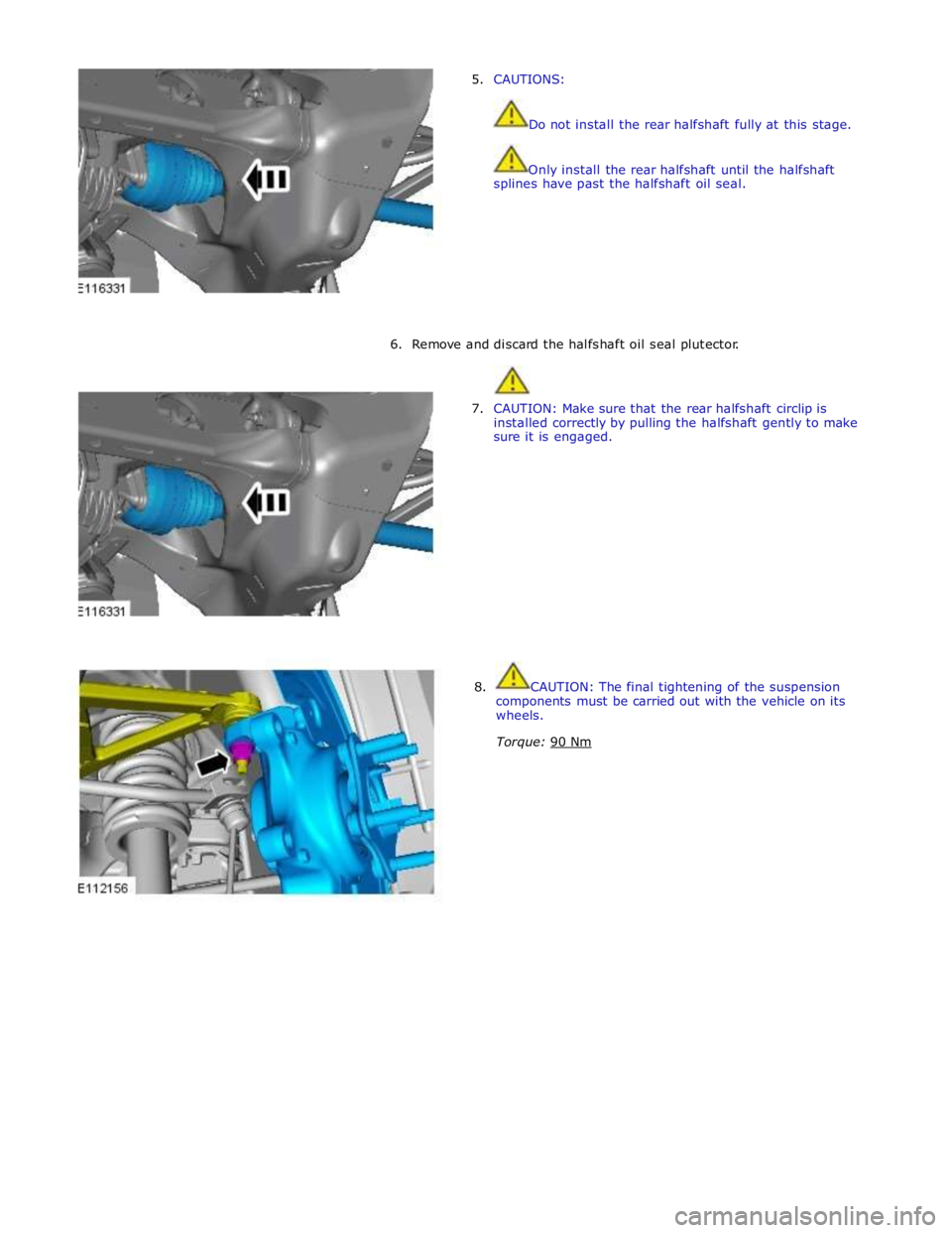
5. CAUTIONS:
Do not install the rear halfshaft fully at this stage.
Only install the rear halfshaft until the halfshaft
splines have past the halfshaft oil seal.
6. Remove and discard the halfshaft oil seal plutector.
7. CAUTION: Make sure that the rear halfshaft circlip is
installed correctly by pulling the halfshaft gently to make
sure it is engaged.
8. CAUTION: The final tightening of the suspension
components must be carried out with the vehicle on its
wheels.
Torque: 90 Nm
Page 572 of 3039

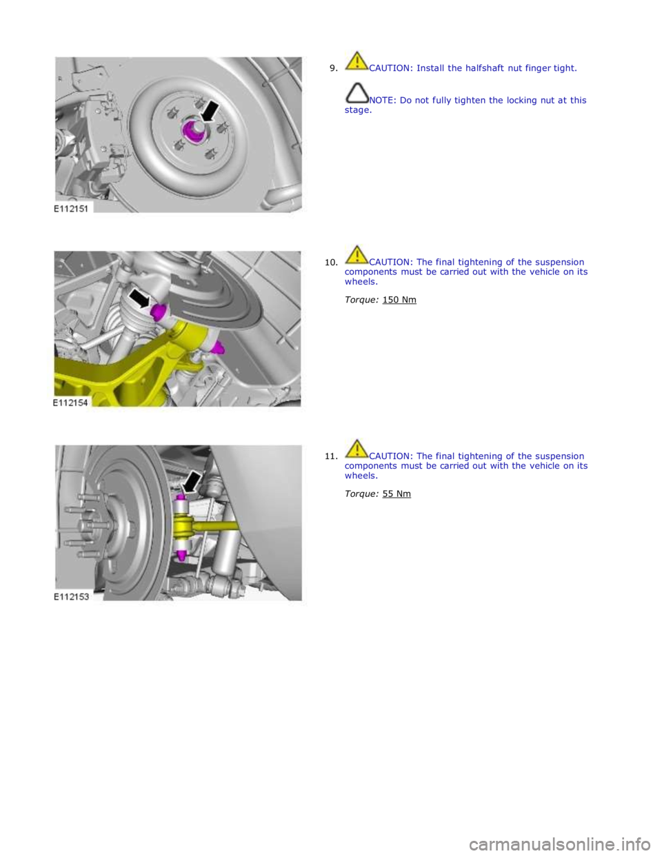
9.
10.
11. CAUTION: Install the halfshaft nut finger tight.
NOTE: Do not fully tighten the locking nut at this
stage.
CAUTION: The final tightening of the suspension
components must be carried out with the vehicle on its
wheels.
Torque: 150 Nm
CAUTION: The final tightening of the suspension
components must be carried out with the vehicle on its
wheels.
Torque: 55 Nm
Page 574 of 3039

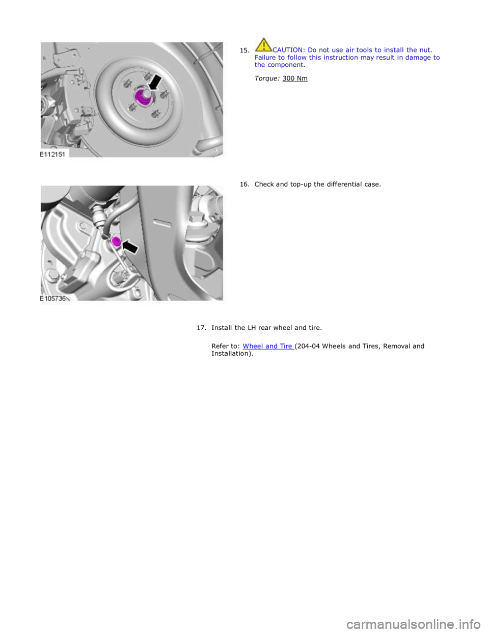
15.
16. CAUTION: Do not use air tools to install the nut.
Failure to follow this instruction may result in damage to
the component.
Torque: 300 Nm
Check and top-up the differential case.
17.
Install the LH rear wheel and tire.
Refer to: Wheel and Tire (204-04 Wheels and Tires, Removal and Installation).