2010 JAGUAR XFR traction control
[x] Cancel search: traction controlPage 1422 of 3039
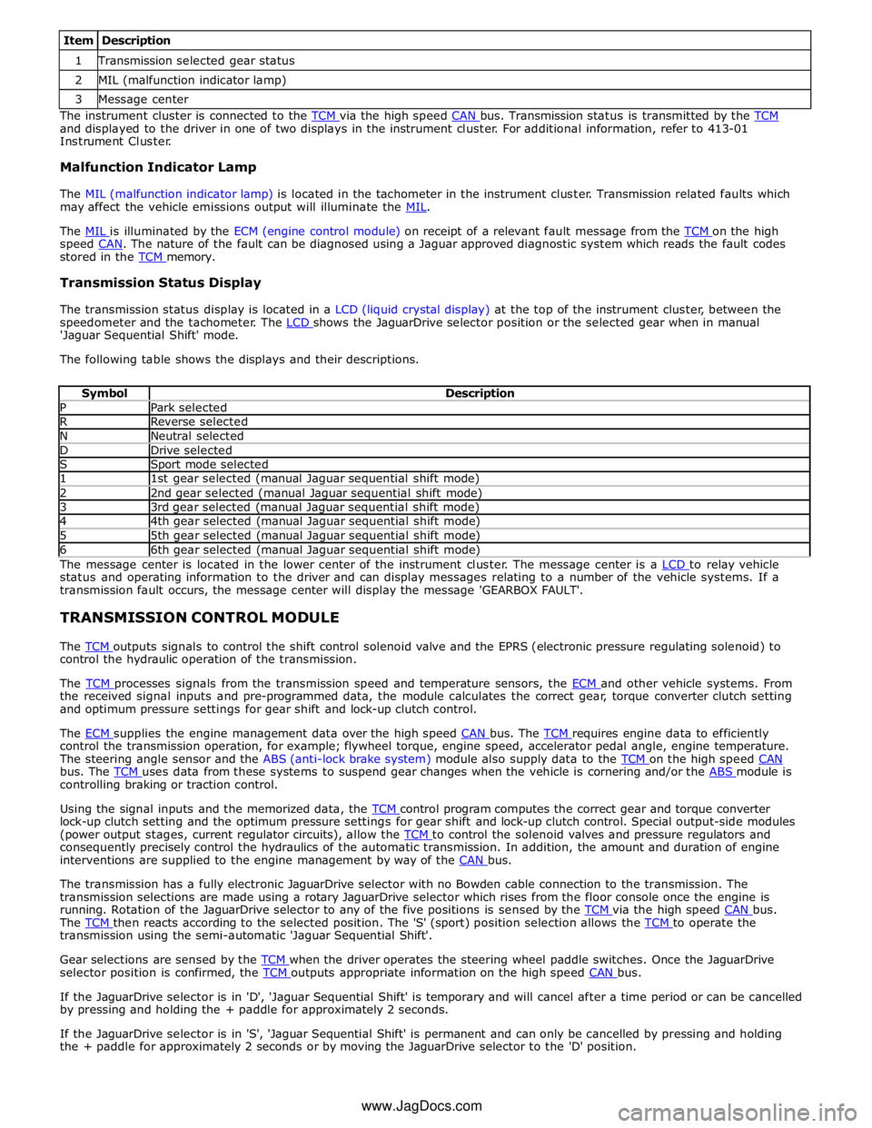
1 Transmission selected gear status 2 MIL (malfunction indicator lamp) 3 Message center The instrument cluster is connected to the TCM via the high speed CAN bus. Transmission status is transmitted by the TCM and displayed to the driver in one of two displays in the instrument cluster. For additional information, refer to 413-01
Instrument Cluster.
Malfunction Indicator Lamp
The MIL (malfunction indicator lamp) is located in the tachometer in the instrument cluster. Transmission related faults which
may affect the vehicle emissions output will illuminate the MIL.
The MIL is illuminated by the ECM (engine control module) on receipt of a relevant fault message from the TCM on the high speed CAN. The nature of the fault can be diagnosed using a Jaguar approved diagnostic system which reads the fault codes stored in the TCM memory.
Transmission Status Display
The transmission status display is located in a LCD (liquid crystal display) at the top of the instrument cluster, between the
speedometer and the tachometer. The LCD shows the JaguarDrive selector position or the selected gear when in manual 'Jaguar Sequential Shift' mode.
The following table shows the displays and their descriptions.
Symbol Description P Park selected R Reverse selected N Neutral selected D Drive selected S Sport mode selected 1 1st gear selected (manual Jaguar sequential shift mode) 2 2nd gear selected (manual Jaguar sequential shift mode) 3 3rd gear selected (manual Jaguar sequential shift mode) 4 4th gear selected (manual Jaguar sequential shift mode) 5 5th gear selected (manual Jaguar sequential shift mode) 6 6th gear selected (manual Jaguar sequential shift mode) The message center is located in the lower center of the instrument cluster. The message center is a LCD to relay vehicle status and operating information to the driver and can display messages relating to a number of the vehicle systems. If a
transmission fault occurs, the message center will display the message 'GEARBOX FAULT'.
TRANSMISSION CONTROL MODULE
The TCM outputs signals to control the shift control solenoid valve and the EPRS (electronic pressure regulating solenoid) to control the hydraulic operation of the transmission.
The TCM processes signals from the transmission speed and temperature sensors, the ECM and other vehicle systems. From the received signal inputs and pre-programmed data, the module calculates the correct gear, torque converter clutch setting
and optimum pressure settings for gear shift and lock-up clutch control.
The ECM supplies the engine management data over the high speed CAN bus. The TCM requires engine data to efficiently control the transmission operation, for example; flywheel torque, engine speed, accelerator pedal angle, engine temperature.
The steering angle sensor and the ABS (anti-lock brake system) module also supply data to the TCM on the high speed CAN bus. The TCM uses data from these systems to suspend gear changes when the vehicle is cornering and/or the ABS module is controlling braking or traction control.
Using the signal inputs and the memorized data, the TCM control program computes the correct gear and torque converter lock-up clutch setting and the optimum pressure settings for gear shift and lock-up clutch control. Special output-side modules
(power output stages, current regulator circuits), allow the TCM to control the solenoid valves and pressure regulators and consequently precisely control the hydraulics of the automatic transmission. In addition, the amount and duration of engine
interventions are supplied to the engine management by way of the CAN bus.
The transmission has a fully electronic JaguarDrive selector with no Bowden cable connection to the transmission. The
transmission selections are made using a rotary JaguarDrive selector which rises from the floor console once the engine is
running. Rotation of the JaguarDrive selector to any of the five positions is sensed by the TCM via the high speed CAN bus. The TCM then reacts according to the selected position. The 'S' (sport) position selection allows the TCM to operate the transmission using the semi-automatic 'Jaguar Sequential Shift'.
Gear selections are sensed by the TCM when the driver operates the steering wheel paddle switches. Once the JaguarDrive selector position is confirmed, the TCM outputs appropriate information on the high speed CAN bus.
If the JaguarDrive selector is in 'D', 'Jaguar Sequential Shift' is temporary and will cancel after a time period or can be cancelled
by pressing and holding the + paddle for approximately 2 seconds.
If the JaguarDrive selector is in 'S', 'Jaguar Sequential Shift' is permanent and can only be cancelled by pressing and holding
the + paddle for approximately 2 seconds or by moving the JaguarDrive selector to the 'D' position.
www.JagDocs.com
Page 1597 of 3039
Symptom Possible Causes Action Electronic engine control
Throttle motor
Restricted accelerator pedal
travel (carpet, etc)
Ignition system
Transmission malfunction Check for air leakage in air intake system
Ensure accelerator pedal is free from restriction
Check for electronic engine controls, ignition, engine
emission system and transmission related DTCs and
refer to the relevant DTC Index Engine backfires
Fuel pump/lines
Air leakage
Electronic engine controls
Ignition system
Sticking variable camshaft
timing (VCT) hub
Check for fuel system failures
Check for air leakage in intake air system
Check for electronic engine controls, ignition system
and VCT system related DTCs and refer to the
relevant DTC Index Engine surges
Fuel pump/lines
Electronic engine controls
Throttle motor
Ignition system
Check for fuel system failures
Check for electronic engine controls, throttle system
and ignition system related DTCs and refer to the
relevant DTC Index Engine detonates/knocks
Fuel pump/lines
Air leakage
Electronic engine controls
Sticking VCT hub
Check for fuel system failures
Check for air leakage in intake air system
Check for electronic engine controls and VCT system
related DTCs and refer to the relevant DTC Index No throttle response
Electronic engine controls
Throttle motor
Check for electronic engine controls and throttle
system related DTCs and refer to the relevant DTC
Index Poor throttle response
Breather system
disconnected/restricted
Electronic engine controls
Transmission malfunction
Traction control event
Air leakage
Ensure the engine breather system is free from
restriction and is correctly installed
Check for electronic engine controls, transmission
and traction control related DTCs and refer to the
related DTC Index
Check for air leakage in intake air system Fuel gauge reading empty
with fuel in the fuel tank
Active fuel level sensor
circuit open circuit
Passive fuel level sensor
circuit open circuit
Instrument cluster internal
failure
Using the manufacturer approved diagnostic system,
perform the guided diagnostic routine - Fuel Level
Sensor Test Fuel gauge not reading empty
with no fuel in the fuel tank
Jet pump fault
Fuel crossover tube blocked
or leaking
Using the manufacturer approved diagnostic system,
check datalogger signals - Fuel Sender 2 (0x61B8) -
Fuel Sender 1 (0x61B7). Refer to the table below. If
the right sensor reads empty when the left sensor
reads more than empty, check that the jet pump is
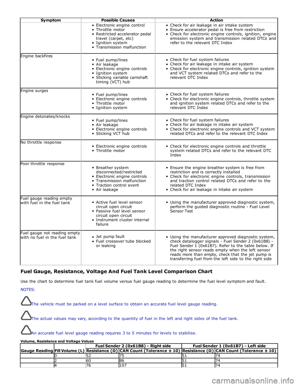
transferring fuel from the left side to the right side Fuel Gauge, Resistance, Voltage And Fuel Tank Level Comparison Chart
Use the chart to determine fuel tank fuel volume versus fuel gauge reading to determine the fuel level symptom and fault.
NOTES:
The vehicle must be parked on a level surface to obtain an accurate fuel level gauge reading.
The actual values may vary, according to the quantity of fuel in the left and right sides of the fuel tank.
An accurate fuel level gauge reading requires 3 to 5 minutes for levels to stabilise.
Volume, Resistance and Voltage Values
Gauge Reading
Fill Volume (L) Fuel Sender 2 (0x61B8) - Right side Fuel Sender 1 (0x61B7) - Left side Resistance (Ω) CAN Count (Tolerance ± 10) Resistance (Ω) CAN Count (Tolerance ± 10) 0 52 75 51 74 2 60 86 51 74 4 76 107 51 74
Page 1786 of 3039
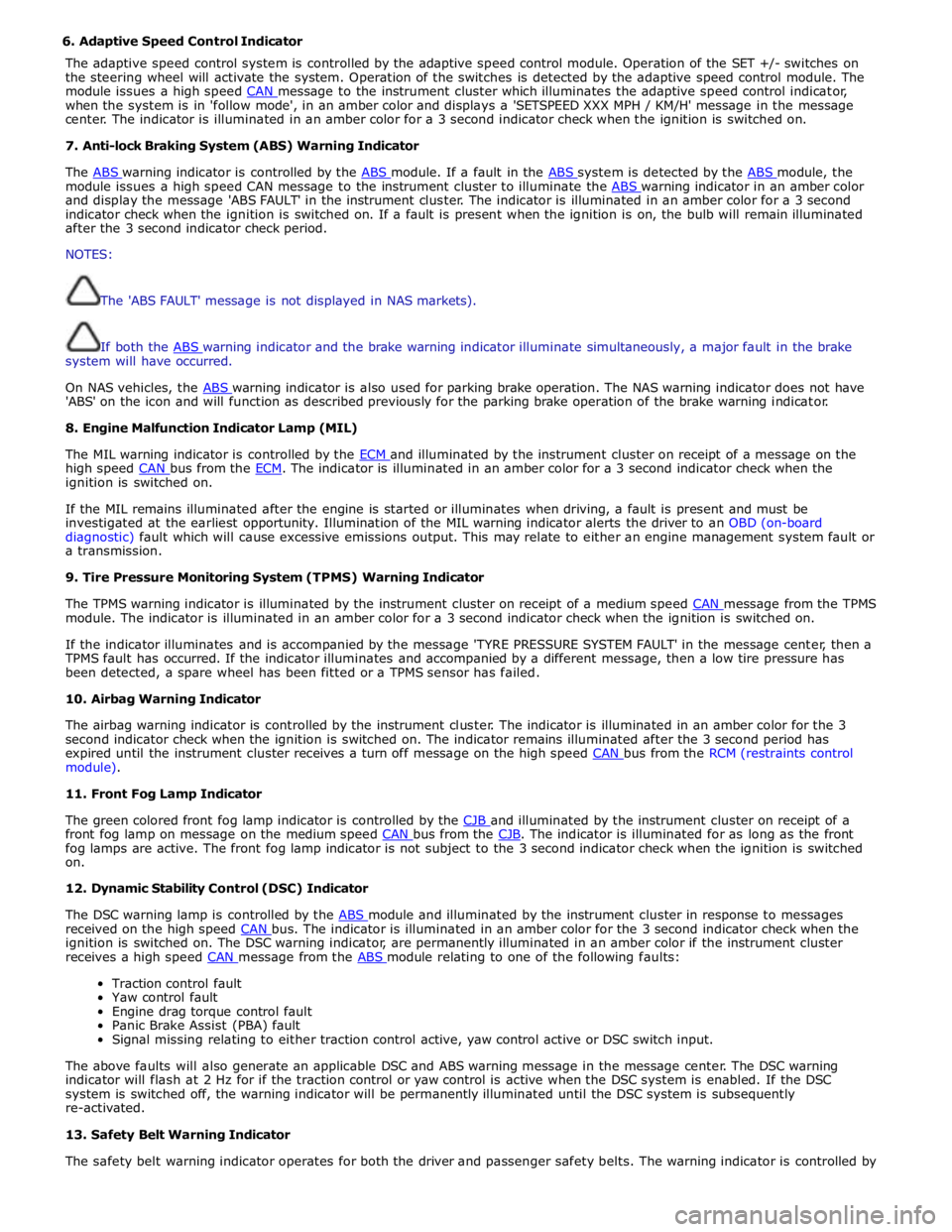
6. Adaptive Speed Control Indicator
The adaptive speed control system is controlled by the adaptive speed control module. Operation of the SET +/- switches on
the steering wheel will activate the system. Operation of the switches is detected by the adaptive speed control module. The
module issues a high speed CAN message to the instrument cluster which illuminates the adaptive speed control indicator, when the system is in 'follow mode', in an amber color and displays a 'SETSPEED XXX MPH / KM/H' message in the message
center. The indicator is illuminated in an amber color for a 3 second indicator check when the ignition is switched on.
7. Anti-lock Braking System (ABS) Warning Indicator
The ABS warning indicator is controlled by the ABS module. If a fault in the ABS system is detected by the ABS module, the module issues a high speed CAN message to the instrument cluster to illuminate the ABS warning indicator in an amber color and display the message 'ABS FAULT' in the instrument cluster. The indicator is illuminated in an amber color for a 3 second
indicator check when the ignition is switched on. If a fault is present when the ignition is on, the bulb will remain illuminated
after the 3 second indicator check period.
NOTES:
The 'ABS FAULT' message is not displayed in NAS markets).
If both the ABS warning indicator and the brake warning indicator illuminate simultaneously, a major fault in the brake system will have occurred.
On NAS vehicles, the ABS warning indicator is also used for parking brake operation. The NAS warning indicator does not have 'ABS' on the icon and will function as described previously for the parking brake operation of the brake warning indicator.
8. Engine Malfunction Indicator Lamp (MIL)
The MIL warning indicator is controlled by the ECM and illuminated by the instrument cluster on receipt of a message on the high speed CAN bus from the ECM. The indicator is illuminated in an amber color for a 3 second indicator check when the ignition is switched on.
If the MIL remains illuminated after the engine is started or illuminates when driving, a fault is present and must be
investigated at the earliest opportunity. Illumination of the MIL warning indicator alerts the driver to an OBD (on-board
diagnostic) fault which will cause excessive emissions output. This may relate to either an engine management system fault or
a transmission.
9. Tire Pressure Monitoring System (TPMS) Warning Indicator
The TPMS warning indicator is illuminated by the instrument cluster on receipt of a medium speed CAN message from the TPMS module. The indicator is illuminated in an amber color for a 3 second indicator check when the ignition is switched on.
If the indicator illuminates and is accompanied by the message 'TYRE PRESSURE SYSTEM FAULT' in the message center, then a
TPMS fault has occurred. If the indicator illuminates and accompanied by a different message, then a low tire pressure has
been detected, a spare wheel has been fitted or a TPMS sensor has failed.
10. Airbag Warning Indicator
The airbag warning indicator is controlled by the instrument cluster. The indicator is illuminated in an amber color for the 3
second indicator check when the ignition is switched on. The indicator remains illuminated after the 3 second period has
expired until the instrument cluster receives a turn off message on the high speed CAN bus from the RCM (restraints control module).
11. Front Fog Lamp Indicator
The green colored front fog lamp indicator is controlled by the CJB and illuminated by the instrument cluster on receipt of a front fog lamp on message on the medium speed CAN bus from the CJB. The indicator is illuminated for as long as the front fog lamps are active. The front fog lamp indicator is not subject to the 3 second indicator check when the ignition is switched
on.
12. Dynamic Stability Control (DSC) Indicator
The DSC warning lamp is controlled by the ABS module and illuminated by the instrument cluster in response to messages received on the high speed CAN bus. The indicator is illuminated in an amber color for the 3 second indicator check when the ignition is switched on. The DSC warning indicator, are permanently illuminated in an amber color if the instrument cluster
receives a high speed CAN message from the ABS module relating to one of the following faults:
Traction control fault
Yaw control fault
Engine drag torque control fault
Panic Brake Assist (PBA) fault
Signal missing relating to either traction control active, yaw control active or DSC switch input.
The above faults will also generate an applicable DSC and ABS warning message in the message center. The DSC warning
indicator will flash at 2 Hz for if the traction control or yaw control is active when the DSC system is enabled. If the DSC
system is switched off, the warning indicator will be permanently illuminated until the DSC system is subsequently
re-activated.
13. Safety Belt Warning Indicator
The safety belt warning indicator operates for both the driver and passenger safety belts. The warning indicator is controlled by
Page 1796 of 3039

ETM Test/no. Message Center Display Gauge/Indicator/Display
Tested.
Range
Description 25:XXX -
XXXX
26:XXX -
XXXX
27.XXX -
XXXX 25 - Passenger seat belt
26 - Not used
27 - On-board temp ref 18 - Analogue
Inputs.
ANALOG
INPUTS.
#: RAW -
Ratio
28:XXX -
XXXX
29:XXX -
XXXX
30:XXX -
XXXX
31.XXX -
XXXX Cluster inputs. TDB.
Displays Hex coding of inputs 28 -
31.
28 - On-board temp
29 - Not used
30 - Not used
31 - Not used 19 -
Speedometer. SPEEDOMETER.
RAW:
MPH:
KMH:
DRIVER: Speedometer inputs. .
Displays present .
Speedometer inputs values;
Speedometer will indicate
present road speed. 20 -
Tachometer. TACHOMETER.
RAW:
ACTUAL:
DRIVER: Tachometer inputs. .
Displays present received
Tachometer input values,
tachometer will indicate present
engine RPM. 21 - Fuel
system. FUEL SYSTEM.
(A) (B)
RAW: X X
FILT: X X
PERCENT: X X Fuel indication system. .
Displays present received fuel level
A/D inputs in decimal, fuel gauge
will indicate present filtered level. 22 - Battery
voltage. BATTERY VOLTAGE.
LOCAL:
VEHICLE:
RAW:
A/D: Battery voltage. .
Displays present received battery
input voltage values. If message not
received or invalid display will be '_
_ _'. 23 - Rolling
counts. ROLLING COUNTS.
ODO:
FUEL: Odometer and fuel gauge. 0 - 255.
Displays present received odometer
and fuel level input values in
decimal, value is a rolling count. If
either message not received or
invalid respective display will be ' _
_ _' . 24 - VAPS. VAPS.
CURRENT:
COMMAND:
STATUS: Variable assistance power
steering (VAPS) status. .
CURRENT is displayed in mA.
COMMAND is last command sent to
VAPS chip. STATUS is last status
returned from VAPS chip. 25 - Module MODULE STATUS. Provides status of; Ignition
CONNECTED
Communication (Coms) ok status. (IGN), Dynamic Stability Control IGN
(DSC), Adaptive Cruise Control WAITING Coms not received, not an DSC
(ACC) and Adaptive damping MISSING issue ACC
control module (ADCM) modules. FAULTY. Coms never received ADCM Coms error . 26 - Module MODULE STATUS. Provides status of; Electronic
CONNECTED
Communication (Coms) ok status. park brake (EPB), Pedestrian EPB
Impact ECU (PIE), Restraints WAITING Coms not received, not an PIE
control module (RCM) and MISSING issue RCM
Traction control module (TCM), FAULTY. Coms never received TCM
modules.. Coms error . 27 - Module
status. MODULE STATUS.
ECM
RCC Provides status of; Engine
control module (ECM), Rear
Climate Control (RCC), Driver
Door Control (DDC) and
CONNECTED
WAITING
MISSING
Communication (Coms) ok
Coms not received, not an
issue
Page 1869 of 3039
5. EQUIPMENT
All equipment used must be functionally capable of meeting the compliance requirements. Please refer to the approved
equipment document (JLR 000015).
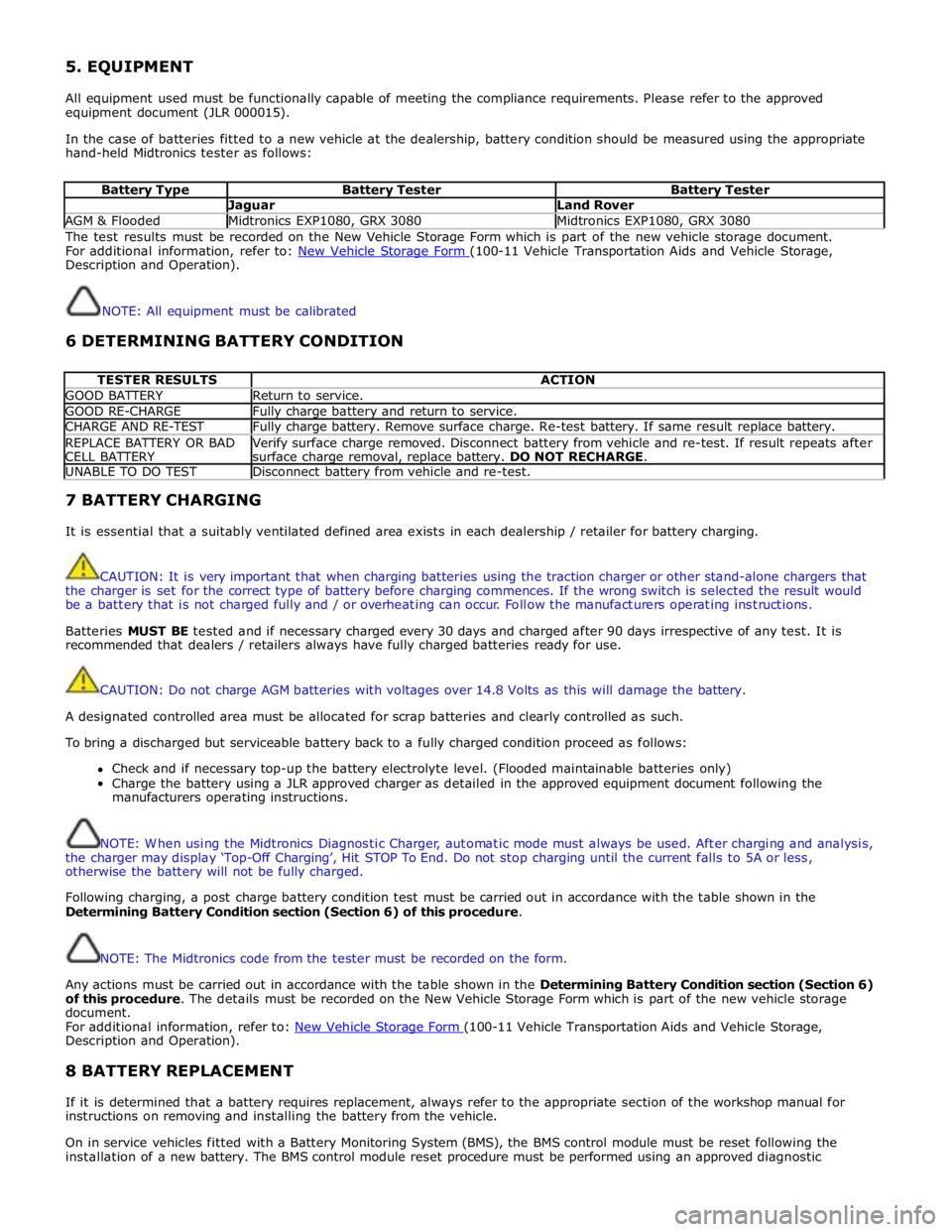
In the case of batteries fitted to a new vehicle at the dealership, battery condition should be measured using the appropriate
hand-held Midtronics tester as follows:
Battery Type Battery Tester Battery Tester Jaguar Land Rover AGM & Flooded Midtronics EXP1080, GRX 3080 Midtronics EXP1080, GRX 3080 The test results must be recorded on the New Vehicle Storage Form which is part of the new vehicle storage document.
For additional information, refer to: New Vehicle Storage Form (100-11 Vehicle Transportation Aids and Vehicle Storage, Description and Operation).
NOTE: All equipment must be calibrated
6 DETERMINING BATTERY CONDITION
TESTER RESULTS ACTION GOOD BATTERY Return to service. GOOD RE-CHARGE Fully charge battery and return to service. CHARGE AND RE-TEST Fully charge battery. Remove surface charge. Re-test battery. If same result replace battery. REPLACE BATTERY OR BAD
CELL BATTERY Verify surface charge removed. Disconnect battery from vehicle and re-test. If result repeats after
surface charge removal, replace battery. DO NOT RECHARGE. UNABLE TO DO TEST Disconnect battery from vehicle and re-test. 7 BATTERY CHARGING
It is essential that a suitably ventilated defined area exists in each dealership / retailer for battery charging.
CAUTION: It is very important that when charging batteries using the traction charger or other stand-alone chargers that
the charger is set for the correct type of battery before charging commences. If the wrong switch is selected the result would
be a battery that is not charged fully and / or overheating can occur. Follow the manufacturers operating instructions.
Batteries MUST BE tested and if necessary charged every 30 days and charged after 90 days irrespective of any test. It is
recommended that dealers / retailers always have fully charged batteries ready for use.
CAUTION: Do not charge AGM batteries with voltages over 14.8 Volts as this will damage the battery.
A designated controlled area must be allocated for scrap batteries and clearly controlled as such.
To bring a discharged but serviceable battery back to a fully charged condition proceed as follows:
Check and if necessary top-up the battery electrolyte level. (Flooded maintainable batteries only)
Charge the battery using a JLR approved charger as detailed in the approved equipment document following the
manufacturers operating instructions.
NOTE: When using the Midtronics Diagnostic Charger, automatic mode must always be used. After charging and analysis,
the charger may display ‘Top-Off Charging’, Hit STOP To End. Do not stop charging until the current falls to 5A or less,
otherwise the battery will not be fully charged.
Following charging, a post charge battery condition test must be carried out in accordance with the table shown in the
Determining Battery Condition section (Section 6) of this procedure.
NOTE: The Midtronics code from the tester must be recorded on the form.
Any actions must be carried out in accordance with the table shown in the Determining Battery Condition section (Section 6)
of this procedure. The details must be recorded on the New Vehicle Storage Form which is part of the new vehicle storage
document.
For additional information, refer to: New Vehicle Storage Form (100-11 Vehicle Transportation Aids and Vehicle Storage, Description and Operation).
8 BATTERY REPLACEMENT
If it is determined that a battery requires replacement, always refer to the appropriate section of the workshop manual for
instructions on removing and installing the battery from the vehicle.
On in service vehicles fitted with a Battery Monitoring System (BMS), the BMS control module must be reset following the
installation of a new battery. The BMS control module reset procedure must be performed using an approved diagnostic
Page 2596 of 3039
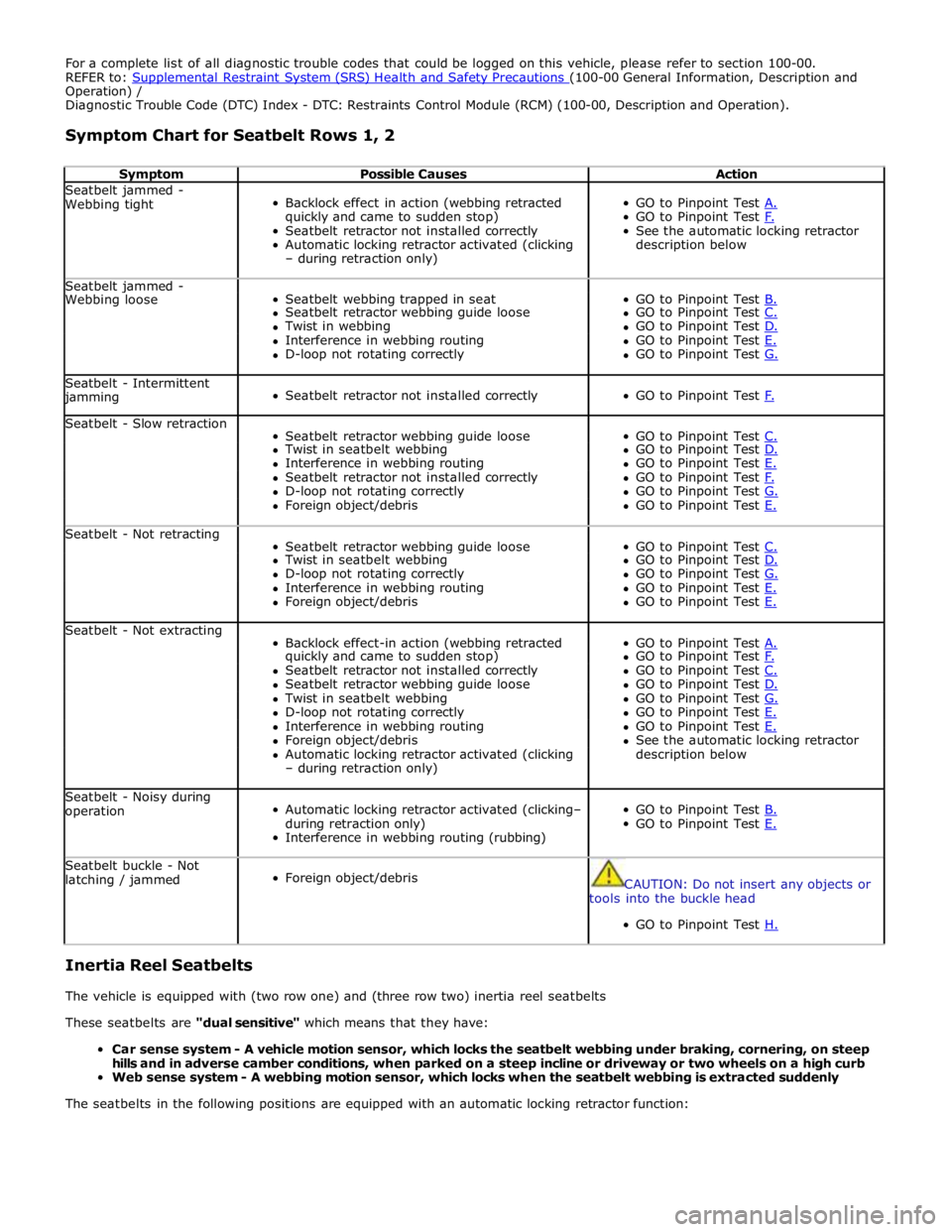
For a complete list of all diagnostic trouble codes that could be logged on this vehicle, please refer to section 100-00.
REFER to: Supplemental Restraint System (SRS) Health and Safety Precautions (100-00 General Information, Description and Operation) /
Diagnostic Trouble Code (DTC) Index - DTC: Restraints Control Module (RCM) (100-00, Description and Operation).
Symptom Chart for Seatbelt Rows 1, 2
Symptom Possible Causes Action Seatbelt jammed -
Webbing tight
Backlock effect in action (webbing retracted
quickly and came to sudden stop)
Seatbelt retractor not installed correctly
Automatic locking retractor activated (clicking
– during retraction only)
GO to Pinpoint Test A. GO to Pinpoint Test F. See the automatic locking retractor
description below Seatbelt jammed -
Seatbelt webbing trapped in seat
GO to Pinpoint Test B. Webbing loose Seatbelt retractor webbing guide loose GO to Pinpoint Test C. Twist in webbing GO to Pinpoint Test D. Interference in webbing routing GO to Pinpoint Test E. D-loop not rotating correctly GO to Pinpoint Test G. Seatbelt - Intermittent jamming
Seatbelt retractor not installed correctly
GO to Pinpoint Test F. Seatbelt - Slow retraction
Seatbelt retractor webbing guide loose
GO to Pinpoint Test C. Twist in seatbelt webbing GO to Pinpoint Test D. Interference in webbing routing GO to Pinpoint Test E. Seatbelt retractor not installed correctly GO to Pinpoint Test F. D-loop not rotating correctly GO to Pinpoint Test G. Foreign object/debris GO to Pinpoint Test E. Seatbelt - Not retracting
Seatbelt retractor webbing guide loose
GO to Pinpoint Test C. Twist in seatbelt webbing GO to Pinpoint Test D. D-loop not rotating correctly GO to Pinpoint Test G. Interference in webbing routing GO to Pinpoint Test E. Foreign object/debris GO to Pinpoint Test E. Seatbelt - Not extracting
Backlock effect-in action (webbing retracted
GO to Pinpoint Test A. quickly and came to sudden stop) GO to Pinpoint Test F. Seatbelt retractor not installed correctly GO to Pinpoint Test C. Seatbelt retractor webbing guide loose GO to Pinpoint Test D. Twist in seatbelt webbing GO to Pinpoint Test G. D-loop not rotating correctly GO to Pinpoint Test E. Interference in webbing routing GO to Pinpoint Test E. Foreign object/debris See the automatic locking retractor Automatic locking retractor activated (clicking description below – during retraction only) Seatbelt - Noisy during
operation
Automatic locking retractor activated (clicking–
during retraction only)
Interference in webbing routing (rubbing)
GO to Pinpoint Test B. GO to Pinpoint Test E. Seatbelt buckle - Not
latching / jammed
Foreign object/debris
CAUTION: Do not insert any objects or
tools into the buckle head
GO to Pinpoint Test H.
Inertia Reel Seatbelts
The vehicle is equipped with (two row one) and (three row two) inertia reel seatbelts
These seatbelts are "dual sensitive" which means that they have:
Car sense system - A vehicle motion sensor, which locks the seatbelt webbing under braking, cornering, on steep
hills and in adverse camber conditions, when parked on a steep incline or driveway or two wheels on a high curb
Web sense system - A webbing motion sensor, which locks when the seatbelt webbing is extracted suddenly
The seatbelts in the following positions are equipped with an automatic locking retractor function: