2010 JAGUAR XFR lights
[x] Cancel search: lightsPage 2055 of 3039
Interior Lighting - Interior Lighting - Overview
Description and Operation
OVERVIEW Published: 11-May-2011
Interior lighting is provided to enable the safe entry and departure from the vehicle for the driver and passengers in low
ambient light conditions, without any manual switching of the lights.
NOTE: The term interior lamps also includes the door mirror approach lamps.
The interior lamps are controlled by the CJB (central junction box) and the RJB (rear junction box) and have 2 modes of
operation: manual and automatic. The front interior lamps in the front overhead console are operated using the 'JaguarSense'
system. The system uses capacitive proximity sensor technology for the switch operation which is integral with the overhead
console. The rear overhead console interior lamps have conventional switches.
In the manual mode the interior lamps can be switched on and off with the JaguarSense system. Positioning your hand
adjacent to each lamp in the front overhead console will switch interior lamps on or off and completely disable the interior
lamp system. In the automatic mode the interior lamp functionality is controlled by the CJB and the RJB and reacts to the vehicle being locked or unlocked and opening the vehicle doors.
In manual mode the interior lamps can be operated by placing your finger(s) close to, or touch, the surface of the appropriate
lamp. The courtesy light and map reading lamps can be operated manually by the 'JaguarSense' system. When in automatic
mode, the courtesy lamp functionality is also controlled by the CJB and the RJB and reacts to the vehicle being locked or unlocked and opening the vehicle doors. To deactivate or activate automatic illumination, touch the front courtesy lamp for
approximately 2 seconds
The driver's and passenger door approach lamps are controlled by the driver's door module and the passenger door module
respectively and operate with the automatic mode. The door modules receive a power supply from the RJB and receive information to illuminate the approach lamps on the medium speed CAN (controller area network) bus from the RJB and the CJB. www.JagDocs.com
Page 2066 of 3039
Published: 11-May-2011
Daytime Running Lamps (DRL) - Daytime Running Lamps (DRL) - System
Operation and Component Description
Description and Operation
CENTRAL JUNCTION BOX (CJB) System Operation
The CJB (central junction box) controls the operation of the DRL (daytime running lamps). The DRL are activated once the CJB detects an ignition on power mode 6 signal.
The CJB also monitors the lighting control switch and the auto lamps feature and overrides the DRL if required.
DAYTIME RUNNING LAMPS - CANADA Component Description
The DRL for this market use full intensity low beam headlamps. The side marker lamps, tail lamps and license plate lamps will be on, but instrument cluster illumination will be off. DRL are active when the following parameters are met:
PARK is not selected on the electronic transmission selector
Electronic Parking Brake (EPB) is off
Power mode 6 (ignition on) detected by the CJB The CJB receives an engine running signal The lighting control switch is in the off or side lamps position.
NOTES:
If the lighting control switch is moved to the headlamp position, DRL are deactivated and normal side lamp and headlamp functionality is operational.
When DRL are active, the headlamp flash function using the left hand steering column multifunction switch will operate normally.
The high beam headlamp function using the left hand steering column stalk switch will be deactivated. When the transmission
is in PARK, DRL are turned off. This is to reduce battery discharge during long periods of engine idling in cold climate conditions. When the electronic transmission selector is moved from the PARK position, normal DRL functionality is restored.
DAYTIME RUNNING LAMPS - DENMARK, HOLLAND, NORWAY, SWEDEN, FINLAND AND POLAND
NOTE: DRL for Poland is on vehicles from 2008MY.
DRL for these markets use full intensity low beam headlamps. Side lamps and license plate lamps will be on, but instrument cluster illumination will be off. DRL are active when the following parameters are met:
Power mode 6 (ignition on) detected by the CJB The CJB receives an engine running signal The lighting control switch is in the off position.
NOTE: When DRL are active, the headlamp flash function using the left hand steering column multifunction switch will operate normally. The high beam headlamp function using the left hand steering column stalk switch will be deactivated.
If the lighting control switch is moved to the side lamp or headlamp positions, DRL are deactivated and normal side lamp and headlamp functionality is operational.
AUTOMATIC HEADLAMPS
On vehicles fitted with the automatic headlamps feature, DRL are overridden if the lighting control switch is in the 'Auto' position and the CJB receives a signal from the rain/light sensor to activate the exterior lights.
When the CJB receives a signal to de-activate the automatic headlamps feature the DRL function is restored providing the parameters for DRL activation are met.
Page 2292 of 3039
Rear View Mirrors - Rear View Mirrors - Overview
Description and Operation
Overview
The exterior mirrors incorporate the following:
Blind spot monitoring indicator
Auto dimming function
Turn signal indicators
Approach lamps
Exterior temperature sensor
Heated mirror function
Reverse dipping function Published: 11-May-2011
Movement of the door mirrors is controlled from a switch pack located on the drivers door. The switch pack contains 2
non-latching mirror select buttons labeled 'L' and 'R' and a 4-way mirror movement switch. Door mirror movement commands
are transmitted to the driver's door module over the LIN (local interconnect network) bus. The drivers door module transmits
any mirror movement commands to the passenger door module over the medium speed CAN (controller area network) bus.
Movement of the door mirrors is carried out by the respective door module. The door modules provide supply and ground paths
to the mirror motors and monitor mirror position via potentiometers located in the mirror housings.
Both exterior door mirrors and the interior mirror feature an auto dimming function. The interior rear view mirror contains one
forward and one reward facing light sensor. The light sensors control the auto dimming feature of the interior mirror to reduce
glare from the headlights of following vehicles.
When auto-dimming of the interior mirror is required, a supply is provided by the interior mirror to both door mirrors to initiate
the door mirror auto-dimming sequence.
Blind spot monitoring function alerts the driver to a vehicle located in the vehicle blind spot. A warning indicator is located in
each exterior mirror towards the outer edge.
Refer to: Blindspot Monitoring System (413-09 Warning Devices, Description and Operation).
Page 2294 of 3039
8 LH door module 9 Exterior mirror control switches
System Operation
The rear view mirrors comprise an interior mirror mounted to the windshield, and an exterior mirror mounted on each front door
cheater. The types of mirrors and associated operating functions installed depend on the specification and trim level of the
vehicle.
Interior Mirrors
The interior rear view mirror is provided as a manual dimming or an electrically operated automatic dimming type.
The manual dimming mirror comprises a prismatic glass housed within a surrounding case that is attached with a ball joint
connector to the mirror stem. Manual dimming of the mirror is achieved using the lever mounted on the underside of the mirror
body. Operating the lever will tilt the mirror head from the 'day' position to the 'night' position.
The automatic dimming mirror comprises an electro-chromatic glass housed within a surrounding case that is attached with a
ball joint connector to the mirror stem. The mirror stem incorporates an 8-pin electrical connector that is connected to the roof
panel wiring harness. The wiring harness provides hardwired and a LIN connection to the CJB.
Light sensors are mounted on the front and rear of the mirror surround case. The sensors control the automatic dimming
feature to reduce glare from the headlights of following vehicles.
The automatic dimming function is permanently active when the ignition is in power mode 4 (Accessory) and power mode 6
(Ignition). The forward facing light sensor monitors the ambient light level at the front of the vehicle; the rearward facing light
sensor monitors the light level coming from the rear of the vehicle. When light from the rear of the vehicle exceeds the
ambient light level from the front of the vehicle, the automatic dimming circuit darkens the interior mirror surface.
Automatic dimming is inhibited when reverse gear is selected to provide the driver with maximum vision. On vehicles with
automatic transmission, the reverse gear signal is provided by the TCM (transmission control module) via the high speed CAN bus to the CJB. The CJB then provides a power feed to the mirror. On vehicles with manual transmission, the reverse gear signal is provided by a transmission switch that is hardwired to the CJB.
Exterior Mirrors
Electrically operated and heated exterior mirrors are installed as standard. Depending on the specification and trim level of the
vehicle, the following options are available:
Power fold (switch pack operated feature) and auto fold (remote handset operated feature)
Memory recall
Reverse gear mirror dip
Mirror heating
Exterior mirror lamps.
The power fold/auto fold feature is available only when power fold mirrors are installed to the vehicle.
The mirrors can be configured to automatically fold when the vehicle is locked and unfold when unlocked. This feature can be
enabled or disabled via the Vehicle settings area of the touch screen:
Select 'Settings' from the touch screen Home menu.
Select ' Security/Vehicle'
Select 'Windows/Mirrors'
Select Power Fold 'On' or 'Off' as appropriate.
The pasenger side mirror can be configured to automatically dip when reverse gear is selected. This feature can be enabled or
disabled via the Vehicle settings area of the touch screen:
Select 'Settings' from the touch screen Home menu.
Select ' Security/Vehicle'
Select 'Windows/Mirrors'
Select Reverse dip 'On' or 'Off' as appropriate.
The LH door mirror incorporates an ambient air temperature sensor that is hardwired to the ECM (engine control module). The ECM is connected to the CJB and other control modules via the high speed CAN bus. The sensor provides information to the ECM that is then transmitted on the medium speed CAN bus for use by other control modules. On vehicles installed with a high-line instrument cluster, the CJB transmits the temperature signal to the instrument cluster that provides a display of the ambient temperature to the driver.
The exterior mirror lamps are controlled by the interior lighting function.
The door mirrors are controlled using a switch pack located on the driver's door. The switch pack contains 2 non-latching mirror
select switches labeled 'L' and 'R' and a 4-way directional joystick. The switch pack is connected to the driver door control
module via the LIN bus. The driver and front passenger door control modules are connected via the medium speed CAN bus. A hardwired connection between each door control module and the corresponding door mirror, provides the supply and ground
paths for the mirror motors.
Each exterior door mirror incorporates 2 motors to control horizontal (left/right) and vertical (up/down) adjustments. www.JagDocs.com
Page 2316 of 3039
supplies provide power for the movement motors in addition to the driver's seat switch pack. Power is only supplied to the
driver's seat module and the driver's seat switch pack when the ignition is on (power mode 6).
The driver's seat switch pack is connected to the driver's seat module by a LIN bus for the seat movement switches. Any selection for seat movement generates a message which is passed via the LIN to the driver's seat module. The seat module processes the request and operates the applicable seat function as required using the power supplies from the CJB.
Each seat motor contains a Hall position sensor. The sensor sends a feedback signal to the driver's seat module. The signal is
used for memory store and memory recall functions.
The lumbar adjustment switch on the driver's seat switch pack is wired direct to the lumbar pump and solenoids. The switch,
when moved to the inflate position for either the upper or lower inflatable cushion cell, provides a power supply to the lumbar
pump and simultaneously activates the applicable inflate solenoid valve. When the switch is released the pump stops and the
solenoid valve closes trapping the air in the inflatable cushion. When the switch is moved to the deflate position for either the
upper or lower inflatable cushion cell, power is supplied to the applicable deflate solenoid valve which opens to allow the air in
the cushion to escape. When the switch is released, the valve is closed and the remaining air in the cushion is retained.
FRONT SEATS - DESCRIPTION Component Description
The table below highlights the features available for each seating option.
Seat Type Non-Heated Heated Heated and Cooled Lumbar Support Memory 8-way Yes Optional No 2-way No 10-way Yes Optional Optional 2-way Optional (Driver's seat only) 12-way No No Yes 4-way No 16-way No No Yes 4-way Yes (Driver's seat only) Seat Heating
The 3-stage heated front seats feature 2 heater elements located in the seat cushion and a single heater element located in
the seat squab. Operation of the heated front seats is controlled by the ATC module via the TSD, information and entertainment control module and the CJB module on vehicles with heated seats. On vehicles with heated and cooled seats the operation is controlled by the TSD, information and entertainment control module and the front seat climate control
module.
The heated and cooled front seats each contain 2 climate modules; one in the cushion, one in the squab. The climate modules
contain 'Peltier' cells which are able to deliver heating and cooling based on a voltage provided by the front seat climate
control module. Each climate module also contains a fan, which blows air over the Peltier cells to distribute heated or cooled
air via liners in the seat cushion and squab. The fan is also controlled by the front seat climate control module. The TSD allows
the driver and passenger to select 3 ranges of heated or cooled ventilation; off, minimum and intermediate. Also, using the
selections on the TSD, the driver and passenger can select between full seat ventilation or squab backrest ventilation only.
Vehicles fitted with the 3-stage heated front seat option also feature a heated steering wheel.
Refer to: Steering Column Switches (211-05 Steering Column Switches, Description and Operation).
Electric Seat Adjustment
Lumbar Support
On 8, 10 and 12 way seats, a 2 way lumbar support is provided which allows the lumbar inflatable cushion to be inflated or
deflated as required. On 16 way seats, a 4 way lumbar support is fitted which comprises two separate cushion cells. The upper
and lower cells can be inflated or deflated individually allowing greater comfort adjustment for the driver and passenger.
The lumbar support comprises an inflatable cushion located in the seat squab, a pump and solenoids. The pump is activated
when the applicable seat switch is moved to the inflate position, inflating the cell(s) in the inflatable cushion. On 8 and 10
way seats, a single solenoid operated valve allows the inflatable cushion to be deflated. On 12 and 16 way seats, 4 solenoid
valves control the inflation and deflation of the upper and lower inflatable cushion cells, allowing each cell to be adjusted
individually.
Seat Motors
The head restraint motor is located in the upper section of each seat squab and is accessible by removal of the seat back. The
motor moves a cradle which is driven in a vertical motion by a rack and pinion arrangement. The cradle has the two head
restraint stems attached to it and therefore raises and lowers the head restraint as the motor moves the cradle. The motor
contains a Hall sensor which supplies positional information to the driver's seat module.
The seat slide motor is an integral component of the seat frame. The motor drives on a gear on a worm drive lead screw which
is integral with the floor rail. The lead screw has a stop at each end to limit the fore and aft seat movement.
Page 2538 of 3039
HEADLAMP POWERWASHERS
The headlamp powerwash is activated when the driver requests windshield washer operation. The CJB receives the driver request via a CAN bus message from the instrument cluster. The CJB then checks for an exterior lights active signal and that a low washer fluid level signal is not present.
The CJB outputs a control voltage to a headlamp powerwash pump relay located in the EJB. The relay is energized by the CJB for a pre-determined period to allow the headlamp telescopic washers to operate.
The CJB monitors the driver washer requests and only operates the headlamp powerwash on every fourth request for windshield washer operation, provided that 10 minutes have elapsed since the last headlamp powerwash operation. The
powerwash sequence is reset when the headlamps or the ignition is switched off.
NOTE: If a low fluid reservoir level is present the CJB prohibits headlamp powerwash.
RAIN/LIGHT SENSOR
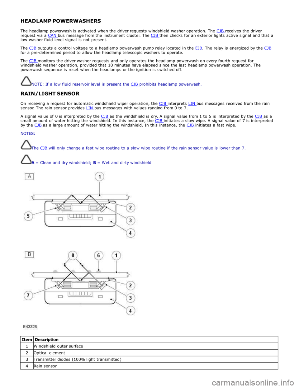
On receiving a request for automatic windshield wiper operation, the CJB interprets LIN bus messages received from the rain sensor. The rain sensor provides LIN bus messages with values ranging from 0 to 7.
A signal value of 0 is interpreted by the CJB as the windshield is dry. A signal value from 1 to 5 is interpreted by the CJB as a small amount of water hitting the windshield. In this instance, the CJB initiates a slow wipe. A signal value of 7 is interpreted by the CJB as a large amount of water hitting the windshield. In this instance, the CJB initiates a fast wipe. NOTES:
The CJB will only change a fast wipe routine to a slow wipe routine if the rain sensor value is lower than 7.
A = Clean and dry windshield; B = Wet and dirty windshield
Item Description 1 Windshield outer surface 2 Optical element 3 Transmitter diodes (100% light transmitted) 4 Rain sensor