2010 JAGUAR XFR ignition
[x] Cancel search: ignitionPage 2415 of 3039

7 Window regulator motor – driver's door 8 Door module – LH (left-hand) rear passenger 9 Window control switch - LH rear passenger 10 Window regulator motor – LH rear passenger 11 Door module – front passenger 12 Window control switches - front passenger 13 Window regulator motor – front passenger 14 Door module – RH (right-hand) rear passenger 15 Window control switch - RH rear passenger 16 Window regulator motor – RH rear passenger
Door Windows System Operation
All windows can be operated individually, or by the driver’s window control switch. The operation of the windows is proportional
to the switch activation. All windows can be controlled by ‘one touch’ in an upward or downward direction. When the ‘one
touch’ operation is activated in the upwards direction ‘pinch protection‘ is enabled. If a pinch condition is detected the window
will automatically stop and travel downwards to a pre-determined position.
When the rear window ‘one touch’ operation is activated in the downward direction, the window will drop a limited way down.
This is the comfort setting to achieve optimum noise levels when vehicle is in motion with rear windows open. Further ‘one
touch’ operation will drop the window all the way down. (Only applies to vehicles post VIN R99740) The ‘one touch’ operation
to activate the upward direction will fully close the window.
Electric window operation is enabled while the ignition is in power mode 4 and 6. When the switches in the driver's door are
used to operate the passenger windows, the driver's door module outputs a related message on the LIN (local interconnect
network) bus and medium speed CAN (controller area network) bus. The passenger door module responds to the message by
operating the appropriate window. When the child lock is engaged, the rear door modules ignore inputs from the rear window
switches.
End of travel shut off
End of travel shut-off for the window motors is determined by monitoring the current draw of the motors. Each time it switches
on a window motor, the door module measures the window motor current for a preset time. The maximum value measured
within that time is stored as the switch-on current. When the window motor current next exceeds the switch-on current, the
door module assumes the window has reached the end of its travel and switches off the power supply to the window motor
even if a window switch is still being activated.
Anti-trap
The anti-trap function is enabled for window closing in both the inching and one-shot modes. If the anti-trap feature is
activated while a window is closing, the window motor is reversed for a preset period.
A Hall sensor, located in the window regulator motor, monitors the speed of the motor and if the speed decreases below a set
threshold, indicating an obstruction, the power feed to the motor is reversed so the window goes back down for preset time.
In an emergency the anti-trap function can be overridden by holding the window switch in the one-shot closed position.
After the battery has been disconnected it is necessary to initialize the door window motors to be able to operate the one-shot
up function.
Windshield Component Description
The windshield, manufactured from 5mm laminated green-tinted glass is positioned to the vehicle's body by two locator pins,
one in each top corner of the windshield. This allows for centralizing movement of the windshield across the car upon fitment.
The base of the windshield carries a leaf-screen retainer. The windshield is bonded and sealed to the vehicle body aperture
using Polyurethane (PU) adhesive. The windshield finisher is a three-sided extruded flip, taped onto the inner surface of the
glass; this helps to centralize the glass in the aperture.
Two variants of windshield are available:
standard, and
heated.
Refer to: Control Components (412-01 Climate Control, Description and Operation).
Interior Mirror and Rain Sensor
The interior mirror and rain sensor mounting positions are located at the top of the windshield.
Refer to: Wipers and Washers (501-16 Wipers and Washers, Description and Operation).
Page 2493 of 3039

Item Description Note: A = Hardwired; N = Medium speed CAN 1 Battery 2 Megafuse (250 A) 3 CJB 4 Radio frequency receiver 5 Keylesss vehicle module 6 Door handle, lock/unlock switch and antenna - front passenger 7 Door latch, fast latch - front passenger 8 Door latch, fast latch - RH rear passenger 9 Door handle, lock/unlock switch and antenna - RH rear passenger 10 Door latch, fast latch - LH rear passenger 11 Door handle, lock/unlock switch and antenna - LH rear passenger 12 Door latch, fast latch - driver door 13 Door handle, lock/unlock switch and antenna - driver door
System Operation
The hinged panels are secured with latches and strikers. A remotely operated central locking system controls the locking and
unlocking of the door and luggage compartment latches. A radio frequency Smart Key allows the vehicle to be locked and
unlocked by pressing the appropriate handset buttons. Two levels of central locking system are available: remote central
locking and an optional passive entry system.
The passive entry and associated passive start system allows the driver to unlock and start the vehicle without using a vehicle
key in a door-lock or ignition switch. The passive entry system is an optional fitment while the passive start system is a
standard fitment on all vehicles. The passive start system is combined with the passive anti-theft immobilization system.
Refer to: Anti-Theft - Passive (419-01B Anti-Theft - Passive, Description and Operation).
Emergency access to the vehicle is provided by two concealed key barrels: one located in the front left-hand door handle and
one located on the underside of the luggage compartment lid finisher. An emergency, removable key blade is fitted into the
Smart Key.
Operation of either key barrel unlocks the vehicle but does not disarm the alarm system. The key barrels in the door and
luggage compartment lid are concealed by a plastic cover which can be removed by inserting the blade of the emergency key
into a slot in the cover.
Locking and unlocking conditions using the emergency key in the door key barrel:
If the alarm is not armed the vehicle can be centrally unlocked.
If the alarm is armed the door only can be opened and the alarm will be triggered.
The vehicle cannot be double locked or the alarm system armed using the emergency key.
The vehicle can be centrally locked and unlocked from inside using the interior handle release levers on the front doors only.
Central locking and unlocking can also be performed using lock and unlock buttons on the vehicle's fascia. The driver can select
locking options, single point entry or drive away locking for example, from a menu available on the touch screen.
Central Locking – Radio Frequency Remote System
The radio frequency central locking system, provides locking and unlocking of the vehicle from inside and outside of the
vehicle. The system is operated using buttons on the Smart Key, which transmits radio frequency signals to the central locking
radio frequency receiver.
The system provides additional security by double-locking the doors from outside the vehicle if the lock button, on the Smart
Key, is pressed twice within 3 seconds; this function is not applicable in North American Specification (NAS) and Japanese
markets.
Additional buttons on the Smart Key provide for the convenience operation of the luggage compartment lid release, headlamp
delay and panic alarm functions. A global open or close feature is also available in certain markets using the lock/unlock
buttons.
Passive Entry
On vehicles fitted with the optional passive entry system, the vehicle can be unlocked without the use of a key blade or
pressing buttons on the Smart Key. The Smart Key operates the passive entry system in addition to the passive start system.
Refer to: Anti-Theft - Passive (419-01B Anti-Theft - Passive, Description and Operation).
The passive entry system is controlled by the keyless vehicle module and five low frequency antennas. One antenna located in
each door handle and one antenna located behind the rear bumper cover.
When a vehicle door handle is pulled to the first five-percent of its travel and the Smart Key is within one meter of the handle;
the Smart Key receives the low-frequency signal transmitted from the keyless vehicle module. The Smart Key responds with a
radio frequency transmission of its authorization code. The radio frequency signal is received by the central locking radio-
frequency receiver and passed to the keyless vehicle module which checks and approves the code as valid. Once the handle is
Page 2538 of 3039
HEADLAMP POWERWASHERS
The headlamp powerwash is activated when the driver requests windshield washer operation. The CJB receives the driver request via a CAN bus message from the instrument cluster. The CJB then checks for an exterior lights active signal and that a low washer fluid level signal is not present.
The CJB outputs a control voltage to a headlamp powerwash pump relay located in the EJB. The relay is energized by the CJB for a pre-determined period to allow the headlamp telescopic washers to operate.
The CJB monitors the driver washer requests and only operates the headlamp powerwash on every fourth request for windshield washer operation, provided that 10 minutes have elapsed since the last headlamp powerwash operation. The
powerwash sequence is reset when the headlamps or the ignition is switched off.
NOTE: If a low fluid reservoir level is present the CJB prohibits headlamp powerwash.
RAIN/LIGHT SENSOR
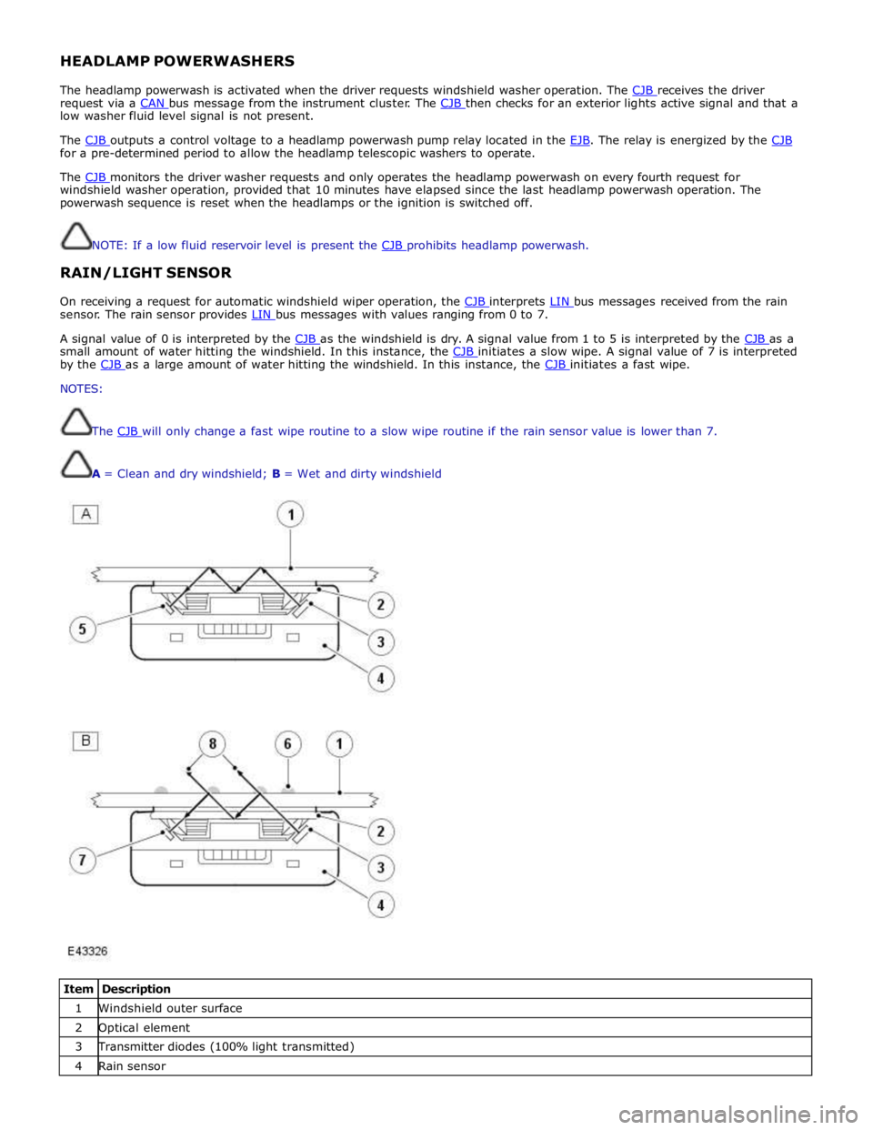
On receiving a request for automatic windshield wiper operation, the CJB interprets LIN bus messages received from the rain sensor. The rain sensor provides LIN bus messages with values ranging from 0 to 7.
A signal value of 0 is interpreted by the CJB as the windshield is dry. A signal value from 1 to 5 is interpreted by the CJB as a small amount of water hitting the windshield. In this instance, the CJB initiates a slow wipe. A signal value of 7 is interpreted by the CJB as a large amount of water hitting the windshield. In this instance, the CJB initiates a fast wipe. NOTES:
The CJB will only change a fast wipe routine to a slow wipe routine if the rain sensor value is lower than 7.
A = Clean and dry windshield; B = Wet and dirty windshield
Item Description 1 Windshield outer surface 2 Optical element 3 Transmitter diodes (100% light transmitted) 4 Rain sensor
Page 2542 of 3039
On vehicles with headlamp powerwash, each headlamp assembly is fitted with a headlamp powerwasher. The powerwasher is
located on the underside of the headlamp assembly. The powerwasher is located in a clip at the front of the headlamp and
secured with 2 self tapping screws to the headlamp body.
The powerwasher is a telescopic unit which extends forwards from the headlamp assembly under washer fluid pressure
supplied by the headlamp powerwash pump. When the pump pressure decreases the powerwasher is automatically retracted
back into the housing. The outer end of the powerwasher is fitted with a trim which blends the powerwasher into the headlamp
when it is not operating. The powerwasher has two washer jets which direct washer fluid under high pressure onto the
headlamp lens when the powerwasher is extended.
RAIN/LIGHT SENSOR
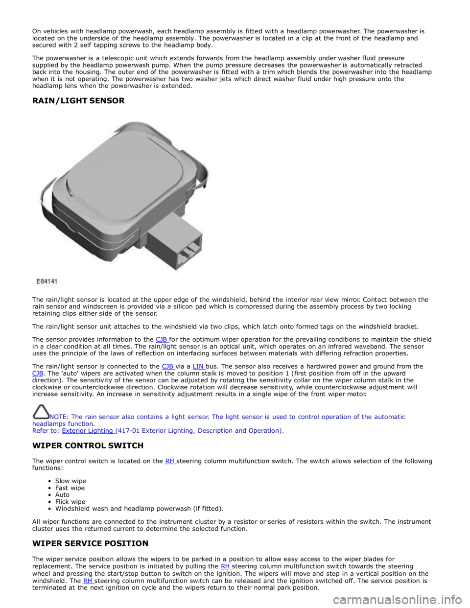
The rain/light sensor is located at the upper edge of the windshield, behind the interior rear view mirror. Contact between the
rain sensor and windscreen is provided via a silicon pad which is compressed during the assembly process by two locking
retaining clips either side of the sensor.
The rain/light sensor unit attaches to the windshield via two clips, which latch onto formed tags on the windshield bracket.
The sensor provides information to the CJB for the optimum wiper operation for the prevailing conditions to maintain the shield in a clear condition at all times. The rain/light sensor is an optical unit, which operates on an infrared waveband. The sensor
uses the principle of the laws of reflection on interfacing surfaces between materials with differing refraction properties.
The rain/light sensor is connected to the CJB via a LIN bus. The sensor also receives a hardwired power and ground from the CJB. The 'auto' wipers are activated when the column stalk is moved to position 1 (first position from off in the upward direction). The sensitivity of the sensor can be adjusted by rotating the sensitivity collar on the wiper column stalk in the
clockwise or counterclockwise direction. Clockwise rotation will decrease sensitivity, while counterclockwise adjustment will
increase sensitivity. An increase in sensitivity adjustment results in a single wipe of the front wiper motor.
NOTE: The rain sensor also contains a light sensor. The light sensor is used to control operation of the automatic
headlamps function.
Refer to: Exterior Lighting (417-01 Exterior Lighting, Description and Operation).
WIPER CONTROL SWITCH
The wiper control switch is located on the RH steering column multifunction switch. The switch allows selection of the following functions:
Slow wipe
Fast wipe
Auto
Flick wipe
Windshield wash and headlamp powerwash (if fitted).
All wiper functions are connected to the instrument cluster by a resistor or series of resistors within the switch. The instrument
cluster uses the returned current to determine the selected function.
WIPER SERVICE POSITION
The wiper service position allows the wipers to be parked in a position to allow easy access to the wiper blades for
replacement. The service position is initiated by pulling the RH steering column multifunction switch towards the steering wheel and pressing the start/stop button to switch on the ignition. The wipers will move and stop in a vertical position on the
windshield. The RH steering column multifunction switch can be released and the ignition switched off. The service position is terminated at the next ignition on cycle and the wipers return to their normal park position.
Page 2562 of 3039

Roof opening panel System Operation
Operation of the roof opening panel is controlled by the roof opening panel control module, which is integral with the motor.
The control module receives inputs from the CJB, which provides an 'open' or 'close' signal for remote handset operation, and
an 'enable' signal when the vehicle enters power mode 6.
The control module also receives a vehicle speed signal from the ABS module. The vehicle speed signal is used by the control
module to calibrate the anti-trap feature.
If the battery is disconnected, or the power supply is interrupted while the roof opening panel is in a partially open position,
the motor and control module will need to be calibrated to restore full functionality. To recalibrate:
1. Switch ignition on.
2. Press the front of the switch, so the roof opening panel is the tilt position, and then release the switch.
3. Press the front of the switch and hold for thirty seconds.
4. After thirty seconds the roof opening panel will begin to move. Keep the front of the switch pressed until the roof
opening panel has fully opened and then closed.
5. Once the open/close cycle has completed and the roof opening panel has stopped moving, release the switch.
6. The roof opening panel can now be operated as normal.
Drain hoses are connected to the front and rear corners of the roof opening panel frame. The drain hoses are located inside of
the cabin on the 'A' and 'D' post pillars to allow water, which has collected in the frame, to escape. One-way valves fitted to
the end of each drain hose, prevent the ingress of dirt and moisture.
Rear window sunblind
The powered rear window sunblind is operated through a switch in the roof console. Power to the sunblind motor is provided by
a pair of relays located in the CJB when the vehicle enters power mode 4. The sunblind motor is located beneath the rear parcel
shelf and is supplied as a sealed unit with the sunblind mechanism.
If the battery is disconnected or a replacement sunblind is fitted, the motor will require re-calibrating. To re-calibrate the
motor the sunblind should be powered through two-full cycles of movement.
Roof opening panel, motor Component Description
The roof opening panel motor has a worm drive which drives a gear in the cast housing attached to the end of the motor. The
gear has a small pinion gear attached to the outer part of its spindle. The pinion engages with two cables to form a rack and
pinion drive. Rotation of the motor turns the pinion which in turn drives the cables in the required direction.
The two cables are attached either side of the pinion. One end of each cable is attached to the guide; the opposite end of
each cable is held in position on the pinion by a metal insert in the frame. The cables run in channels, in the panel frame to
the guides. As the panel is closed the cables are pushed through channels in the front of the frame. The displaced cable is
guided into a further two channels in the frame, which protect the cable and prevent it from snagging. The cables
manufactured from rigid spring steel can pull as well as push the panel along the guides.
The motor contains a micro-switch and Hall effect sensor. Signals received from these components enable the control module
to calculate the exact position of the roof opening panel. The Hall effect sensor is also responsible for the operation of the
anti-trap function.
If the anti-trap feature is activated while the roof opening panel is closing, the panel is reversed for 200mm or as far as
possible. The Hall effect sensor, located in the motor, monitors the speed of the motor and if the speed decreases below a set
threshold, indicating an obstruction, the power feed to the motor is reversed so the panel goes back. In an emergency the
anti-trap function can be overridden by holding the switch in the closed position.
Roof opening panel, control module
The roof opening panel control module is integrated within the motor. The control module receives inputs from the CJB, which
provides an 'open' or 'close' signal for remote handset operation, and an 'enable' signal when the vehicle enters power mode 6.
The control module also contains the algorithm for the anti-trap system and receives a vehicle speed signal from the ABS
module. The vehicle speed signal is used by the control module to calibrate the anti-trap feature.
Page 2595 of 3039
Safety Belt System - Safety Belt System
Diagnosis and Testing
Principle of Operation Published: 13-Jun-2013
For a detailed description of the seatbelt system and operation, refer to the relevant description and operation section of the
workshop manual REFER to: (501-20A Safety Belt System)
Safety Belt System (Description and Operation), Safety Belt System (Description and Operation), Safety Belt System (Description and Operation).
Safety Information
WARNINGS:
To avoid accidental deployment the back-up power supply must be depleted before beginning any work on the SRS system
or its components. Failure to follow this instruction may result in personal injury
Do not use a multimeter to probe an SRS module. It is possible for the power from the multimeter battery to trigger the
activation of the module. Failure to follow this instruction may result in personal injury
NOTE: Do not to use a cellular phone or to have a cellular phone in close proximity when working on the SRS system or
components
Power supply depletion
Before beginning any work on the SRS system or related components:
1. Remove the ignition key
2. Disconnect the battery leads, ground first
3. Wait 2 minutes for the power circuit to discharge
There are comprehensive instructions on the correct procedures for SRS system repairs, refer to the relevant section of the
workshop manual
Inspection and Verification
CAUTION: Diagnosis by substitution from a donor vehicle is NOT acceptable. Substitution of control modules does not
guarantee confirmation of a fault and may also cause additional faults in the vehicle being checked and/or the donor vehicle
NOTE: Check and rectify basic faults before beginning diagnostic routines including pinpoint tests
1. Verify the customer concern by operating the seatbelt
2. Visually inspect for obvious signs of mechanical or electrical damage
Visual Inspection
Mechanical Electrical
Check for the installation of non-standard accessories which may affect or
obstruct the function of the seatbelt system
Frayed or damaged webbing
Missing or damaged button stop
Pretensioner(s) Buckles/Stalks
Fuses
Wiring harness fault
Correct engagement of electrical
connectors
Loose or corroded connections
Warning lamp bulb(s)
Impact sensor(s)
Buckle sensor(s)
Pretensioner(s)
Belt tension sensor(s)
Restraints control module
3. If an obvious cause for an observed or reported concern is found, correct the cause (if possible) before proceeding to
the next step
4. If the cause is not visually evident, carry out the test methods described below, alternatively check for diagnostic
trouble codes and refer to the relevant diagnostic trouble code index
Page 2616 of 3039
and the safety belt buckle sensor. Based on this data, the RCM decides which level of airbag module deployment is required and forwards the information to the second area, the deployment handler.
The deployment handler evaluates the status of the seat track position sensor and safety belt buckle sensors before a decision
is made about which restraints should finally be deployed.
Data from the side crash sensors is used by the RCM in conjunction with acceleration data from the RCM internal accelerometer to make a deployment decision. The RCM processes the acceleration data and subject to an impact being of high enough severity, decides whether the side airbag module should be deployed.
On board testing of the airbag modules, front safety belt pretensioner firing circuits, warning indicator circuits and module
status (the crash and side impact sensors perform basic self-tests) is performed by the RCM together with the storing of fault codes.
The RCM drives the SRS indicator on the instrument pack via a CAN signal. If the warning lamp fails, a fault code is recorded and a warning tone is sounded in place of the lamp if a further fault occurs. It also provides a temporary back-up power supply
to operate the airbag modules in the event that in crash conditions, the battery supply is lost. In the event of a crash, it
records certain data which can be accessed via the diagnostic connector.
A safing sensor in the RCM provides confirmation of an impact to verify if airbag and pretensioner activation is necessary. A roll-over sensor monitors the lateral attitude of the vehicle. Various firing strategies are employed by the RCM to ensure that during an accident only the appropriate airbags and pretensioners are fired. The firing strategy used also depends on the
inputs from the safety belt switches and the occupant monitoring system.
An energy reserve in the RCM ensures there is always a minimum of 150 milliseconds of stored energy available if the power supply from the ignition switch is disrupted during a crash. The stored energy is sufficient to produce firing signals for the
driver airbag, the passenger airbag and the safety belt pretensioners.
When the ignition is switched on, the RCM performs a self-test and then performs cyclical monitoring of the system. If a fault is detected the RCM stores a related fault code and illuminates the airbag warning indicator. The faults can be retrieved by the recommended Jaguar diagnostic tool over the CAN bus. If a fault that could cause a false fire signal is detected, the RCM disables the respective firing circuit, and keeps it disabled during a crash event.
Clock Spring
The clockspring is installed on the steering column to provide the electrical interface between the fixed wiring harness of the
steering column and the components that rotate with the steering wheel, i.e. the driver airbag, the horn and the steering
wheel switch packs.
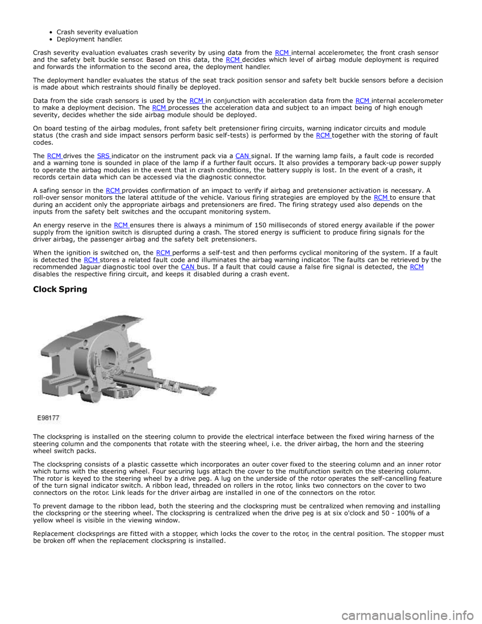
The clockspring consists of a plastic cassette which incorporates an outer cover fixed to the steering column and an inner rotor
which turns with the steering wheel. Four securing lugs attach the cover to the multifunction switch on the steering column.
The rotor is keyed to the steering wheel by a drive peg. A lug on the underside of the rotor operates the self-cancelling feature
of the turn signal indicator switch. A ribbon lead, threaded on rollers in the rotor, links two connectors on the cover to two
connectors on the rotor. Link leads for the driver airbag are installed in one of the connectors on the rotor.
To prevent damage to the ribbon lead, both the steering and the clockspring must be centralized when removing and installing
the clockspring or the steering wheel. The clockspring is centralized when the drive peg is at six o'clock and 50 - 100% of a
yellow wheel is visible in the viewing window.
Replacement clocksprings are fitted with a stopper, which locks the cover to the rotor, in the central position. The stopper must
be broken off when the replacement clockspring is installed.
Page 2617 of 3039
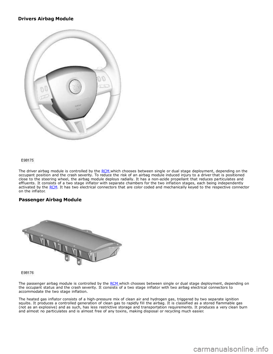
occupant position and the crash severity. To reduce the risk of an airbag module induced injury to a driver that is positioned
close to the steering wheel, the airbag module deploys radially. It has a non-azide propellant that reduces particulates and
effluents. It consists of a two stage inflator with separate chambers for the two inflation stages, each being independently
activated by the RCM. It has two electrical connectors that are color coded and mechanically keyed to the respective connector on the inflator.
Passenger Airbag Module
The passenger airbag module is controlled by the RCM which chooses between single or dual stage deployment, depending on the occupant status and the crash severity. It consists of a two stage inflator with two airbag electrical connectors to
accommodate the two stage inflation.
The heated gas inflator consists of a high-pressure mix of clean air and hydrogen gas, triggered by two separate ignition
squibs. It produces a controlled generation of clean gas to rapidly fill the airbag. It is classified as a stored flammable gas
(not as an explosive) and as such, has less restrictive storage and transportation requirements. It produces a very clean burn
and almost no particulates and is almost free of any toxins, making disposal or recycling much easier. Drivers Airbag Module