2010 JAGUAR XFR check engine light
[x] Cancel search: check engine lightPage 725 of 3039

With the control valve (7) OPEN and the engine idling, the following system pressures may be checked:
During turning when static (dry parking pressure).
When the steering is held on full lock (maximum system pressure or pressure relief).
With the steering at rest (idle pressure or back pressure).
CAUTIONS:
To avoid excessive heating of the power steering pump when checking the pressure, do not close the valve for more than
5 seconds maximum.
When checking the pump pressure DO NOT drive the vehicle with the test equipment installed.
With the control valve (7) CLOSED the power steering pump maximum output pressure can be checked.
Removing Test Equipment
To remove the test equipment:
Install a hose clamp on the reservoir to power steering pump hose.
Removing the test equipment is a reversal of the installation instructions.
Install a new 'O' ring seal (9) to the power steering pump high pressure outlet to hose connection.
Install the original hose to the power steering pump.
Remove the clamp from the reservoir to the power steering pump hose.
Top-up the reservoir fluid.
Bleed the power steering system.
REFER to: Power Steering System Bleeding (211-00 Steering System - General Information, General Procedures).
Description of Terms General Steering System Noises
Boom
Rhythmic sound like a drum roll or distant thunder. May cause pressure on the ear drum.
Buzz
Low-pitched sound, like a bee. Usually associated with vibrations.
Chatter
Rapidly repeating metallic sound.
Chuckle
Rapid noise that sounds like a stick against the spokes of a spinning bicycle wheel.
Chirp
High pitched rapidly repeating sound, like chirping birds.
Click
Light sound, like a ball point pen being clicked.
Click/Thump
Heavy metal-to-metal sound, like a hammer striking steel.
Grind
Abrasive sound, like a grinding wheel or sandpaper rubbing against wood.
Groan/Moan
Continuous, low-pitched humming sound.
Groan/Howl
Low, guttural sound, like an angry dog.
Hiss
Continuous sound like air escaping from a tire valve.
Page 1372 of 3039
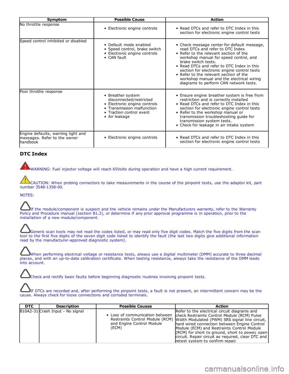
Symptom Possible Cause Action No throttle response
Electronic engine controls
Read DTCs and refer to DTC Index in this
section for electronic engine control tests Speed control inhibited or disabled
Default mode enabled
Speed control, brake switch
Electronic engine controls
CAN fault
Check message center for default message,
read DTCs and refer to DTC Index
Refer to the relevant section of the
workshop manual for speed control, and
brake switch tests.
Read DTCs and refer to DTC Index in this
section for electronic engine control tests
Refer to the relevant section of the
workshop manual and the electrical wiring
diagrams to perform CAN network tests. Poor throttle response
Breather system
disconnected/restricted
Electronic engine controls
Transmission malfunction
Traction control event
Air leakage
Ensure engine breather system is free from
restriction and is correctly installed
Read DTCs and refer to DTC Index in this
section for electronic engine control tests
Refer to the workshop manual or
transmission troubleshooting guide for
transmission system tests.
Check for leakage in air intake system Engine defaults, warning light and
messages. Refer to the owner
handbook
Electronic engine controls
Read DTCs and refer to DTC Index in this
section for electronic engine control tests DTC Index
WARNING: Fuel injector voltage will reach 65Volts during operation and have a high current requirement.
CAUTION: When probing connectors to take measurements in the course of the pinpoint tests, use the adaptor kit, part
number 3548-1358-00.
NOTES:
If the module/component is suspect and the vehicle remains under the Manufacturers warranty, refer to the Warranty
Policy and Procedure manual (section B1.2), or determine if any prior approval programme is in operation, prior to the
installation of a new module/component.
Generic scan tools may not read the codes listed, or may read only five digit codes. Match the five digits from the scan
tool to the first five digits of the seven digit code listed to identify the fault (the last two digits give additional information
read by the manufacturer-approved diagnostic system).
When performing electrical voltage or resistance tests, always use a digital multimeter (DMM) accurate to three decimal
places, and with an up-to-date calibration certificate. When testing resistance, always take the resistance of the DMM leads
into account.
Check and rectify basic faults before beginning diagnostic routines involving pinpoint tests.
If DTCs are recorded and, after performing the pinpoint tests, a fault is not present, an intermittent concern may be the
cause. Always check for loose connections and corroded terminals.
DTC Description Possible Causes Action B10A2-31 Crash Input - No signal
Loss of communication between
Restraints Control Module (RCM)
and Engine Control Module
(ECM) Refer to the electrical circuit diagrams and
check Restraints Control Module (RCM) Pulse
Width Modulated (PWM) SRS signal line circuit,
hard wired connection between Engine Control
Module (ECM) and Restraints Control Module
(RCM) for short to ground, short to power, open
circuit. Repair circuit as required, clear DTC and
retest system to confirm repair.
Page 1486 of 3039
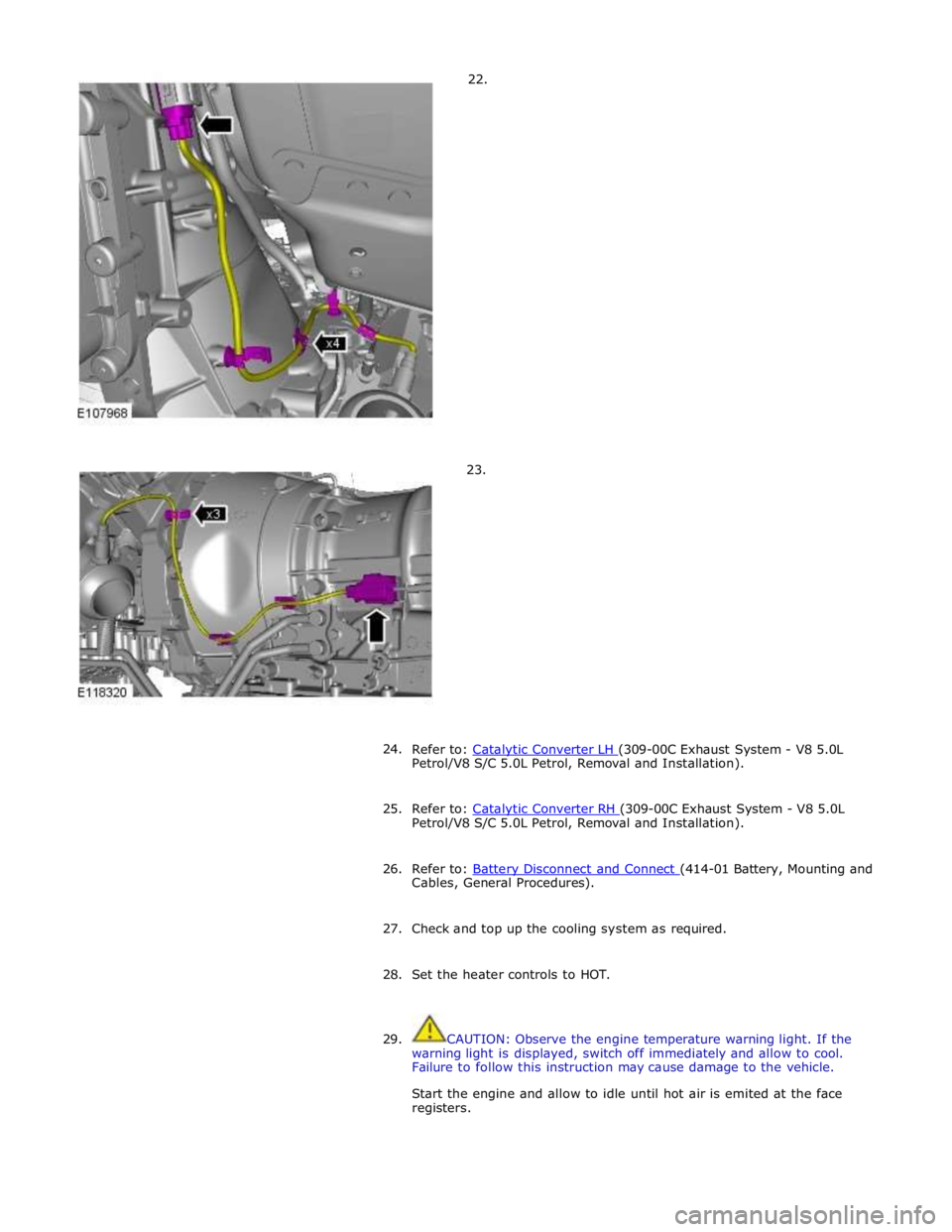
22.
23.
24.
Refer to: Catalytic Converter LH (309-00C Exhaust System - V8 5.0L Petrol/V8 S/C 5.0L Petrol, Removal and Installation).
25. Refer to: Catalytic Converter RH (309-00C Exhaust System - V8 5.0L Petrol/V8 S/C 5.0L Petrol, Removal and Installation).
26. Refer to: Battery Disconnect and Connect (414-01 Battery, Mounting and Cables, General Procedures).
27. Check and top up the cooling system as required.
28. Set the heater controls to HOT.
29. CAUTION: Observe the engine temperature warning light. If the
warning light is displayed, switch off immediately and allow to cool.
Failure to follow this instruction may cause damage to the vehicle.
Start the engine and allow to idle until hot air is emited at the face
registers.
Page 1487 of 3039
30. CAUTION: Observe the engine temperature warning light. If the
warning light is displayed, switch off immediately and allow to cool.
Failure to follow this instruction may cause damage to the vehicle.
Raise the engine speed to 2000 RPM and maintain at 2000 RPM until the
engine cooling fan operates.
31. CAUTION: Switch off the engine and allow the coolant temperature
to go cold.
Switch the engine off and allow to cool.
32. Visually check the engine and cooling system for signs of coolant
leakage.
33. WARNINGS:
When releasing the cooling system pressure, cover the coolant
expansion tank cap with a thick cloth.
Since injury such as scalding could be caused by escaping steam or
coolant, make sure the vehicle cooling system is cool prior to carrying
out this procedure.
CAUTIONS:
Make sure the coolant level remains above the "COLD FILL RANGE"
lower level mark.
Anti-freeze concentration must be maintained at 50%.
NOTE: When the cooling system is warm, the coolant will be
approximately 10mm above the upper level mark on the expansion tank
with the cap removed.
Check and top-up the coolant if required.
34. Refer to: Transmission Fluid Level Check (307-01B Automatic Transmission/Transaxle - TDV6 3.0L Diesel /V8 5.0L Petrol/V8 S/C 5.0L
Petrol, General Procedures).
Page 1502 of 3039
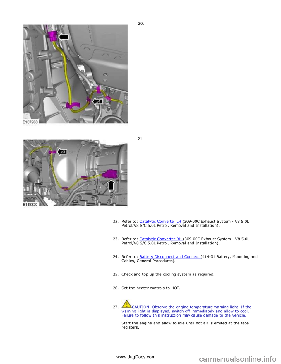
20.
21.
22.
Refer to: Catalytic Converter LH (309-00C Exhaust System - V8 5.0L Petrol/V8 S/C 5.0L Petrol, Removal and Installation).
23. Refer to: Catalytic Converter RH (309-00C Exhaust System - V8 5.0L Petrol/V8 S/C 5.0L Petrol, Removal and Installation).
24. Refer to: Battery Disconnect and Connect (414-01 Battery, Mounting and Cables, General Procedures).
25. Check and top up the cooling system as required.
26. Set the heater controls to HOT.
27. CAUTION: Observe the engine temperature warning light. If the
warning light is displayed, switch off immediately and allow to cool.
Failure to follow this instruction may cause damage to the vehicle.
Start the engine and allow to idle until hot air is emited at the face
registers. www.JagDocs.com
Page 1503 of 3039
28. CAUTION: Observe the engine temperature warning light. If the
warning light is displayed, switch off immediately and allow to cool.
Failure to follow this instruction may cause damage to the vehicle.
Raise the engine speed to 2000 RPM and maintain at 2000 RPM until the
engine cooling fan operates.
29. CAUTION: Switch off the engine and allow the coolant temperature
to go cold.
Switch the engine off and allow to cool.
30. Visually check the engine and cooling system for signs of coolant
leakage.
31. WARNINGS:
When releasing the cooling system pressure, cover the coolant
expansion tank cap with a thick cloth.
Since injury such as scalding could be caused by escaping steam or
coolant, make sure the vehicle cooling system is cool prior to carrying
out this procedure.
CAUTIONS:
Make sure the coolant level remains above the "COLD FILL RANGE"
lower level mark.
Anti-freeze concentration must be maintained at 50%.
NOTE: When the cooling system is warm, the coolant will be
approximately 10mm above the upper level mark on the expansion tank
with the cap removed.
Check and top-up the coolant if required.
32. Refer to: Transmission Fluid Level Check (307-01B Automatic Transmission/Transaxle - TDV6 3.0L Diesel /V8 5.0L Petrol/V8 S/C 5.0L
Petrol, General Procedures).
Page 1651 of 3039

DTC Description Possible Causes Action for further assistance P0501-62
Vehicle Speed Sensor A
Range/Performance - Signal
compare failure
Vehicle speed - range
performance
Check ABS/TCM for related DTCs and refer
to relevant DTC Index P0504-00 Brake Switch A / B Correlation
- No sub type information
The brake pressure reading
does not agree with the
brake light switch value
Carry out any pinpoint tests associated with
this DTC using the manufacturer approved
diagnostic system. Refer to the electrical
circuit diagrams and check brake switch
circuits for short, open circuit, high
resistance P0504-01 Brake Switch A / B Correlation
- General electrical failure
Brake switch high fault:
- Brake lights stuck
on
- Gearshift interlock
inoperative
- Speed control
inoperative
Brake switch low fault:
- Brake lights
inoperative
- Gearshift stuck in
Park
- Reduced engine
braking
Carry out any pinpoint tests associated with
this DTC using the manufacturer approved
diagnostic system. Refer to the electrical
circuit diagrams and check brake switch
circuits for short, open circuit, high
resistance P0566-00
Cruise Control OFF Signal - No
sub type information
Speed control Cancel
switch 2 stuck closed
Refer to the electrical circuit diagrams and
check speed control switch circuits for short,
open circuit. Check for stuck switch. Check
and install a new speed control switch as
required P0567-00
Cruise Control DECREASE
DISTANCE Signal - No sub
type information
Speed control Resume
switch 7 stuck closed
Refer to the electrical circuit diagrams and
check speed control switch circuits for short,
open circuit. Check for stuck switch. Check
and install a new speed control switch as
required P0568-00
Cruise Control INCREASE
DISTANCE Signal - No sub
type information
Speed control Accel Set
Plus Switch 6 stuck closed
Check and install a new speed control
switch as required P0569-00
Cruise Control COAST Signal -
No sub type information
Speed control Coast Set
Minus switch 3 stuck
closed
Refer to the electrical circuit diagrams and
check speed control switch circuits for short,
open circuit. Check for stuck switch. Check
and install a new speed control switch as
required P056A-00
Cruise Control INCREASE
DISTANCE Signal - No sub
type information
Speed control Headway
Plus switch 4 stuck closed
Refer to the electrical circuit diagrams and
check speed control switch circuits for short,
open circuit. Check for stuck switch. Check
and install a new speed control switch as
required P056B-00
Cruise Control DECREASE
DISTANCE Signal - No sub
type information
Speed control Headway
Minus switch 5 stuck
closed
Refer to the electrical circuit diagrams and
check speed control switch circuits for short,
open circuit. Check for stuck switch. Check
and install a new speed control switch as
required P0571-62
Brake Switch A Circuit - Signal
compare failure
Plausibility error
Refer to the electrical circuit diagrams and
check brake light switch signal circuits for
short, open circuit. Check and install a new
brake light switch as required P0575-01
Cruise Control Input Circuit -
General electrical failure
General electrical failure
Check speed control system for related
DTCs and refer to relevant DTC Index. Carry
out CAN network integrity tests using the
Page 1785 of 3039
The functionality for each of the above warning indicators is described in the following sections:
1 and 2. Turn Signal Indicators
The turn signal indicators are controlled by the CJB on receipt of medium speed CAN bus signals from the instrument cluster.
The instrument cluster outputs a voltage to the turn signal indicator switch. The switch contains resistors of different values.
When the switch is operated in either the LH or RH direction, the voltage is passed to a ground connection in the instrument cluster which detects the reduced voltage supplied via the resistors. When the turn signal indicator switch is operated in the
LH or RH direction, the instrument cluster detects the ground voltage and determines whether a LH or RH selection is made.
The instrument cluster transmits a medium speed CAN message to the CJB for operation of the applicable turn signal indicators. The message can contain a number of states for each possible switch position and also an out of range low and
high state for circuit faults and an initial value for the switch neutral position. The turn signal indicators are not subject to the
3 second indicator check when the ignition is switched on.
The RJB (rear junction box) software controls the flash rate of the warning indicator which sends 'ON' and 'OFF' signals to the
instrument cluster which flashes the indicators in a green color. During normal operation, the warning indicator flashes slowly,
accompanied simultaneously by a sound from the instrument cluster sounder. If a fault exists, the RJB transmits a message to the instrument cluster which responds by displaying an appropriate message in the message center.
The hazard warning indicators are controlled by the CJB on receipt of a completed ground path from the hazard warning indicator switch. The CJB outputs a medium speed CAN message to the instrument cluster which operates both the LH and RH turn signal indicators simultaneously. The hazard warning indicators can operate with the ignition switched off, therefore the
CAN message from the CJB will also carry a 'wake-up' message for the instrument cluster. 3. Brake Warning Indicator
This warning indicator is displayed in a red or amber color (dependant on market) as a brake symbol in all markets except
United States of America (USA) which have the word 'BRAKE' in place of the symbol. The indicator is controlled by high speed
CAN messages from the ABS module and the parking brake control module. The indicator is illuminated in a red color for a 3 second indicator check when the ignition is switched on.
The instrument cluster monitors the fluid level in the brake fluid reservoir using a hardwired level switch. If the fluid level falls
to below a determined level, the switch contact is broken and the ABS module detects the low fluid level condition. The instrument cluster illuminates the warning indicator and simultaneously displays a 'BRAKE FLUID LOW' message in the
message center.
NOTE: If both the brake warning indicator and the ABS warning indicator illuminate simultaneously, a major fault in the brake system will have occurred.
The warning indicator also displays parking brake status. When the parking brake is applied, the warning indicator will be
illuminated by the instrument cluster and, if the vehicle is moving, the message 'PARK BRAKE APPLIED' will be also displayed
in the message center in response to a CAN message from the parking brake control module.
If a condition exists where the parking brake cannot be applied, the parking brake control module issues a CAN message to the instrument cluster which flashes the warning lamp on and off and is accompanied with a message 'CANNOT APPLY PARK BRAKE'.
If a fault occurs in the parking brake system, the parking brake control module issues a CAN message to the instrument cluster which illuminates the warning indicator and displays the message 'PARK BRAKE FAULT' in the message
center.
4. Forward Alert Indicator
The forward alert system uses the components of the adaptive speed control system to alert the driver of the presence of a
vehicle ahead. The system can be turned on and off using a switch located in the auxiliary lighting switch when the adaptive
speed control system is off. The indicator is illuminated in an amber color for a 3 second indicator check when the ignition is
switched on.
The forward alert system is controlled by the adaptive speed control module. When the switch is pressed, the forward alert
system is activated and the adaptive speed control module issues a forward alert active message on the high speed CAN bus to the instrument cluster. The forward alert icon in the instrument cluster will illuminate in an amber color and a 'FORWARD
ALERT' message will be displayed in the message center. When the button is pressed a second time, the module issues a
forward alert off CAN message. The forward alert system will be deactivated, the forward alert icon will go off and a message 'FORWARD ALERT OFF' will be displayed in the message center.
5. Automatic Speed Limiter (ASL) Indicator
The ASL is controlled by the ECM (engine control module). An ASL switch is located in the floor console, adjacent to the gear
selector lever. When the ASL switch is pressed, this is sensed by the ECM which issues a high speed CAN message to the instrument cluster. The instrument cluster illuminates the ASL warning indicator in an amber color to show the driver that ASL
is active. The driver sets the required speed using the speed control SET +/- switches on the steering wheel. The selected
speed is shown by the message ' LIMITER SET XXX MPH / K/MH' in the message center. The indicator is illuminated in an
amber color for a 3 second indicator check when the ignition is switched on. ASL can be deselected by pressing the ASL switch,
by depressing the throttle pedal initiating kick-down or by pressing the 'cancel' switch on the steering wheel. The ASL indicator
will go off and the message center will display the message 'limiter cancelled' for 4 seconds. If a fault occurs in the ASL
system, the ECM will send a message to the instrument cluster to illuminate the ASL indicator and display the message 'LIMITER NOT AVAILABLE'.