2010 INFINITI QX56 upper link
[x] Cancel search: upper linkPage 624 of 4210

BODY REPAIRBRM-13
< SERVICE INFORMATION >
C
DE
F
G H
I
J
L
M A
B
BRM
N
O P
6. 2nd crossmember assembly
7. Front upper link mounting bracket RH/LH
8. Panhard rod bracket reinforcement
9. Bound bumper bracket RH/LH
10. Front brake hose bracket RH/LH
11. Panhard rod reinforcement
12. 4th crossmember gusset RH/LH
13. 2nd cab mounting bracket RH/LH
14. 3rd cab mounting bracket RH/LH
15. 4th cab mounting reinforcement RH/LH
16. 4th cab mounting bracket RH/LH
17. Rear suspension mounting bracket RH/LH
18. Rear brake hose bracket
19. Rear shock absorber bracket assembly RH/LH
20. Rear bound bumper bracket RH/LH
21. Rear bracket bumper reinforcement RH/LH
22. Cab mounting bracket assembly RH/LH
23. 9th crossmember assembly
24. Exhaust bracket assembly
25. Canister bracket, LH
26. 7th crossmember reinforcement
27. 7th crossmember assembly
28. 6th crossmember assembly
29. 4th crossmember gusset RH/LH
30. 4th crossmember assembly
31. 3rd crossmember assembly
32. Frame assembly
Corrosion ProtectionINFOID:0000000005147334
DESCRIPTION
To provide improved corrosion prevention, the follo wing anti-corrosive measures have been implemented in
NISSAN production plants. When repairing or replacing body panels, it is necessary to use the same anti-cor-
rosive measures.
ANTI-CORROSIVE PRECOATED ST EEL (GALVANNEALED STEEL)
To improve repairability and corrosion resistance, a new type of anti-
corrosive precoated steel sheet has been adopted replacing conven-
tional zinc-coated steel sheet.
Galvannealed steel is electroplated and heated to form Zinc-iron
alloy, which provides excellent and long term corrosion resistance
with cationic electrode position primer.
Nissan Genuine Service Parts are fabricated from galvannealed steel. Therefore, it is recommended that
GENUINE NISSAN PARTS or equivalent be used for panel replacement to maintain the anti-corrosive perfor-
mance built into the vehicle at the factory.
PHOSPHATE COATING TREATMENT AND CA TIONIC ELECTRODEPOSITION PRIMER
PIIA0093E
Revision: April 20092010 QX56
Page 2175 of 4210
DRIVE SHAFTFAX-9
< REMOVAL AND INSTALLATION >
CEF
G H
I
J
K L
M A
B
FA X
N
O P
DRIVE SHAFT
Removal and InstallationINFOID:0000000005148945
REMOVAL
1. Remove wheel and tire using power tool.
2. Remove engine under cover using power tool.
3. Remove wheel sensor harness from mount on knuckle and reposition aside. Refer to BRC-114, "
Removal
and Installation".
CAUTION:
Do not pull on wheel sensor harness.
4. Without disassembling the hydraulic lines, remove brake caliper using power tool. Reposition it aside with wire. Refer to BR-31, "
Removal and Installation of Brake Caliper and Rotor" .
NOTE:
Avoid depressing brake pedal while brake caliper is removed.
5. Remove coil spring and shock absorber assembly using power tool. Refer to FSU-14, "
Removal and
Installation" .
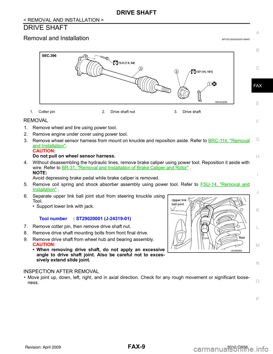
6. Separate upper link ball joint stud from steering knuckle using Tool.
• Support lower link with jack.
7. Remove cotter pin, then remove drive shaft nut.
8. Remove drive shaft mounting bolts from front final drive.
9. Remove drive shaft from wheel hub and bearing assembly. CAUTION:
• When removing drive shaf t, do not apply an excessive
angle to drive shaft joint. Also be careful not to exces-
sively extend slide joint.
INSPECTION AFTER REMOVAL
• Move joint up, down, left, right, and in axial directi on. Check for any rough movement or significant loose-
ness.
1. Cotter pin 2. Drive shaft nut3. Drive shaft
WDIA0329E
Tool number : ST29020001 (J-24319-01)
LEIA0095E
Revision: April 20092010 QX56
Page 2200 of 4210
FSU-1
SUSPENSION
C
DF
G H
I
J
K L
M
SECTION FSU
A
B
FSU
N
O PCONTENTS
FRONT SUSPENSION
PRECAUTION ....... ........................................2
PRECAUTIONS .............................................. .....2
Precaution for Supplemental Restraint System
(SRS) "AIR BAG" and "SEAT BELT PRE-TEN-
SIONER" ............................................................. ......
2
Precaution Necessary for Steering Wheel Rota-
tion After Battery Disconnect ............................... ......
2
Precaution .................................................................3
PREPARATION ............................................4
PREPARATION .............................................. .....4
Special Service Tool ........................................... ......4
Commercial Service Tool ..........................................4
SYMPTOM DIAGNOSIS ...............................5
NOISE, VIBRATION AND HARSHNESS
(NVH) TROUBLESHOOTING ........................ .....
5
NVH Troubleshooting Chart ................................ ......5
ON-VEHICLE MAINTENANCE .....................6
ON-VEHICLE SERVICE ................................. .....6
Front Suspension Parts ....................................... ......6
Front Wheel Alignment ..............................................6
UPPER BALL JOINT AND LOWER BALL
JOINT .................................................................
10
Inspection ............................................................ ....10
KNUCKLE ...................................................... ....12
On-Vehicle Inspection and Service ..................... ....12
ON-VEHICLE REPAIR .................................13
FRONT SUSPENSION ASSEMBLY .............. ....13
Component .......................................................... ....13
REMOVAL AND INSTALLATION ...............14
COIL SPRING AND SHOCK ABSORBER .......14
Removal and Installation ..................................... ....14
Disposal ...................................................................14
STABILIZER BAR .............................................15
Removal and Installation .........................................15
UPPER LINK .....................................................16
Removal and Installation ..................................... ....16
LOWER LINK ....................................................17
Removal and Installation .........................................17
UPPER BALL JOINT AND LOWER BALL
JOINT ................................................................
18
Removal and Installation .........................................18
KNUCKLE .........................................................19
Removal and Installation ..................................... ....19
DISASSEMBLY AND ASSEMBLY ..............21
COIL SPRING AND SHOCK ABSORBER .......21
Disassembly and Assembly ................................. ....21
SERVICE DATA AND SPECIFICATIONS
(SDS) ............... .......................................... ...
23
SERVICE DATA AND SPECIFICATIONS
(SDS) .................................................................
23
General Specification .......................................... ....23
Spring Free Height ..................................................23
Wheel Alignment (Unladen*1) ..................................23
Ball Joint .............................................................. ....24
Wheelarch Height (Unladen*1) ................................24
Revision: April 20092010 QX56
Page 2203 of 4210
FSU-4
< PREPARATION >
PREPARATION
PREPARATION
PREPARATION
Special Service ToolINFOID:0000000005148105
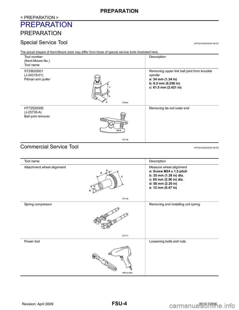
The actual shapes of Kent-Moore tools may differ from those of special service tools illustrated here.
Commercial Service ToolINFOID:0000000005148106
Tool number
(Kent-Moore No.)
Tool name Description
ST29020001
(J-24319-01)
Pitman arm puller Removing upper link ball joint from knuckle
spindle
a: 34 mm (1.34 in)
b: 6.5 mm (0.256 in)
c: 61.5 mm (2.421 in)
HT72520000
(J-25730-A)
Ball joint remover Removing tie-rod outer end
NT694
NT146
Tool name
Description
Attachment wheel alignment Measure wheel alignment
a: Screw M24 x 1.5 pitch
b: 35 mm (1.38 in) dia.
c: 65 mm (2.56 in) dia.
d: 56 mm (2.20 in)
e: 12 mm (0.47 in)
Spring compressor Removing and installing coil spring
Power tool Loosening bolts and nuts
NT148
NT717
PBIC0190E
Revision: April 20092010 QX56
Page 2209 of 4210
FSU-10
< ON-VEHICLE MAINTENANCE >
UPPER BALL JOINT AND LOWER BALL JOINT
UPPER BALL JOINT AND LOWER BALL JOINT
InspectionINFOID:0000000005148110
• Check the ball joint for excessive play. Replace the upper or lower link assembly if any of the followingexists:
- Ball joint stud is worn.
- Ball joint is hard to swing.
- Ball joint play in axial directions or end play is excessive.
Swinging Force
NOTE:
Before checking the axial forces and end play, turn the lower ball joint at least 10 revolutions so that the ball
joint is properly broken in.
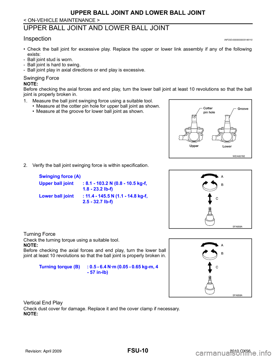
1. Measure the ball joint swinging force using a suitable tool.
• Measure at the cotter pin hole for upper ball joint as shown.
• Measure at the groove for lower ball joint as shown.
2. Verify the ball joint swinging force is within specification.
Turning Force
Check the turning torque using a suitable tool.
NOTE:
Before checking the axial forces and end play, turn the lower ball
joint at least 10 revolutions so that the ball joint is properly broken in.
Vertical End Play
Check dust cover for damage. Replace it and the cover clamp if necessary.
NOTE:
WEIA0076E
Swinging force (A)
Upper ball joint : 8.1 - 103.2 N (0.8 - 10.5 kg-f, 1.8 - 23.2 lb-f)
Lower ball joint : 11.4 - 145.5 N (1.1 - 14.8 kg-f, 2.5 - 32.7 lb-f)
SFA858A
Turning torque (B) : 0.5 - 6.4 N·m (0.05 - 0.65 kg-m, 4 - 57 in-lb)
SFA858A
Revision: April 20092010 QX56
Page 2212 of 4210
FRONT SUSPENSION ASSEMBLYFSU-13
< ON-VEHICLE REPAIR >
C
DF
G H
I
J
K L
M A
B
FSU
N
O P
ON-VEHICLE REPAIR
FRONT SUSPENSION ASSEMBLY
ComponentINFOID:0000000005148112
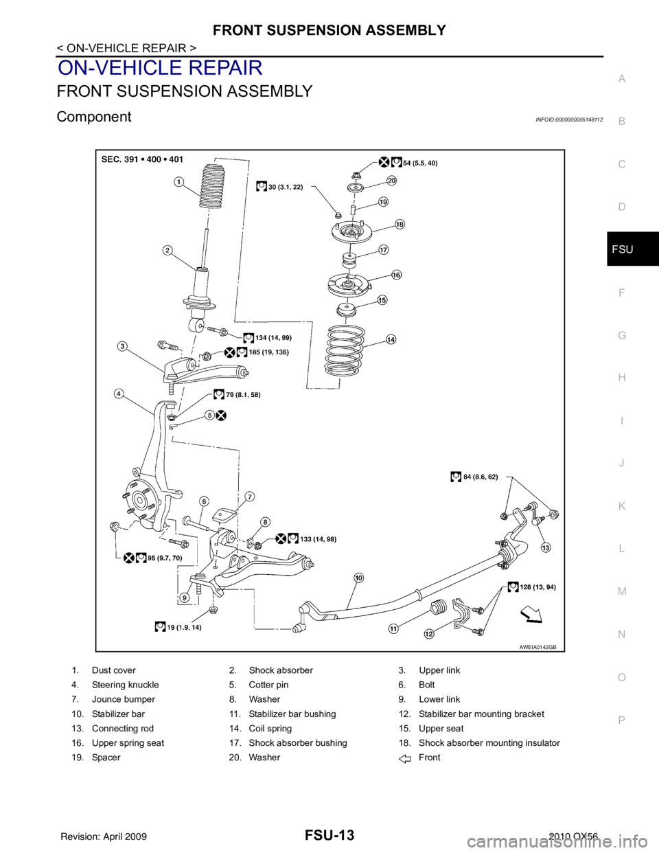
1. Dust cover 2. Shock absorber 3. Upper link
4. Steering knuckle 5. Cotter pin 6. Bolt
7. Jounce bumper 8. Washer 9. Lower link
10. Stabilizer bar 11. Stabilizer bar bushing 12. Stabilizer bar mounting bracket
13. Connecting rod 14. Coil spring 15. Upper seat
16. Upper spring seat 17. Shock absorber bushing 18. Shock absorber mounting insulator
19. Spacer 20. Washer Front
AWEIA0142GB
Revision: April 20092010 QX56
Page 2215 of 4210
FSU-16
< REMOVAL AND INSTALLATION >
UPPER LINK
UPPER LINK
Removal and InstallationINFOID:0000000005148115
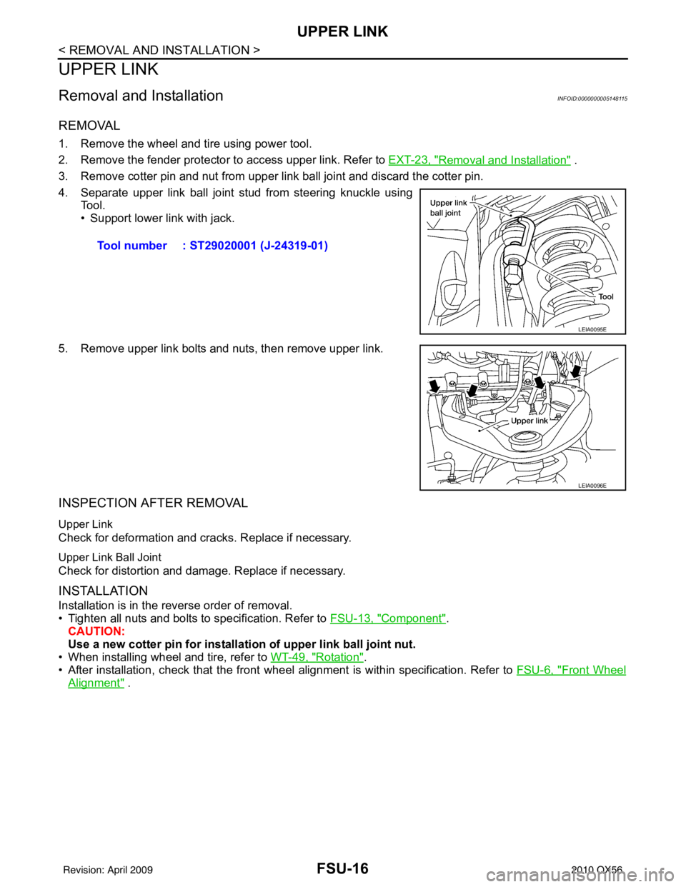
REMOVAL
1. Remove the wheel and tire using power tool.
2. Remove the fender protector to access upper link. Refer to EXT-23, "
Removal and Installation" .
3. Remove cotter pin and nut from upper link ball joint and discard the cotter pin.
4. Separate upper link ball joint stud from steering knuckle using Tool.
• Support lower link with jack.
5. Remove upper link bolts and nuts, then remove upper link.
INSPECTION AFTER REMOVAL
Upper Link
Check for deformation and cracks. Replace if necessary.
Upper Link Ball Joint
Check for distortion and damage. Replace if necessary.
INSTALLATION
Installation is in the reverse order of removal.
• Tighten all nuts and bolts to specification. Refer to FSU-13, "
Component".
CAUTION:
Use a new cotter pin for installation of upper link ball joint nut.
• When installing wheel and tire, refer to WT-49, "
Rotation".
• After installation, check that the front wheel alignment is within specification. Refer to FSU-6, "
Front Wheel
Alignment" .
Tool number : ST29020001 (J-24319-01)
LEIA0095E
LEIA0096E
Revision: April 20092010 QX56
Page 2217 of 4210
FSU-18
< REMOVAL AND INSTALLATION >
UPPER BALL JOINT AND LOWER BALL JOINT
UPPER BALL JOINT AND LOWER BALL JOINT
Removal and InstallationINFOID:0000000005148117
The ball joints are part of the upper and lower links. Refer to FSU-16, "Removal and Installation" (upper link),
FSU-17, "
Removal and Installation" (lower link).
Revision: April 20092010 QX56