2010 INFINITI QX56 TM-45
[x] Cancel search: TM-45Page 1050 of 4210
![INFINITI QX56 2010 Factory Service Manual DLK-216
< SYMPTOM DIAGNOSIS >[WITH INTELLIGENT KEY SYSTEM]
WARNING FUNCTION SYMPTOMS
WARNING FUNCTION SYMPTOMS
Symptom TableINFOID:0000000005147038
WARNING FUNCTION MALFUNCTION
NOTE:
• Before perfor](/manual-img/42/57032/w960_57032-1049.png "INFINITI QX56 2010 Factory Service Manual DLK-216
< SYMPTOM DIAGNOSIS >[WITH INTELLIGENT KEY SYSTEM]
WARNING FUNCTION SYMPTOMS
WARNING FUNCTION SYMPTOMS
Symptom TableINFOID:0000000005147038
WARNING FUNCTION MALFUNCTION
NOTE:
• Before perfor")
DLK-216
< SYMPTOM DIAGNOSIS >[WITH INTELLIGENT KEY SYSTEM]
WARNING FUNCTION SYMPTOMS
WARNING FUNCTION SYMPTOMS
Symptom TableINFOID:0000000005147038
WARNING FUNCTION MALFUNCTION
NOTE:
• Before performing the diagnosis in the following table, check “WORK FLOW”. Refer to
DLK-6, "
Work Flow".
• Check that vehicle is under the condition shown in “Conditions of vehicle” before starting diagnosis, and check each symptom.
• If the following “symptoms are detected, check systems shown in the “Diagnosis/service procedure” column
in this order.
Conditions of Vehicle (Operating Conditions)
Warning chime functions operating condition is extremely complicated, during operating confirmations, recon-
firm the list above twice in order to ensure proper operation.
Symptom Diagnosis/service procedure Reference
page
OFF position warn-
ing does not oper-
ate. For internal
1. Check ignition knob switch.
DLK-116
2. Check door switch. DLK-71
3. Check warning chime function.D L K - 111
4. Check Intermittent Incident. GI-38
For external1. Check ignition knob switch.
DLK-1162. Check door switch. DLK-71
3. Check Intelligent Key warning buzzer.DLK-95
4. Check Intermittent Incident. GI-38
P position warning does not operate.1. Check Park position switch.
TM-45
2. Check door switch.DLK-71
3. Check Intelligent Key warning buzzer.DLK-95
4. Check warning chime function.D L K - 111
5. Check combination meter display function.DLK-110
6. Check Intermittent Incident. GI-38
ACC warning does not operate1. Check ignition knob switch.
DLK-1162. Check warning chime function. D L K - 111
3. Check combination meter display function.DLK-110
4. Check Intermittent Incident. GI-38
Revision: April 20092010 QX56
Page 1814 of 4210
![INFINITI QX56 2010 Factory Service Manual ECM
EC-461
< ECU DIAGNOSIS > [VK56DE]
C
D
E
F
G H
I
J
K L
M A
EC
NP
OEVAP GROSS LEAK
P04550455—2×EC-254
EVAP VERY SML LEAK P04560456
×*42 ×EC-261
FUEL LEV SEN SLOSH P04600460—2×EC-269
FUEL LEV](/manual-img/42/57032/w960_57032-1813.png "INFINITI QX56 2010 Factory Service Manual ECM
EC-461
< ECU DIAGNOSIS > [VK56DE]
C
D
E
F
G H
I
J
K L
M A
EC
NP
OEVAP GROSS LEAK
P04550455—2×EC-254
EVAP VERY SML LEAK P04560456
×*42 ×EC-261
FUEL LEV SEN SLOSH P04600460—2×EC-269
FUEL LEV")
ECM
EC-461
< ECU DIAGNOSIS > [VK56DE]
C
D
E
F
G H
I
J
K L
M A
EC
NP
OEVAP GROSS LEAK
P04550455—2×EC-254
EVAP VERY SML LEAK P04560456
×*42 ×EC-261
FUEL LEV SEN SLOSH P04600460—2×EC-269
FUEL LEVEL SENSOR P04610461—2×EC-271
FUEL LEVL SEN/CIRC P04620462—2×EC-273
FUEL LEVL SEN/CIRC P04630463—2×EC-273
VEH SPEED SEN/CIRC*6P0500 0500—2×EC-275
ISC SYSTEM P05060506—2×EC-277
ISC SYSTEM P05070507—2×EC-279
PW ST P SEN/CIRC P05500550—2—EC-281
ECM BACK UP/CIRC P06030603—2×EC-284
ECM P06050605—1 or 2 × or — EC-286
ECM P06070607—1×EC-288
SENSOR POWER/CIRC P06430643—1×EC-289
TRANSMISSION CONT P07000700—1×TM-44
T/M RANGE SENSOR A P07050705—2×TM-45
FLUID TEMP SENSOR A P07100710—2×TM-73
INPUT SPEED SENSOR A P07170717—2×TM-48
OUTPUT SPEED SENSOR*6P0720 0720—2×TM-50
1GR INCORRECT RATION P07310731—2×TM-55
2GR INCORRECT RATION P07320732—2×TM-57
3GR INCORRECT RATION P07330733—2×TM-59
4GR INCORRECT RATION P07340734—2×TM-61
5GR INCORRECT RATION P07350735—2×TM-63
TORQUE CONVERTER P07400740—2×TM-65
TORQUE CONVERTER P07440744—2×TM-67
PC SOLENOID A P07450745—2×TM-69
P-N POS SW/CIRCUIT P08500850—2×EC-292
INTK TIM S/CIRC-B1 P11401140—2×EC-295
INTK TIM S/CIRC-B2 P11451145—2×EC-295
CLOSED LOOP-B1 P11481148—1×EC-299
CLOSED LOOP-B2 P11681168—1×EC-299
TCS C/U FUNCTN P12111211—2—EC-300
TCS/CIRC P12121212—2—EC-301
ENG OVER TEMP P12171217—1×EC-36
CTP LEARNING-B1 P12251225—2—EC-306
CTP LEARNING-B1 P12261226—2—EC-308
COLD START CONTROL P14211421—2×EC-310
BAT CURRENT SENSOR P15501550—2—EC-312
BAT CURRENT SENSOR P15511551—2—EC-316
BAT CURRENT SENSOR P15521552—2—EC-316
BAT CURRENT SENSOR P15531553—2—EC-320
Items
(CONSULT-IIl screen terms) DTC*
1
SRT code Trip
MILReference
page
CONSULT-IIl
GST*
2ECM*3
Revision: April 20092010 QX56
Page 1832 of 4210
![INFINITI QX56 2010 Factory Service Manual ENGINE CONTROL SYSTEM SYMPTOMSEC-479
< SYMPTOM DIAGNOSIS > [VK56DE]
C
D
E
F
G H
I
J
K L
M A
EC
NP
O
SYMPTOM
Reference
page
HARD/NO START/RESTART (EXCP. HA)
ENGINE STALL
HESITATION/SURGING/FLAT SPOT
S](/manual-img/42/57032/w960_57032-1831.png "INFINITI QX56 2010 Factory Service Manual ENGINE CONTROL SYSTEM SYMPTOMSEC-479
< SYMPTOM DIAGNOSIS > [VK56DE]
C
D
E
F
G H
I
J
K L
M A
EC
NP
O
SYMPTOM
Reference
page
HARD/NO START/RESTART (EXCP. HA)
ENGINE STALL
HESITATION/SURGING/FLAT SPOT
S")
ENGINE CONTROL SYSTEM SYMPTOMSEC-479
< SYMPTOM DIAGNOSIS > [VK56DE]
C
D
E
F
G H
I
J
K L
M A
EC
NP
O
SYMPTOM
Reference
page
HARD/NO START/RESTART (EXCP. HA)
ENGINE STALL
HESITATION/SURGING/FLAT SPOT
SPARK KNOCK/DETONATION
LACK OF POWER/POOR ACCELERATION
HIGH IDLE/LOW IDLE
ROUGH IDLE/HUNTING
IDLING VIBRATION
SLOW/NO RETURN TO IDLE
OVERHEATS/WATER TEMPERATURE HIGH
EXCESSIVE FUEL CONSUMPTION
EXCESSIVE OIL CONSUMPTION
BATTERY DEAD (UNDER CHARGE)
Warranty symptom code AA AB AC AD AE AF AG AH AJ AK AL AM HA
Fuel Fuel tank 5
5 FL-11
Fuel piping
5 5 5 5 55FL-6
Va p o r l o c k —
Valve deposit 5 555 55 5—
Poor fuel (Heavy weight gasoline,
Low octane) —
Air Air duct
55555 5 EM-25
Air cleaner
EM-25
Air leakage from air duct
(Mass air flow sensor — electric
throttle control actuator)
5555 EM-25
Electric throttle control actuator
EM-26
Air leakage from intake manifold/
Collector/GasketEM-26
Cranking Battery
111111
11
PG-74
Generator circuit
CHG-6
Starter circuit3 STR-8
Signal plate6 EM-45
Park/Neutral position (PNP) sig-
nal4
TM-45
Engine Cylinder head
55555 55 5 EM-68
Cylinder head gasket 4 3
Cylinder block
66666 66 64
EM-83
Piston
Piston ring
Connecting rod
Bearing
Crankshaft
Va l v e
mecha-
nism Timing chain
55555 55 5EM-45
Camshaft
EM-53
Intake valve timing controlEM-53
Intake valve
3EM-68
Exhaust valve
Revision: April 20092010 QX56
Page 3466 of 4210
![INFINITI QX56 2010 Factory Service Manual INTELLIGENT KEY SYSTEM/ENGINE START FUNCTION SYMPTOMS
SEC-115
< SYMPTOM DIAGNOSIS > [WITH INTELLIGENT KEY SYSTEM]
C
D
E
F
G H
I
J
L
M A
B
SEC
N
O P
SYMPTOM DIAGNOSIS
INTELLIGENT KEY SYSTEM/ENGIN E STA](/manual-img/42/57032/w960_57032-3465.png "INFINITI QX56 2010 Factory Service Manual INTELLIGENT KEY SYSTEM/ENGINE START FUNCTION SYMPTOMS
SEC-115
< SYMPTOM DIAGNOSIS > [WITH INTELLIGENT KEY SYSTEM]
C
D
E
F
G H
I
J
L
M A
B
SEC
N
O P
SYMPTOM DIAGNOSIS
INTELLIGENT KEY SYSTEM/ENGIN E STA")
INTELLIGENT KEY SYSTEM/ENGINE START FUNCTION SYMPTOMS
SEC-115
< SYMPTOM DIAGNOSIS > [WITH INTELLIGENT KEY SYSTEM]
C
D
E
F
G H
I
J
L
M A
B
SEC
N
O P
SYMPTOM DIAGNOSIS
INTELLIGENT KEY SYSTEM/ENGIN E START FUNCTION SYMPTOMS
Symptom TableINFOID:0000000005147148
NOTE:
• Before performing the diagnosis in the following table, check “ SEC-4, "
Work Flow"”.
• Check that vehicle is under the condition shown in “Conditions of vehicle” before starting diagnosis, and check each symptom.
• Engine cranking is enabled when the shift lever is in the "Park" position, and in the "Neutral" position only if the brake pedal is depressed.
• If the following symptoms are detec ted, check systems shown in the “Diagnosis/service procedure” column
in this order.
CONDITIONS OF VEHICLE (OPERATING CONDITIONS)
• Engine start function is ON when setting on CONSULT-III.
• Mechanical key is not inserted in key cylinder.
• One or more of Intelligent Keys with registered Intelligent Key ID is in the vehicle.
Symptom Diagnosis/service procedureReference
page
Ignition switch does not turn on with Intelligent Key.
[LCD displays "KEY DETECTED"] 1. Check steering lock solenoid.
DLK-99
2. Replace Intelligent Key unit.SEC-120
Ignition switch does not turn on with Intelligent Key.
[LCD does not display "PUSH" with arrow toward key
cylinder] 1. Check Intelligent Key unit power supply and ground circuit.
DLK-682. Check ignition knob switch.DLK-116
3. Check key switch (BCM input).DLK-115
4. Check key switch (Intelligent Key unit input).DLK-113
5. Replace Intelligent Key unit.SEC-120
Ignition switch does not turn on with Intelligent Key.
[LCD displays " NO KEY"] 1a. Check center console area antenna (rear).
DLK-60
1b. Check luggage area antenna.DLK-62
1c. Check center console area antenna (front).DLK-64
1d. Check overhead console area antenna.DLK-68
2. Replace Intelligent Key unit.SEC-120
Ignition switch does not turn on with mechanical key1. Check key switch (BCM input).
DLK-1152. Check key switch (Intelligent Key unit input).DLK-113
Engine cannot be cranked with transmission in "Park"
or in "Neutral" position with brake pedal depressed.1. Check transmission signal.
TM-45
2. Check stop lamp switch.EXL-91
Revision: April 20092010 QX56
Page 3517 of 4210
SN
SONAR SYSTEM SYMPTOMSSN-45
< SYMPTOM DIAGNOSIS >
C
DE
F
G H
I
J
K L
M B A
O P
SYMPTOM DIAGNOSIS
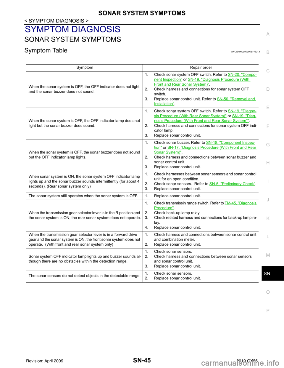
SONAR SYSTEM SYMPTOMS
Symptom TableINFOID:0000000005146213
Symptom Repair order
When the sonar system is OFF, the OFF indicator does not light
and the sonar buzzer does not sound. 1. Check sonar system OFF switch. Refer to
SN-20, "
Compo-
nent Inspection" or SN-19, "Diagnosis Procedure (With
Front and Rear Sonar System)".
2. Check harness and connections for sonar system OFF
switch.
3. Replace sonar control unit. Refer to SN-50, "
Removal and
Installation".
When the sonar system is OFF, the OFF indicator lamp does not
light but the sonar buzzer does sound. 1. Check sonar system OFF switch. Refer to
SN-19, "
Diagno-
sis Procedure (With Rear Sonar System)" or SN-19, "Diag-
nosis Procedure (With Front and Rear Sonar System)".
2. Check harness and connections for sonar system OFF indi- cator lamp.
3. Replace sonar control unit.
When the sonar system is OFF, the sonar buzzer does not sound
but the OFF indicator lamp lights. 1. Check sonar buzzer. Refer to
SN-18, "
Component Inspec-
tion" or SN-17, "Diagnosis Procedure (With Front and Rear
Sonar System)".
2. Check harness and connections between sonar buzzer and sonar control unit.
3. Replace sonar control unit.
When sonar system is ON, the sonar system OFF indicator lamp
lights up and the sonar buzzer sounds intermittently (for about 4
seconds). (Rear sonar system only) 1. Check harnesses between sonar sensors and sonar control
unit for an open condition.
2. Check sonar sensors. Refer to SN-5, "
Preliminary Check".
3. Replace sonar control unit.
The sonar system still operates when the sonar system is OFF. 1. Replace sonar control unit.
When the transmission gear selector lever is in the R position and
the sonar system is ON, the rear sonar system does not operate. 1. Check transmissin range switch. Refer to
TM-45, "
Diagnosis
Procedure".
2. Check back-up lamp relay.
3. Check related harness and connections for back-up lamp re- lay.
4. Replace sonar control unit.
When the transmission gear selector lever is in a forward drive
gear and the sonar system is ON, the front sonar system does not
operate. (With front and rear sonar system only) 1. Check harness and connections between sonar control unit
and combination meter.
2. Replace sonar control unit.
Sonar system OFF indicator lamp lights up and buzzer sounds al-
though there are no obstacles within the detection range. 1. Check sonar sensors.
2. Check harness and connections between sonar sensors
and sonar control unit.
3. Replace sonar control unit.
The sonar sensors do not detect objects in the detectable range. 1. Check sonar sensors.
2. Replace sonar control unit.
Revision: April 20092010 QX56
Page 3727 of 4210
TM-32
< FUNCTION DIAGNOSIS >
DIAGNOSIS SYSTEM (TCM)
DIAGNOSIS SYSTEM (TCM)
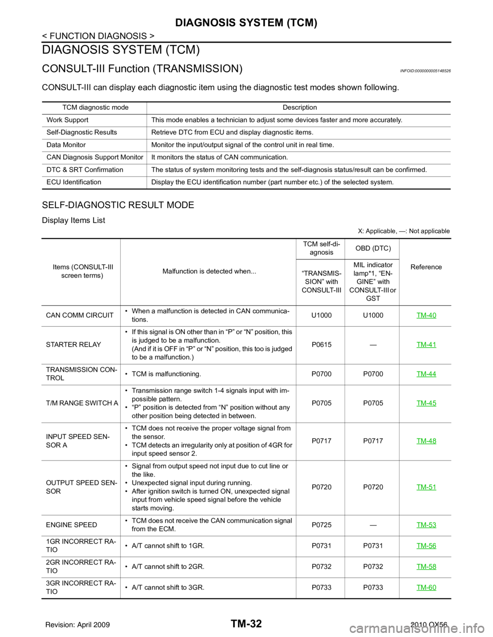
CONSULT-III Function (TRANSMISSION)INFOID:0000000005148526
CONSULT-III can display each diagnostic item us ing the diagnostic test modes shown following.
SELF-DIAGNOSTIC RESULT MODE
Display Items List
X: Applicable, —: Not applicable
TCM diagnostic mode Description
Work Support This mode enables a technician to adjust some devices faster and more accurately.
Self-Diagnostic Results Retrieve DTC from ECU and display diagnostic items.
Data Monitor Monitor the input/output signal of the control unit in real time.
CAN Diagnosis Support Monitor It monitors the status of CAN communication.
DTC & SRT Confirmation The status of system monitoring tests and the self-diagnosis status/result can be confirmed.
ECU Identification Display the ECU identification number (part number etc.) of the selected system.
Items (CONSULT-III
screen terms) Malfunction is detected when... TCM self-di-
agnosis OBD (DTC)
Reference
“TRANSMIS-
SION” with
CONSULT-III MIL indicator
lamp*1, “EN-
GINE” with
CONSULT-III or
GST
CAN COMM CIRCUIT • When a malfunction is detected in CAN communica-
tions. U1000 U1000
TM-40
STARTER RELAY• If this signal is ON other than in “P” or “N” position, this
is judged to be a malfunction.
(And if it is OFF in “P” or “N” position, this too is judged
to be a malfunction.) P0615
—TM-41
TRANSMISSION CON-
TROL • TCM is malfunctioning.
P0700 P0700TM-44
T/M RANGE SWITCH A• Transmission range switch 1-4 signals input with im-
possible pattern.
• “P” position is detected from “N” position without any other position being detected in between. P0705 P0705
TM-45
INPUT SPEED SEN-
SOR A• TCM does not receive the proper voltage signal from
the sensor.
• TCM detects an irregularity only at position of 4GR for input speed sensor 2. P0717 P0717
TM-48
OUTPUT SPEED SEN-
SOR• Signal from output speed not input due to cut line or
the like.
• Unexpected signal input during running.
• After ignition switch is turned ON, unexpected signal input from vehicle speed signal before the vehicle
starts moving. P0720 P0720
TM-51
ENGINE SPEED• TCM does not receive the CAN communication signal
from the ECM. P0725
—TM-53
1GR INCORRECT RA-
TIO • A/T cannot shift to 1GR.
P0731 P0731TM-56
2GR INCORRECT RA-
TIO• A/T cannot shift to 2GR.
P0732 P0732TM-58
3GR INCORRECT RA-
TIO• A/T cannot shift to 3GR.
P0733 P0733TM-60
Revision: April 20092010 QX56
Page 3733 of 4210
TM-38
< FUNCTION DIAGNOSIS >
DIAGNOSIS SYSTEM (TCM)
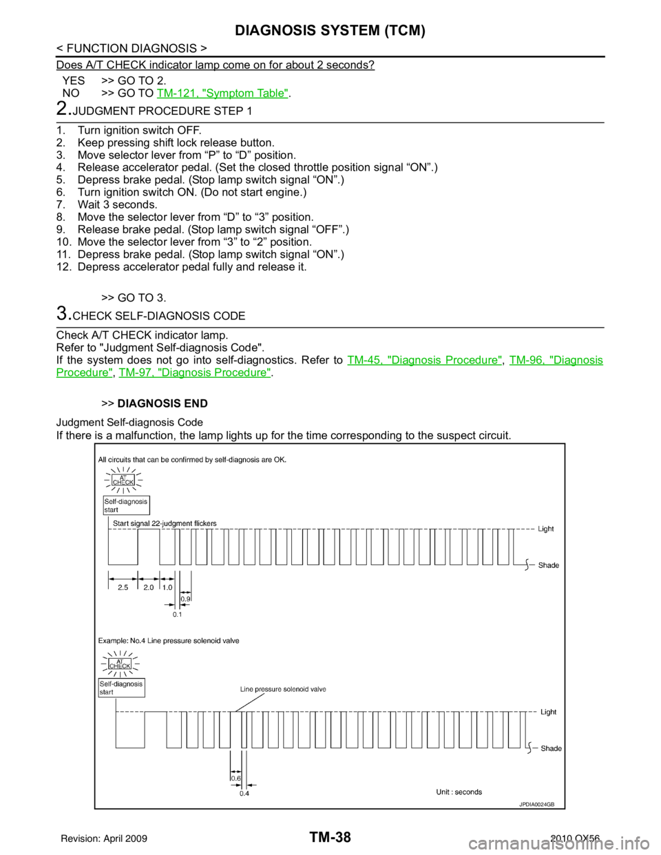
Does A/T CHECK indicator lamp come on for about 2 seconds?
YES >> GO TO 2.
NO >> GO TO TM-121, "
Symptom Table".
2.JUDGMENT PROCEDURE STEP 1
1. Turn ignition switch OFF.
2. Keep pressing shift lock release button.
3. Move selector lever from “P” to “D” position.
4. Release accelerator pedal. (Set the closed throttle position signal “ON”.)
5. Depress brake pedal. (Stop lamp switch signal “ON”.)
6. Turn ignition switch ON. (Do not start engine.)
7. Wait 3 seconds.
8. Move the selector lever from “D” to “3” position.
9. Release brake pedal. (Stop lamp switch signal “OFF”.)
10. Move the selector lever from “3” to “2” position.
11. Depress brake pedal. (Stop lamp switch signal “ON”.)
12. Depress accelerator pedal fully and release it.
>> GO TO 3.
3.CHECK SELF-DIAGNOSIS CODE
Check A/T CHECK indicator lamp.
Refer to "Judgment Self-diagnosis Code".
If the system does not go into self-diagnostics. Refer to TM-45, "
Diagnosis Procedure", TM-96, "Diagnosis
Procedure", TM-97, "Diagnosis Procedure".
>> DIAGNOSIS END
Judgment Self-diagnosis Code
If there is a malfunction, the lamp lights up for the time corresponding to the suspect circuit.
JPDIA0024GB
Revision: April 20092010 QX56
Page 3734 of 4210
DIAGNOSIS SYSTEM (TCM)TM-39
< FUNCTION DIAGNOSIS >
CEF
G H
I
J
K L
M A
B
TM
N
O P
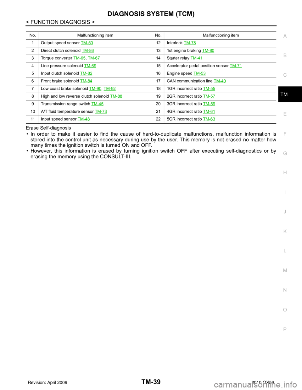
Erase Self-diagnosis
• In order to make it easier to find the cause of
hard-to-duplicate malfunctions, malfunction information is
stored into the control unit as necessary during use by the user. This memory is not erased no matter how
many times the ignition switch is turned ON and OFF.
• However, this information is erased by turning ignition switch OFF after executing self-diagnostics or by erasing the memory using the CONSULT-III.
No. Malfunctioning item No.Malfunctioning item
1 Output speed sensor TM-50
12 Interlock TM-78
2 Direct clutch solenoid TM-8613 1st engine braking TM-80
3 Torque converter TM-65, TM-6714 Starter relay TM-41
4 Line pressure solenoid TM-6915 Accelerator pedal position sensor TM-71
5 Input clutch solenoid TM-8216 Engine speed TM-53
6 Front brake solenoid TM-8417 CAN communication line TM-40
7 Low coast brake solenoid TM-90, TM-9218 1GR incorrect ratio TM-55
8 High and low reverse clutch solenoid TM-8819 2GR incorrect ratio TM-57
9 Transmission range switch TM-4520 3GR incorrect ratio TM-59
10 A/T fluid temperature sensor TM-7321 4GR incorrect ratio TM-61
11 Input speed sensor TM-4822 5GR incorrect ratio TM-63
Revision: April 20092010 QX56