2010 INFINITI QX56 cooling
[x] Cancel search: coolingPage 2329 of 4210

LOW-PRESSURE PIPEHA-37
< ON-VEHICLE REPAIR >
C
DE
F
G H
J
K L
M A
B
HA
N
O P
LOW-PRESSURE PIPE
Removal and Installation for Low-Pressure PipeINFOID:0000000005147656
REMOVAL
1. Discharge the refrigerant. Refer to HA-20, "HFC-134a (R-134a) Service Procedure".
2. Remove the cowl top and the cowl top extension. Refer to EXT-18, "
Removal and Installation".
3. Remove the low-pressure pipe. CAUTION:
Cap or wrap the joint of the pipes with suitable material such as viny l tape to avoid the entry of air.
INSTALLATION
Installation is in the reverse order of removal.
Refer to HA-29, "
Component".
CAUTION:
• Replace the O-ring of the high/low-pressure pipe with a new one, then apply compressor oil to it
when installing it.
• After charging refrigerant, check for leaks.
Removal and Installation for Rear High- and Low-Pressure A/C and Heater Core Pipes
INFOID:0000000005147657
REMOVAL
1. Discharge the refrigerant from the A/C system. Refer to HA-20, "HFC-134a (R-134a) Service Procedure".
2. Drain the coolant from the engine cooling system. Refer to CO-11, "
Changing Engine Coolant".
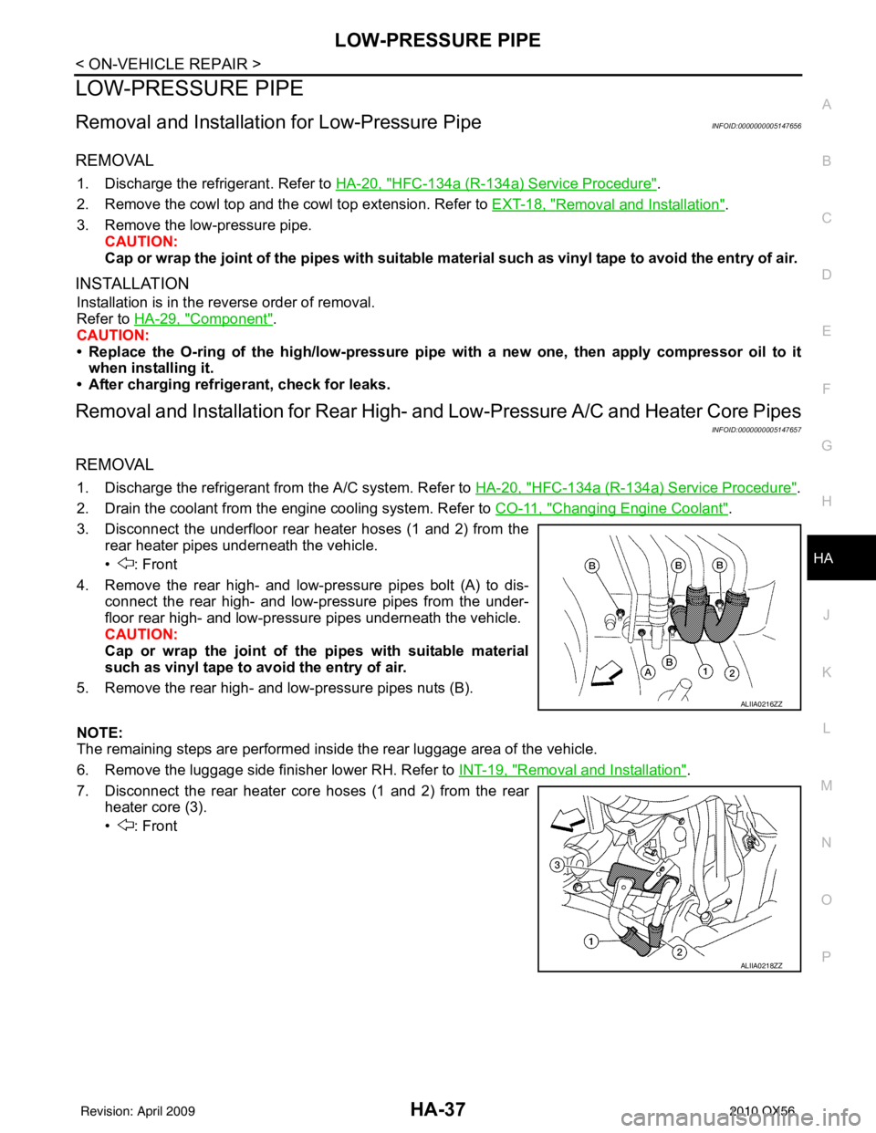
3. Disconnect the underfloor rear heater hoses (1 and 2) from the rear heater pipes underneath the vehicle.
• : Front
4. Remove the rear high- and low-pressure pipes bolt (A) to dis- connect the rear high- and low-pressure pipes from the under-
floor rear high- and low-pressure pipes underneath the vehicle.
CAUTION:
Cap or wrap the joint of the pipes with suitable material
such as vinyl tape to avo id the entry of air.
5. Remove the rear high- and low-pressure pipes nuts (B).
NOTE:
The remaining steps are performed inside the rear luggage area of the vehicle.
6. Remove the luggage side finisher lower RH. Refer to INT-19, "
Removal and Installation".
7. Disconnect the rear heater core hoses (1 and 2) from the rear heater core (3).
• : Front
ALIIA0216ZZ
ALIIA0218ZZ
Revision: April 20092010 QX56
Page 2330 of 4210

HA-38
< ON-VEHICLE REPAIR >
LOW-PRESSURE PIPE
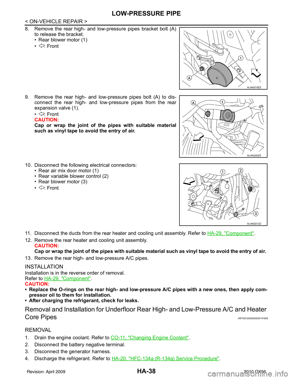
8. Remove the rear high- and low-pressure pipes bracket bolt (A)to release the bracket.
• Rear blower motor (1)
• : Front
9. Remove the rear high- and low-pressure pipes bolt (A) to dis- connect the rear high- and low-pressure pipes from the rear
expansion valve (1).
• : Front
CAUTION:
Cap or wrap the joint of the pipes with suitable material
such as vinyl tape to avoid the entry of air.
10. Disconnect the following electrical connectors: • Rear air mix door motor (1)
• Rear variable blower control (2)
• Rear blower motor (3)
• : Front
11. Disconnect the ducts from the rear heater and cooling unit assembly. Refer to HA-29, "
Component".
12. Remove the rear heater and cooling unit assembly. CAUTION:
Cap or wrap the joint of the pipes with suitable material such as viny l tape to avoid the entry of air.
13. Remove the rear high- and low-pressure A/C pipes.
INSTALLATION
Installation is in the reverse order of removal.
Refer to HA-29, "
Component".
CAUTION:
• Replace the O-rings on the rear high- and low-pr essure A/C pipes with a new ones, then apply com-
pressor oil to them for installation.
• After charging the refrigerant, check for leaks.
Removal and Installati on for Underfloor Rear High- and Low-Pressure A/C and Heater
Core Pipes
INFOID:0000000005147658
REMOVAL
1. Drain the engine coolant. Refer to CO-11, "Changing Engine Coolant".
2. Disconnect the battery negative terminal.
3. Disconnect the generator harness.
4. Discharge the refrigerant. Refer to HA-20, "
HFC-134a (R-134a) Service Procedure".
ALIIA0219ZZ
ALIIA0220ZZ
ALIIA0221ZZ
Revision: April 20092010 QX56
Page 2333 of 4210

HIGH-PRESSURE PIPEHA-41
< ON-VEHICLE REPAIR >
C
DE
F
G H
J
K L
M A
B
HA
N
O P
HIGH-PRESSURE PIPE
Removal and Installation for High-Pressure PipeINFOID:0000000005147660
REMOVAL
1. Remove the cowl top extension. Refer to EXT-18, "Removal and Installation".
2. Disconnect the battery negative terminal and positive battery terminal.
3. Reposition the IPDM E/R aside.
4. Remove the front right wheel and tire assembly. Refer to WT-49, "
Rotation".
5. Position aside the front floor insulator.
6. Discharge the refrigerant. Refer to HA-20, "
HFC-134a (R-134a) Service Procedure".
7. Remove the low pressure pipe. Refer to HA-37, "
Removal and Installation for Low-Pressure Pipe".
8. Remove the high-pressure pipe. CAUTION:
Cap or wrap the joint of the pipe with suitable mate rial such as vinyl tape to avoid the entry of air.
INSTALLATION
Installation is in the reverse order of removal.
Refer to HA-29, "
Component".
CAUTION:
• Replace the O-ring of the high-pressure pipe with a new one, then apply compressor oil to it when
installing it.
• After charging refrigerant, check for leaks.
Removal and Installation for Rear High- and Low-Pressure A/C and Heater Core Pipes
INFOID:0000000005147661
REMOVAL
1. Discharge the refrigerant from the A/C system. Refer to HA-20, "HFC-134a (R-134a) Service Procedure".
2. Drain the coolant from the engine cooling system. Refer to CO-11, "
Changing Engine Coolant".
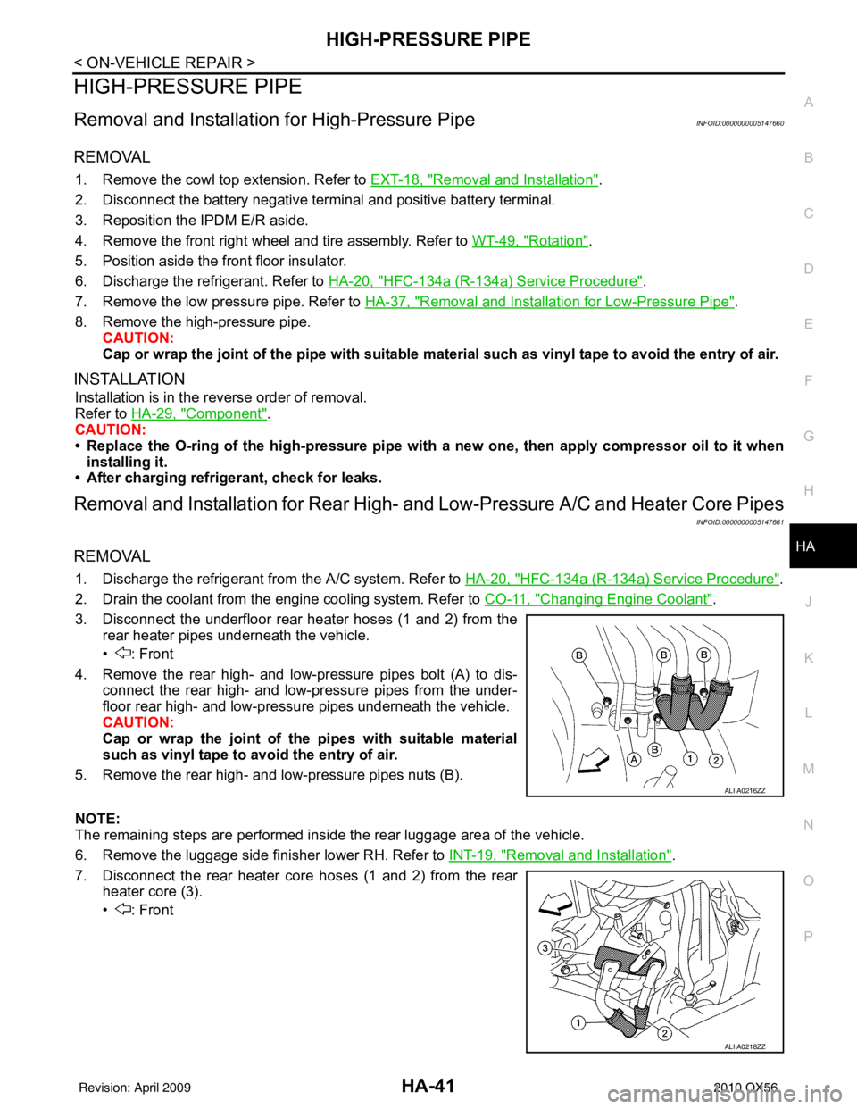
3. Disconnect the underfloor rear heater hoses (1 and 2) from the rear heater pipes underneath the vehicle.
• : Front
4. Remove the rear high- and low-pressure pipes bolt (A) to dis- connect the rear high- and low-pressure pipes from the under-
floor rear high- and low-pressure pipes underneath the vehicle.
CAUTION:
Cap or wrap the joint of the pipes with suitable material
such as vinyl tape to avo id the entry of air.
5. Remove the rear high- and low-pressure pipes nuts (B).
NOTE:
The remaining steps are performed inside the rear luggage area of the vehicle.
6. Remove the luggage side finisher lower RH. Refer to INT-19, "
Removal and Installation".
7. Disconnect the rear heater core hoses (1 and 2) from the rear heater core (3).
• : Front
ALIIA0216ZZ
ALIIA0218ZZ
Revision: April 20092010 QX56
Page 2334 of 4210

HA-42
< ON-VEHICLE REPAIR >
HIGH-PRESSURE PIPE
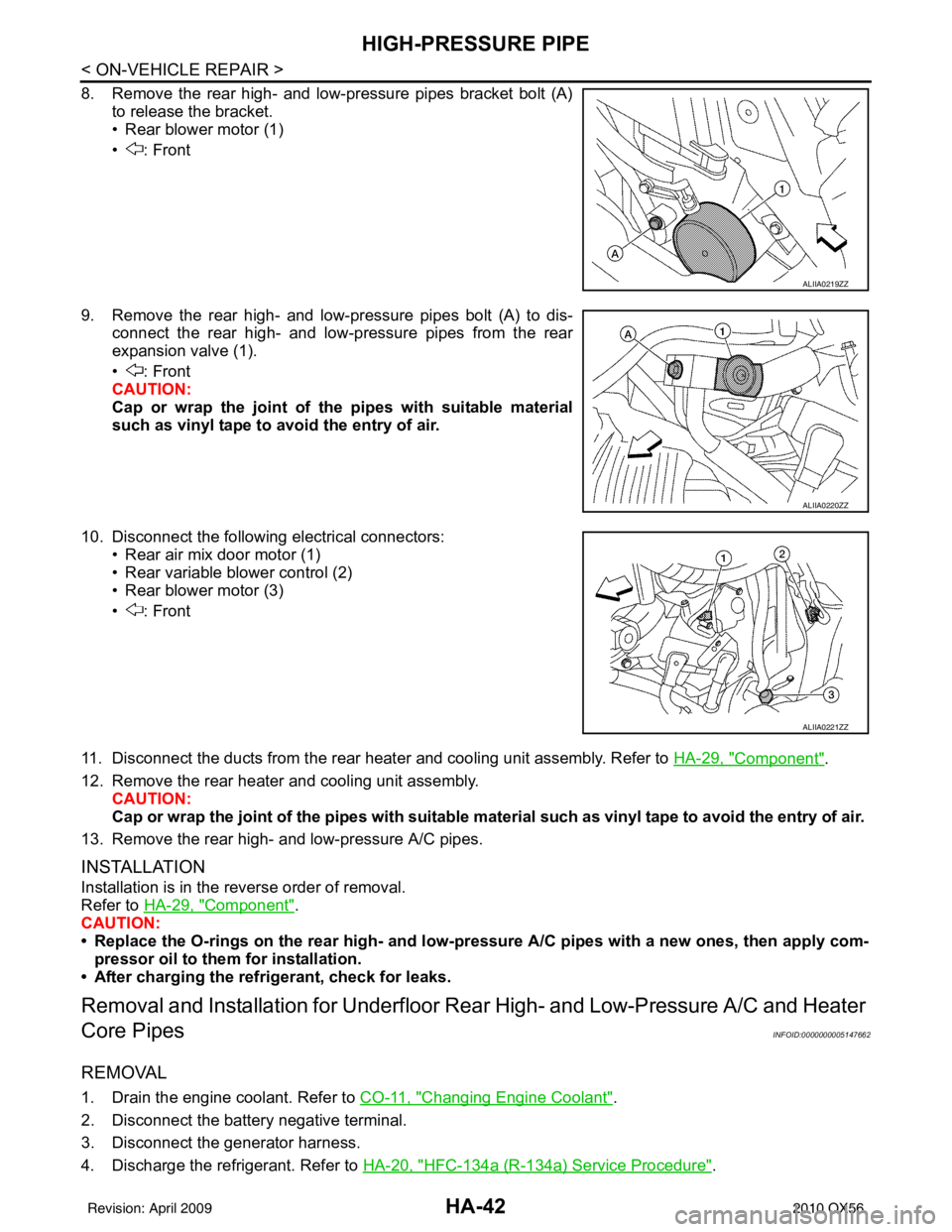
8. Remove the rear high- and low-pressure pipes bracket bolt (A)to release the bracket.
• Rear blower motor (1)
• : Front
9. Remove the rear high- and low-pressure pipes bolt (A) to dis- connect the rear high- and low-pressure pipes from the rear
expansion valve (1).
• : Front
CAUTION:
Cap or wrap the joint of the pipes with suitable material
such as vinyl tape to avoid the entry of air.
10. Disconnect the following electrical connectors: • Rear air mix door motor (1)
• Rear variable blower control (2)
• Rear blower motor (3)
• : Front
11. Disconnect the ducts from the rear heater and cooling unit assembly. Refer to HA-29, "
Component".
12. Remove the rear heater and cooling unit assembly. CAUTION:
Cap or wrap the joint of the pipes with suitable material such as viny l tape to avoid the entry of air.
13. Remove the rear high- and low-pressure A/C pipes.
INSTALLATION
Installation is in the reverse order of removal.
Refer to HA-29, "
Component".
CAUTION:
• Replace the O-rings on the rear high- and low-pr essure A/C pipes with a new ones, then apply com-
pressor oil to them for installation.
• After charging the refrigerant, check for leaks.
Removal and Installati on for Underfloor Rear High- and Low-Pressure A/C and Heater
Core Pipes
INFOID:0000000005147662
REMOVAL
1. Drain the engine coolant. Refer to CO-11, "Changing Engine Coolant".
2. Disconnect the battery negative terminal.
3. Disconnect the generator harness.
4. Discharge the refrigerant. Refer to HA-20, "
HFC-134a (R-134a) Service Procedure".
ALIIA0219ZZ
ALIIA0220ZZ
ALIIA0221ZZ
Revision: April 20092010 QX56
Page 2342 of 4210

HAC-2
Rear Air Control Component Function Check ........58
Air Mix Door Motor (Rear) Diagnosis Procedure ....59
Mode Door Motor (Rear) Diagnosis Procedure ......63
MAGNET CLUTCH ............................................68
System Description .............................................. ...68
Magnet Clutch Component Function Check ........ ...68
Magnet Clutch Diagnosis Procedure ................... ...68
WATER VALVE CIRCUIT ..................................73
Description ........................................................... ...73
Water Valve Diagnosis Procedure ..........................73
AMBIENT SENSOR ...........................................75
Component Description ....................................... ...75
Ambient Sensor Diagnosis Procedure ....................75
Ambient Sensor Component Inspection .................76
IN-VEHICLE SENSOR .......................................78
Component Description ....................................... ...78
In-Vehicle Sensor Diagnosis Procedure .................78
In-Vehicle Sensor Component Inspection ..............80
OPTICAL SENSOR ...........................................81
Component Description ..........................................81
Optical Sensor Diagnosis Procedure ......................81
INTAKE SENSOR ..............................................83
System Description .............................................. ...83
Intake Sensor Diagnosis Procedure .......................83
Intake Sensor Component Inspection ................. ...84
POWER SUPPLY AND GROUND CIRCUIT
FOR CONTROLLER ..........................................
86
Component Description ....................................... ...86
A/C Auto Amp. Component Function Check ..........86
A/C Auto Amp Power and Ground Diagnosis Pro-
cedure .................................................................. ...
87
ECU DIAGNOSIS .......................................89
AIR CONDITIONER CONTROL ..................... ...89
A/C Auto Amp. Terminals Reference Values ..........89
Wiring Diagram .................................................... ...91
SYMPTOM DIAGNOSIS ...........................107
AIR CONDITIONER CONTROL ..................... ..107
Symptom Matrix Chart ........................................ .107
INSUFFICIENT COOLING ................................108
Component Function Check ................................ .108
Diagnostic Work Flow ...........................................109
Performance Chart ................................................111
Trouble Diagnoses for Abnormal Pressure ...........112
INSUFFICIENT HEATING ................................116
Component Function Check .................................116
NOISE ...............................................................118
Component Function Check ................................ .118
MEMORY FUNCTION DOES NOT OPERATE ..120
Memory Function Check ...................................... .120
PRECAUTION ...........................................121
PRECAUTIONS .............................................. ..121
Precaution for Supplemental Restraint System
(SRS) "AIR BAG" and "SEAT BELT PRE-TEN-
SIONER" .............................................................. .
121
Working with HFC-134a (R-134a) ........................ .121
Precaution for Service Equipment ........................122
Revision: April 20092010 QX56
Page 2350 of 4210
![INFINITI QX56 2010 Factory Service Manual HAC-10
< FUNCTION DIAGNOSIS >[AUTOMATIC AIR CONDITIONER]
FUNCTION INFORMATION
Defroster door motor is malfunctioning. Go to Trouble Diagnosis Procedure for Defroster Door Motor.
HAC-43
Front blower mo INFINITI QX56 2010 Factory Service Manual HAC-10
< FUNCTION DIAGNOSIS >[AUTOMATIC AIR CONDITIONER]
FUNCTION INFORMATION
Defroster door motor is malfunctioning. Go to Trouble Diagnosis Procedure for Defroster Door Motor.
HAC-43
Front blower mo](/manual-img/42/57032/w960_57032-2349.png)
HAC-10
< FUNCTION DIAGNOSIS >[AUTOMATIC AIR CONDITIONER]
FUNCTION INFORMATION
Defroster door motor is malfunctioning. Go to Trouble Diagnosis Procedure for Defroster Door Motor.
HAC-43
Front blower motor operation is malfunction-
ing.Go to Trouble Diagnosis Procedure for Front Blower Motor.
HAC-48
Rear blower motor operation is malfunction-
ing.Go to Trouble Diagnosis Procedure for Rear Blower Motor.
HAC-53
Rear air discharge outlet does not change. Go to Trouble Diagnosis Procedure for Mode Door Motor (rear). HAC-58
Rear air temperature does not change. Go to Trouble Diagnosis Procedure for Air Mix Door Motor (rear).HAC-58
Magnet clutch does not engage.Go to Trouble Diagnosis Procedure for Magnet Clutch. HAC-68
Insufficient coolingGo to Trouble Diagnosis Procedure for Insufficient Cooling. HAC-108
Insufficient heatingGo to Trouble Diagnosis Procedure for Insufficient Heating. HAC-116
NoiseGo to Trouble Diagnosis Procedure for Noise. HAC-118
Self-diagnosis cannot be performed. Go to Trouble Diagnosis Procedure for Self-diagnosis. HAC-86
Memory function does not operate.Go to Trouble Diagnosis Procedure for Memory Function. HAC-120
SymptomReference Page
Revision: April 20092010 QX56
Page 2366 of 4210
![INFINITI QX56 2010 Factory Service Manual HAC-26
< COMPONENT DIAGNOSIS >[AUTOMATIC AIR CONDITIONER]
MODE DOOR MOTOR
The mode door motor (front) is attached to the heater & cooling unit
assembly. It rotates so that air is discharged from the o INFINITI QX56 2010 Factory Service Manual HAC-26
< COMPONENT DIAGNOSIS >[AUTOMATIC AIR CONDITIONER]
MODE DOOR MOTOR
The mode door motor (front) is attached to the heater & cooling unit
assembly. It rotates so that air is discharged from the o](/manual-img/42/57032/w960_57032-2365.png)
HAC-26
< COMPONENT DIAGNOSIS >[AUTOMATIC AIR CONDITIONER]
MODE DOOR MOTOR
The mode door motor (front) is attached to the heater & cooling unit
assembly. It rotates so that air is discharged from the outlet as indi-
cated by the A/C auto amp. Motor rotation is conveyed to a link
which activates the mode door.
Mode Door Motor (Front)
Component Function CheckINFOID:0000000005147688
INSPECTION FLOW
1.CONFIRM SYMPTOM BY PERFORMING OP ERATIONAL CHECK - DISCHARGE AIR
1. Press mode switch four times and then press the (DEF) switch. Each position indicator should change shape (on display).
2. Confirm that discharge air comes out according to the air distribution table. Refer to HAC-16, "
Discharge
Air Flow (Front)".
NOTE:
Confirm that the compressor clutch is engaged (visual inspection) and intake door position is at FRESH
when DEF ( ) or D/F ( ) is selected.
Is the inspection result normal?
YES >> Inspection End.
NO >> Go to diagnosis procedure. Refer to HAC-26, "
Mode Door Motor (Front) Diagnosis Procedure".
Mode Door Motor (Front) Diagnosis ProcedureINFOID:0000000005147689
Regarding Wiring Diagram information, refer to HAC-91, "Wiring Diagram".
SYMPTOM:• Air outlet does not change.
• Mode door motor does not operate normally.
1.CHECK A/C AUTO AMP. FOR POWER AND GROUND
1. Turn ignition switch ON.
2. Press the mode switch to the B/L ( ) mode.
3. Check voltage between A/C auto amp. harness connector M49 terminal 19 and terminal 20 while pressing the mode switch to
the floor ( ) mode.
Is the inspection result normal?
YES >> GO TO 3.
NO >> GO TO 2.
2.CHECK MODE DOOR MOTOR CIRCUITS FOR SHORT TO GROUND
WJIA0587E
Connector Te r m i n a l s
Condition Voltage
(Approx.)
(+) (-)
A/C auto amp.: M49 20
19Press
mode
switch Battery
voltage
AWIIA0095ZZ
Revision: April 20092010 QX56
Page 2371 of 4210
![INFINITI QX56 2010 Factory Service Manual AIR MIX DOOR MOTORHAC-31
< COMPONENT DIAGNOSIS > [AUTOMATIC AIR CONDITIONER]
C
D
E
F
G H
J
K L
M A
B
HAC
N
O P
Air Mix Door Control Specification
COMPONENT DESCRIPTION
Air Mix Door Motors (front)
The INFINITI QX56 2010 Factory Service Manual AIR MIX DOOR MOTORHAC-31
< COMPONENT DIAGNOSIS > [AUTOMATIC AIR CONDITIONER]
C
D
E
F
G H
J
K L
M A
B
HAC
N
O P
Air Mix Door Control Specification
COMPONENT DESCRIPTION
Air Mix Door Motors (front)
The](/manual-img/42/57032/w960_57032-2370.png)
AIR MIX DOOR MOTORHAC-31
< COMPONENT DIAGNOSIS > [AUTOMATIC AIR CONDITIONER]
C
D
E
F
G H
J
K L
M A
B
HAC
N
O P
Air Mix Door Control Specification
COMPONENT DESCRIPTION
Air Mix Door Motors (front)
The driver (1) and passenger (2) air mix door motors are attached to
the front heater & cooling unit assembly. These motors rotate so that
the air mix door is opened or closed to a position set by the A/C auto
amp. Motor rotation is then conveyed through a shaft and the air mix
door position is then fed back to t
he A/C auto amp. by the PBR built
into the air mix door motors.
Air Mix Door Motor (rear)
The air mix door motor (rear) (1) is attached to the rear heater &
cooling unit assembly. These motors rotate so that the air mix door is
opened or closed to a position set by the front (or rear) air control.
Motor rotation is then conveyed through a shaft and the air mix door
position is then fed back to the A/C auto amp. by the PBR built into
the air mix door motors.
Air Mix Door Motor (Driver) Component Function CheckINFOID:0000000005147691
INSPECTION FLOW
1.CONFIRM SYMPTOM BY PERFORMING OPERAT IONAL CHECK - TEMPERATURE INCREASE
1. Turn the temperature control dial (driver) clockwise until 32 °C (90 °F) is displayed.
2. Check for hot air at discharge air outlets.
>> GO TO 2.
2.CONFIRM SYMPTOM BY PERFORMING OPERAT IONAL CHECK - TEMPERATURE DECREASE
1. Turn the temperature control dial (driver) counterclockwise until 18° C (60°F) is displayed.
2. Check for cold air at discharge air outlets.
Is the inspection result normal?
YES >> Inspection End.
NO >> Go to diagnosis procedure. Refer to HAC-32, "
Air Mix Door Motor (Driver) Diagnosis Procedure".
AWIIA0107GB
AWIIA0109ZZ
AWIIA0111ZZ
Revision: April 20092010 QX56