Page 2801 of 4210
MWI
COMBINATION METERMWI-39
< ECU DIAGNOSIS >
C
DE
F
G H
I
J
K L
M B A
O P
ECU DIAGNOSIS
COMBINATION METER
Reference ValueINFOID:0000000005146098
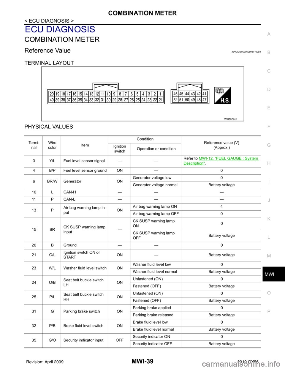
TERMINAL LAYOUT
PHYSICAL VALUES
WKIA5724E
Te r m i - nal Wire
color Item Condition
Reference value (V)
(Approx.)
Ignition
switch Operation or condition
3 Y/L Fuel level sensor signal — —Refer to
MWI-12, "
FUEL GAUGE : System
Description".
4 B/P Fuel level sensor ground ON —0
6 BR/W Generator ONGenerator voltage low
0
Generator voltage normal Battery voltage
10 L CAN-H —— —
11 P C A N - L —— —
13 P Air bag warning lamp in-
put ONAir bag warning lamp ON
4
Air bag warning lamp OFF 0
15 BR CK SUSP warning lamp
input —CK SUSP warning lamp
ON
0
CK SUSP warning lamp
OFF Battery voltage
20 B Ground —— 0
21 O/L Ignition switch ON or
START ON
— Battery voltage
23 W/L Washer fluid level switch ON Washer fluid level low
0
Washer fluid level normal Battery voltage
24 O/B Seat belt buckle switch
LH ONUnfastened (ON)
0
Fastened (OFF) Battery voltage
25 P/L Seat belt buckle switch
RH ONUnfastened (ON)
0
Fastened (OFF) Battery voltage
31 G Parking brake switch ON Parking brake applied
0
Parking brake released Battery voltage
32 P/B Brake fluid level switch ON Brake fluid level low
0
Brake fluid level normal Battery voltage
35 G/O Security indicator input OFF Security indicator ON
0
Security indicator OFF Battery voltage
Revision: April 20092010 QX56
Page 2802 of 4210
MWI-40
< ECU DIAGNOSIS >
COMBINATION METER
37 OIgnition switch ACC or
ON
—
— Battery voltage
40 P Battery power supply — —Battery voltage
46 BR Illumination output ——Refer to INL-9, "
System Description".
47 B Ground —— 0
50 W/R Vehicle speed signal out-
put (8-pulse) ONSpeedometer operated
[When vehicle speed is ap-
prox. 40 km/h (25 MPH)] NOTE:
Maximum voltage may be 12V due to spec-
ifications (connected units).
52 B Ground —— 0
Te r m i -
nal Wire
color Item Condition
Reference value (V)
(Approx.)
Ignition
switch Operation or condition
PKIC0643E
Revision: April 20092010 QX56
Page 2821 of 4210

MWI
COMBINATION METERMWI-59
< ECU DIAGNOSIS >
C
DE
F
G H
I
J
K L
M B A
O P
DTC IndexINFOID:0000000005146101
NOTE:
Function Specifications
Speedometer
Zero indication.
Tachometer
Fuel gauge
Engine coolant temperature gauge
Engine oil pressure gauge
Voltage gauge
Illumination control
Meter illumination Change to nighttime mode when communication is lost.
Segment LCD Odometer
Freeze current indication.
A/T position Display turns off.
Buzzer Buzzer turns off.
Warning lamp/indicator lamp ABS warning lamp
Lamp turns on when communication is lost.
Brake warning lamp
VDC OFF indicator lamp
SLIP indicator lamp
A/T CHECK warning lamp
Lamp turns off when communication is lost.
Oil pressure/coolant temperature
warning lamp
Light indicator
Malfunction indicator lamp
Master warning lamp
Air bag warning lamp
High beam indicator
Turn signal indicator lamp
CRUISE indicator lamp
Driver and passenger seat belt warn-
ing lamp
Lamp turns off when disconnected.
Charge warning lamp
Security indicator lamp
4WD indicator lamp
ATP indicator lamp
CK SUSP warning lamp
Low tire pressu
re warning lamp Lamp will flash every second for 1 minute and then stay on con-
tinuously thereafter.
CONSULT-III display
MalfunctionReference
page
CAN COMM CIRC
[U1000] Malfunction is detected in CAN communication.
CAUTION:
Even when there is no ma
lfunction on CAN communication system, malfunction may be
misinterpreted when battery has low voltag e (when maintaining 7 - 8 V for about 2 sec-
onds) or 10A fuse [No. 3, located in the fuse block (J/B)] is disconnected. MWI-26
VEHICLE SPEED
CIRC
[B2205]Malfunction is detected when an erroneous speed signal is input.
CAUTION:
Even when there is no malfunction on speed signal system, malfunction may be misin-
terpreted when battery has low voltage (whe
n maintaining 7 - 8 V for about 2 seconds). MWI-27
Revision: April 20092010 QX56
Page 2827 of 4210
MWI
BCM (BODY CONTROL MODULE)MWI-65
< ECU DIAGNOSIS >
C
DE
F
G H
I
J
K L
M B A
O P
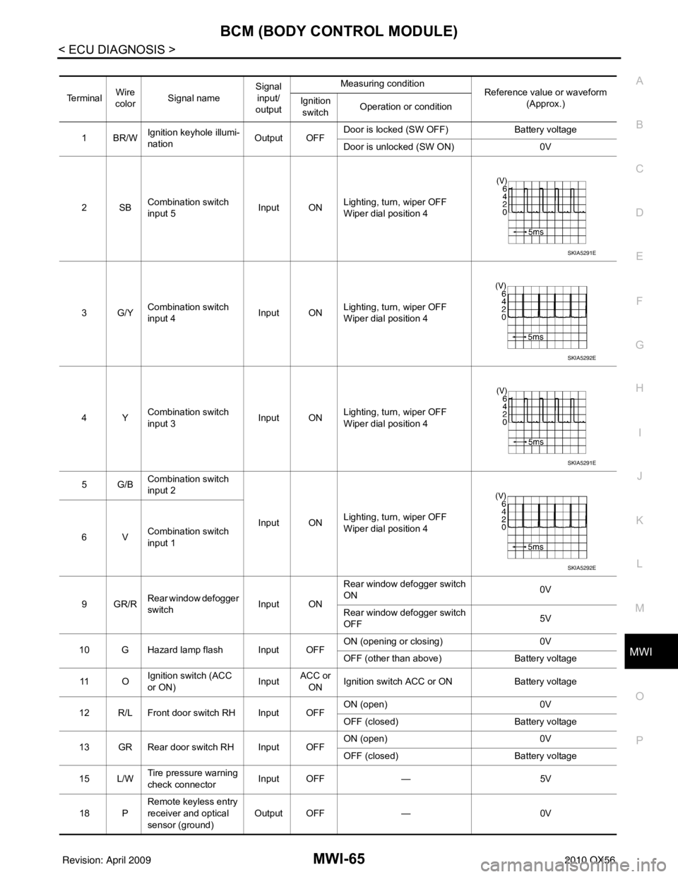
Te r m i n a l Wire
color Signal name Signal
input/
output Measuring condition
Reference value or waveform
(Approx.)
Ignition
switch Operation or condition
1BR/W Ignition keyhole illumi-
nation Output OFFDoor is locked (SW OFF)
Battery voltage
Door is unlocked (SW ON) 0V
2SB Combination switch
input 5 Input ON
Lighting, turn, wiper OFF
Wiper dial position 4
3G/Y Combination switch
input 4 Input ONLighting, turn, wiper OFF
Wiper dial position 4
4Y Combination switch
input 3 Input ON
Lighting, turn, wiper OFF
Wiper dial position 4
5G/B Combination switch
input 2
Input ONLighting, turn, wiper OFF
Wiper dial position 4
6V Combination switch
input 1
9GR/R Rear window defogger
switch
Input ONRear window defogger switch
ON
0V
Rear window defogger switch
OFF 5V
10 G Hazard lamp flash Input OFF ON (opening or closing)
0V
OFF (other than above) Battery voltage
11 O Ignition switch (ACC
or ON)
InputACC or
ON Ignition switch ACC or ON
Battery voltage
12 R/L Front door switch RH Input OFF ON (open)
0V
OFF (closed) Battery voltage
13 GR Rear door switch RH Input OFF ON (open)
0V
OFF (closed) Battery voltage
15 L/W Tire pressure warning
check connector
Input OFF
—5V
18 P Remote keyless entry
receiver and optical
sensor (ground)
Output OFF
—0V
SKIA5291E
SKIA5292E
SKIA5291E
SKIA5292E
Revision: April 20092010 QX56
Page 2828 of 4210
MWI-66
< ECU DIAGNOSIS >
BCM (BODY CONTROL MODULE)
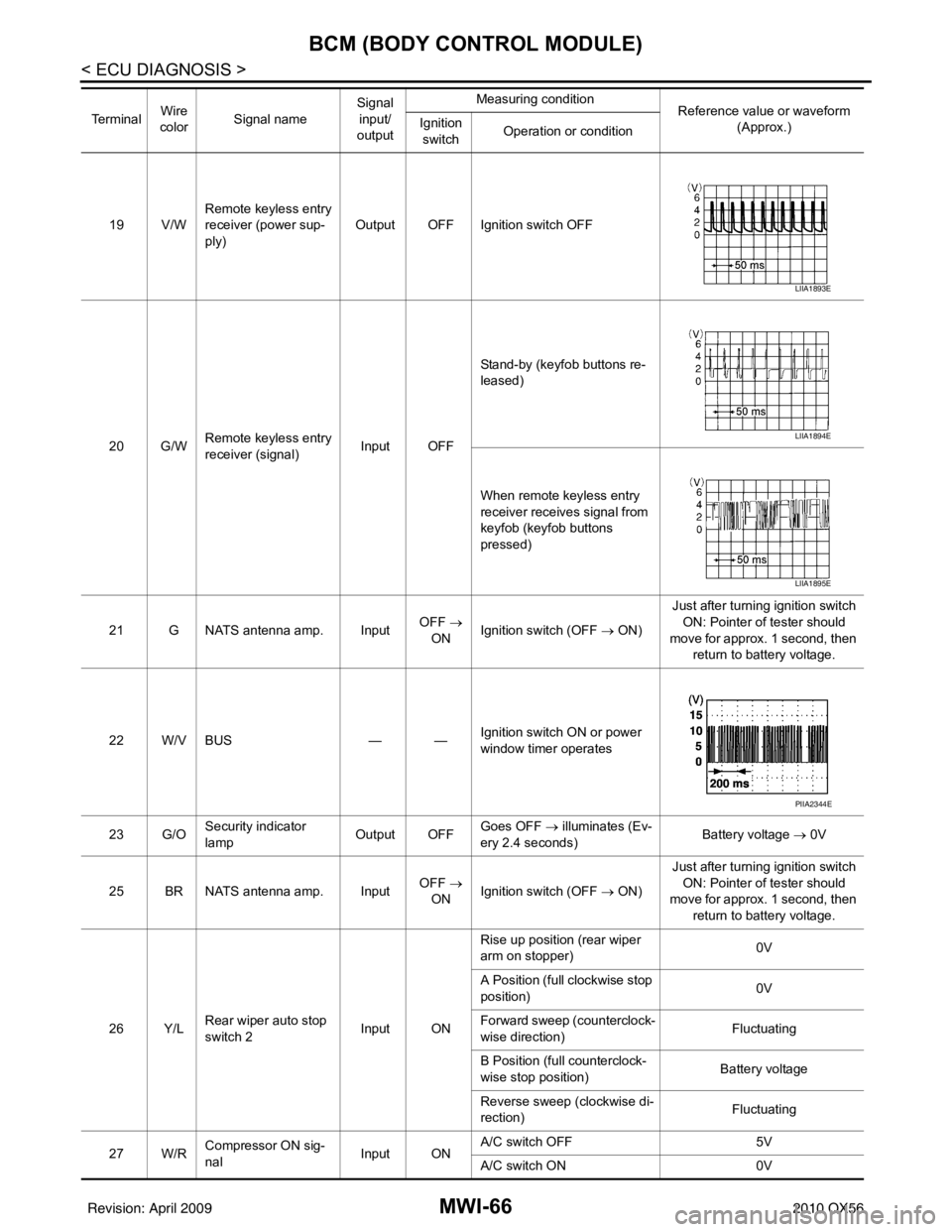
19 V/WRemote keyless entry
receiver (power sup-
ply) Output OFF Ignition switch OFF
20 G/W Remote keyless entry
receiver (signal) Input OFFStand-by (keyfob buttons re-
leased)
When remote keyless entry
receiver receives signal from
keyfob (keyfob buttons
pressed)
21 G NATS antenna amp. Input OFF
→
ON Ignition switch (OFF
→ ON)Just after turning ignition switch
ON: Pointer of tester should
move for approx. 1 second, then return to battery voltage.
22 W/V BUS — —Ignition switch ON or power
window timer operates
23 G/O Security indicator
lamp Output OFF
Goes OFF
→ illuminates (Ev-
ery 2.4 seconds) Battery voltage
→ 0V
25 BR NATS antenna amp. Input OFF
→
ON Ignition switch (OFF
→ ON)Just after turning ignition switch
ON: Pointer of tester should
move for approx. 1 second, then return to battery voltage.
26 Y/L Rear wiper auto stop
switch 2 Input ONRise up position (rear wiper
arm on stopper)
0V
A Position (full clockwise stop
position) 0V
Forward sweep (counterclock-
wise direction) Fluctuating
B Position (full counterclock-
wise stop position) Battery voltage
Reverse sweep (clockwise di-
rection) Fluctuating
27 W/R Compressor ON sig-
nal Input ONA/C switch OFF
5V
A/C switch ON 0V
Te r m i n a l
Wire
color Signal name Signal
input/
output Measuring condition
Reference value or waveform
(Approx.)
Ignition
switch Operation or condition
LIIA1893E
LIIA1894E
LIIA1895E
PIIA2344E
Revision: April 20092010 QX56
Page 2829 of 4210
MWI
BCM (BODY CONTROL MODULE)MWI-67
< ECU DIAGNOSIS >
C
DE
F
G H
I
J
K L
M B A
O P
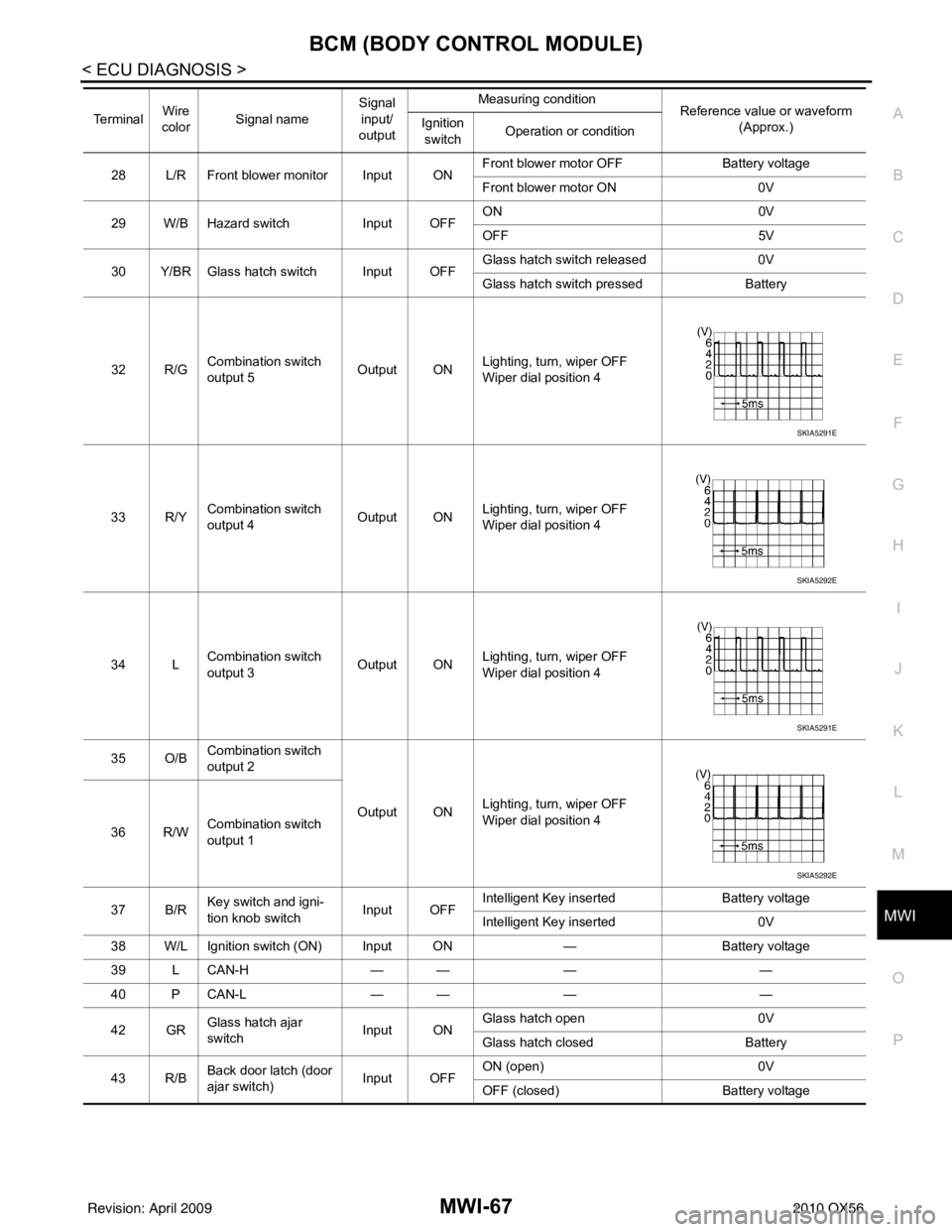
28 L/R Front blower monitor Input ON Front blower motor OFF Battery voltage
Front blower motor ON
0V
29 W/B Hazard switch Input OFFON
0V
OFF 5V
30 Y/BR Glass hatch switch Input OFF Glass hatch switch released
0V
Glass hatch switch pressed Battery
32 R/G Combination switch
output 5
Output ONLighting, turn, wiper OFF
Wiper dial position 4
33 R/Y Combination switch
output 4 Output ONLighting, turn, wiper OFF
Wiper dial position 4
34 L Combination switch
output 3 Output ON
Lighting, turn, wiper OFF
Wiper dial position 4
35 O/B Combination switch
output 2
Output ONLighting, turn, wiper OFF
Wiper dial position 4
36 R/W Combination switch
output 1
37 B/R Key switch and igni-
tion knob switch Input OFFIntelligent Key inserted
Battery voltage
Intelligent Key inserted 0V
38 W/L Ignition switch (ON) Input ON —Battery voltage
39 L CAN-H — —— —
40 P CAN-L — —— —
42 GR Glass hatch ajar
switch Input ONGlass hatch open
0V
Glass hatch closed Battery
43 R/B Back door latch (door
ajar switch) Input OFFON (open)
0V
OFF (closed) Battery voltage
Te r m i n a l
Wire
color Signal name Signal
input/
output Measuring condition
Reference value or waveform
(Approx.)
Ignition
switch Operation or condition
SKIA5291E
SKIA5292E
SKIA5291E
SKIA5292E
Revision: April 20092010 QX56
Page 2830 of 4210
MWI-68
< ECU DIAGNOSIS >
BCM (BODY CONTROL MODULE)
44 ORear wiper auto stop
switch 1 Input ONRise up position (rear wiper
arm on stopper)
0V
A Position (full clockwise stop
position) Battery voltage
Forward sweep (counterclock-
wise direction) Fluctuating
B Position (full counterclock-
wise stop position) 0V
Reverse sweep (clockwise di-
rection) Fluctuating
47 SB Front door switch LH Input OFF ON (open)
0V
OFF (closed) Battery voltage
48 R/Y Rear door switch LH Input OFF ON (open)
0V
OFF (closed) Battery voltage
49 R Cargo lamp Output OFFAny door open (ON)
0V
All doors closed (OFF) Battery voltage
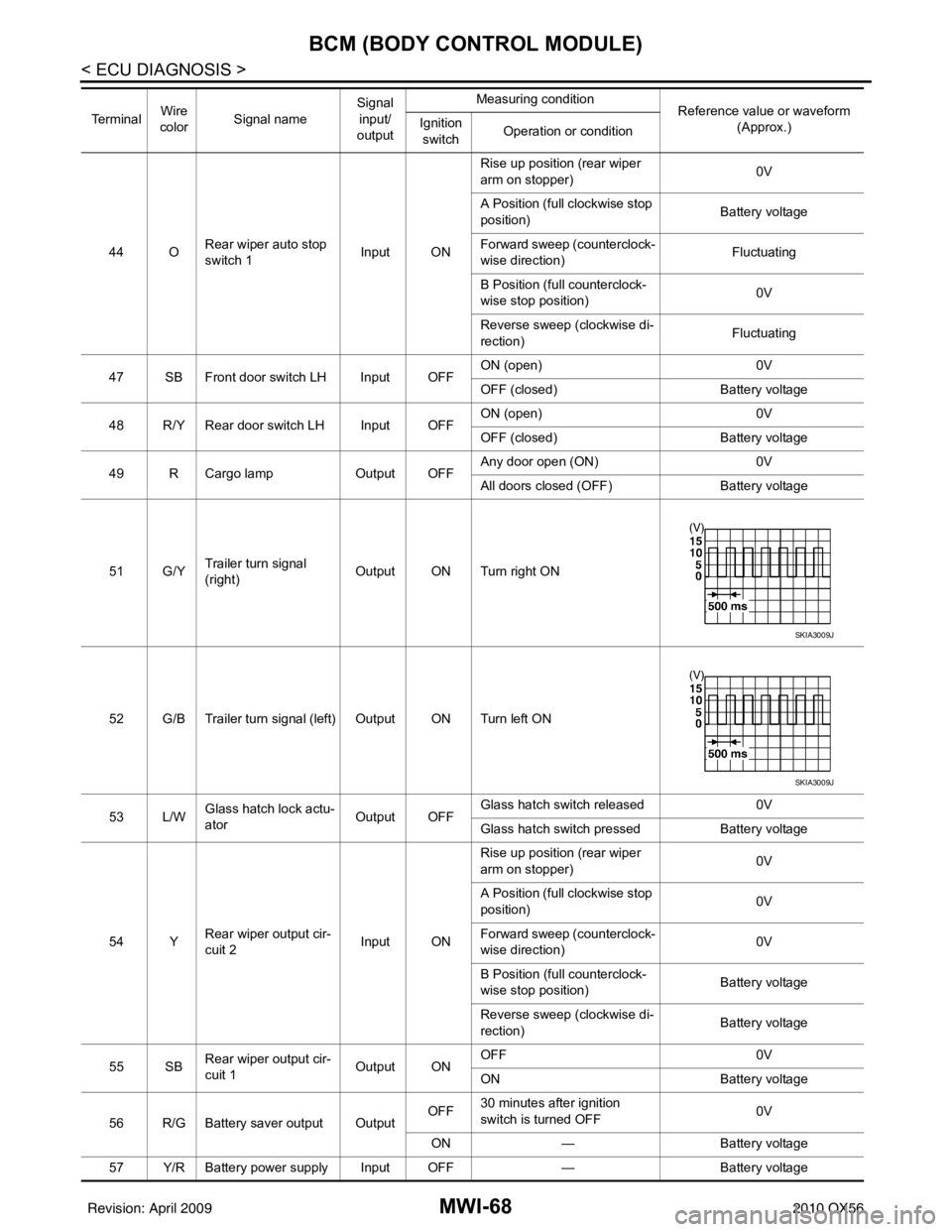
51 G/Y Trailer turn signal
(right) Output ON Turn right ON
52 G/B Trailer turn signal (l eft) Output ON Turn left ON
53 L/W Glass hatch lock actu-
ator
Output OFFGlass hatch switch released
0V
Glass hatch switch pressed Battery voltage
54 Y Rear wiper output cir-
cuit 2 Input ONRise up position (rear wiper
arm on stopper)
0V
A Position (full clockwise stop
position) 0V
Forward sweep (counterclock-
wise direction) 0V
B Position (full counterclock-
wise stop position) Battery voltage
Reverse sweep (clockwise di-
rection) Battery voltage
55 SB Rear wiper output cir-
cuit 1 Output ONOFF
0V
ON Battery voltage
56 R/G Battery saver output Output OFF
30 minutes after ignition
switch is turned OFF 0V
ON — Battery voltage
57 Y/R Battery power supply Input OFF —Battery voltage
Te r m i n a l
Wire
color Signal name Signal
input/
output Measuring condition
Reference value or waveform
(Approx.)
Ignition
switch Operation or condition
SKIA3009J
SKIA3009J
Revision: April 20092010 QX56
Page 2831 of 4210
MWI
BCM (BODY CONTROL MODULE)MWI-69
< ECU DIAGNOSIS >
C
DE
F
G H
I
J
K L
M B A
O P
58 W/R Optical sensor Input ONWhen optical sensor is illumi-
nated
3.1V or more
When optical sensor is not illu-
minated 0.6V or less
59 G Front door lock as-
sembly LH actuator
(unlock) Output OFF
OFF (neutral)
0V
ON (unlock) Battery voltage
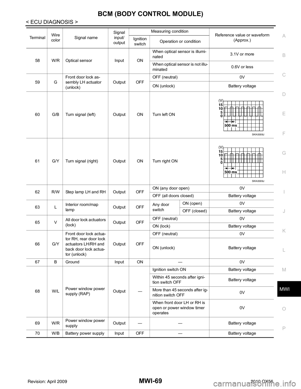
60 G/B Turn signal (left) Output ON Turn left ON
61 G/Y Turn signal (right) Output ON Turn right ON
62 R/W Step lamp LH and RH Output OFF ON (any door open)
0V
OFF (all doors closed) Battery voltage
63 L Interior room/map
lamp Output OFFAny door
switchON (open)
0V
OFF (closed) Battery voltage
65 V All door lock actuators
(lock) Output OFFOFF (neutral)
0V
ON (lock) Battery voltage
66 G/Y Front door lock actua-
tor RH, rear door lock
actuators LH/RH and
back door lock actua-
tor (unlock) Output OFF
OFF (neutral)
0V
ON (unlock) Battery voltage
67 B Ground Input ON—0V
68 W/L Power window power
supply (RAP) Output —Ignition switch ON
Battery voltage
Within 45 seconds after igni-
tion switch OFF Battery voltage
More than 45 seconds after ig-
nition switch OFF 0V
When front door LH or RH is
open or power window timer
operates 0V
69 W/R Power window power
supply
Output —
—Battery voltage
70 W/B Battery power supply Input OFF —Battery voltage
Te r m i n a l
Wire
color Signal name Signal
input/
output Measuring condition
Reference value or waveform
(Approx.)
Ignition
switch Operation or condition
SKIA3009J
SKIA3009J
Revision: April 20092010 QX56