2010 INFINITI QX56 ECU
[x] Cancel search: ECUPage 2906 of 4210
![INFINITI QX56 2010 Factory Service Manual PCS
IPDM E/R (INTELLIGENT POWER DISTRIBUTION MODULE ENGINE ROOM)
PCS-31
< ECU DIAGNOSIS > [IPDM E/R]
C
D
E
F
G H
I
J
K L
B A
O P
N
If No CAN Communication Is Available With BCM
IGNITION RELAY MALFUNCT INFINITI QX56 2010 Factory Service Manual PCS
IPDM E/R (INTELLIGENT POWER DISTRIBUTION MODULE ENGINE ROOM)
PCS-31
< ECU DIAGNOSIS > [IPDM E/R]
C
D
E
F
G H
I
J
K L
B A
O P
N
If No CAN Communication Is Available With BCM
IGNITION RELAY MALFUNCT](/manual-img/42/57032/w960_57032-2905.png)
PCS
IPDM E/R (INTELLIGENT POWER DISTRIBUTION MODULE ENGINE ROOM)
PCS-31
< ECU DIAGNOSIS > [IPDM E/R]
C
D
E
F
G H
I
J
K L
B A
O P
N
If No CAN Communication Is Available With BCM
IGNITION RELAY MALFUNCTION DETECTION FUNCTION
• IPDM E/R monitors the voltage at the contact circuit and excitation coil circuit of the ignition relay inside it.
• IPDM E/R judges the ignition relay error if the voltage differs between the contact circuit and the excitation
coil circuit.
• If the ignition relay cannot turn OFF due to contact seizure, it activates the tail lamp relay for 10 minutes to alert the user to the ignition relay malfunction when the ignition switch is turned OFF.
NOTE:
The tail lamp turns OFF when the ignition switch is turned ON.
FRONT WIPER CONTROL
IPDM E/R detects front wiper stop posit ion by a front wiper auto stop signal.
When a front wiper auto stop signal is in the conditions listed below, IPDM E/R stops power supply to wiper
after repeating a front wiper 10 second activation and 20 second stop five times.
NOTE:
This operation status can be confirmed on the IPDM E/R “DATA MONITOR” that displays “Block” for the item
“WIP PROT” while the wiper is stopped.
STARTER MOTOR PROTECTION FUNCTION
IPDM E/R turns OFF the starter control relay to protect the starter motor when the starter control relay remains
active for 90 seconds.
Control part Fail-safe in operation
Cooling fan • Turns ON the cooling fan relay when the ignition switch is turned ON
• Turns OFF the cooling fan relay when the ignition switch is turned OFF
Control part
Fail-safe in operation
Headlamp • Turns ON the headlamp low relay when the ignition switch is turned ON
• Turns OFF the headlamp low relay when the ignition switch is turned OFF
• Headlamp high LH/RH relays OFF
•Parking lamps
• License plate lamps
• Tail lamps • Turns ON the tail lamp relay when the ignition switch is turned ON
• Turns OFF the tail lamp relay when the ignition switch is turned OFF
Front wiper • The status just before activation of fail-safe control is maintained until the ignition
switch is turned OFF while the front wiper is operating at LO or HI speed.
• The wiper is operated at LO speed until the ignition switch is turned OFF if the fail- safe control is activated while the front wipe r is set in the INT mode and the front wiper
motor is operating.
Rear window defogger Rear window defogger relay OFF
A/C compressor A/C relay OFF
Front fog lamps Front fog lamp relay OFF
Ignition switch Ignition relayTail lamp relay
ON ON —
OFF OFF —
Ignition switchFront wiper switch Auto stop signal
ON OFF
Front wiper stop position signal cannot be
input 10 seconds.
ON The signal does not change for 10 seconds.
Revision: April 20092010 QX56
Page 2907 of 4210
![INFINITI QX56 2010 Factory Service Manual PCS-32
< ECU DIAGNOSIS >[IPDM E/R]
IPDM E/R (INTELLIGENT POWER DI
STRIBUTION MODULE ENGINE ROOM)
DTC Index
INFOID:0000000005146517
NOTE:
The details of TIME display are as follows.
• CRNT: The malfu INFINITI QX56 2010 Factory Service Manual PCS-32
< ECU DIAGNOSIS >[IPDM E/R]
IPDM E/R (INTELLIGENT POWER DI
STRIBUTION MODULE ENGINE ROOM)
DTC Index
INFOID:0000000005146517
NOTE:
The details of TIME display are as follows.
• CRNT: The malfu](/manual-img/42/57032/w960_57032-2906.png)
PCS-32
< ECU DIAGNOSIS >[IPDM E/R]
IPDM E/R (INTELLIGENT POWER DI
STRIBUTION MODULE ENGINE ROOM)
DTC Index
INFOID:0000000005146517
NOTE:
The details of TIME display are as follows.
• CRNT: The malfunctions that are detected now
• 1 - 39: The number is indicated when it is normal at present and a malfunction was detected in the past. It
increases like 0 → 1 → 2 ··· 38 → 39 after returning to the normal condition whenever IGN OFF → ON. It is
fixed to 39 until the self-diagnosis results are erased if it is over 39. It returns to 0 when a malfunction is
detected again in the process.
CONSULT-III display Fail-safe
TIMENOTERefer to
No DTC is detected.
further testing
may be required. ————
U1000: CAN COMM CIRCUIT ×CRNT 1 – 39 PCS-17
Revision: April 20092010 QX56
Page 2918 of 4210

PG-8
< BASIC INSPECTION >
INSPECTION AND ADJUSTMENT
INSPECTION AND ADJUSTMENT
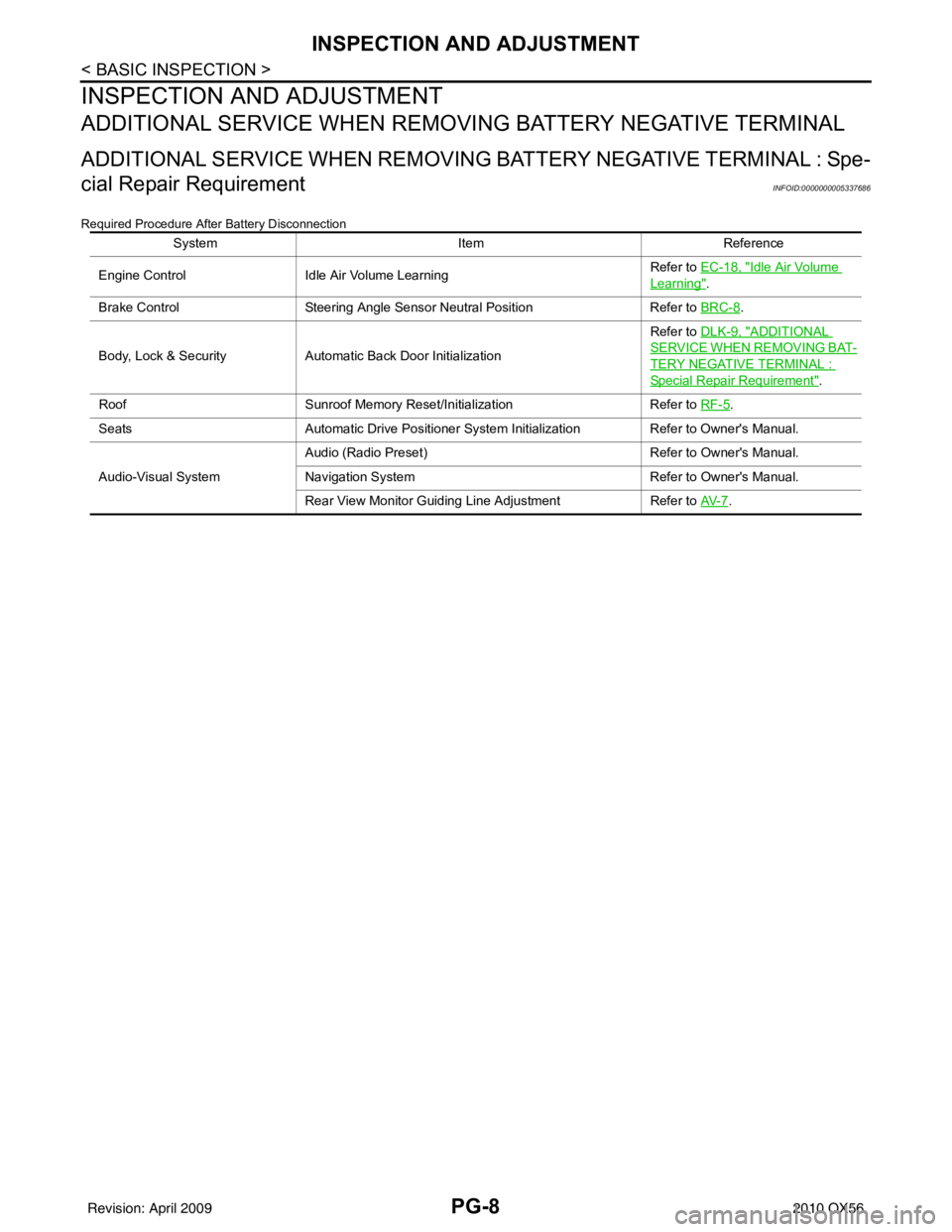
ADDITIONAL SERVICE WHEN REMOVING BATTERY NEGATIVE TERMINAL
ADDITIONAL SERVICE WHEN REMOVING BATTERY NEGATIVE TERMINAL : Spe-
cial Repair Requirement
INFOID:0000000005337686
Required Procedure After Battery Disconnection
System ItemReference
Engine Control Idle Air Volume Learning Refer to EC-18, "
Idle Air Volume
Learning".
Brake Control Steering Angle Sensor Neutral Position Refer to BRC-8
.
Body, Lock & Security Automatic Back Door Initialization Refer to DLK-9, "
ADDITIONAL
SERVICE WHEN REMOVING BAT-
TERY NEGATIVE TERMINAL :
Special Repair Requirement".
Roof Sunroof Memory Reset/Initialization Refer to RF-5
.
Seats Automatic Drive Positioner System Initialization Refer to Owner's Manual.
Audio-Visual System Audio (Radio Preset)
Refer to Owner's Manual.
Navigation System Refer to Owner's Manual.
Rear View Monitor Guiding Line Adjustment Refer to AV- 7
.
Revision: April 20092010 QX56
Page 2986 of 4210

PWC-1
BODY EXTERIOR, DOORS, ROOF & VEHICLE SECURITY
C
DE
F
G H
I
J
L
M
SECTION PWC
A
B
PWC
N
O P
CONTENTS
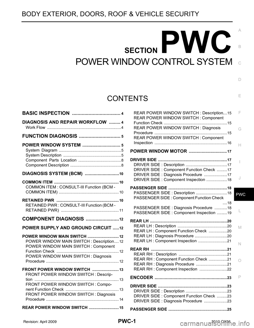
POWER WINDOW CONTROL SYSTEM
BASIC INSPECTION ....... .............................4
DIAGNOSIS AND REPAIR WORKFLOW ..... .....4
Work Flow ........................................................... ......4
FUNCTION DIAGNOSIS ...............................5
POWER WINDOW SYST EM ...............................5
System Diagram ................................................. ......5
System Description ...................................................5
Component Parts Location ......................................8
Component Description .............................................8
DIAGNOSIS SYSTEM (BCM) ............................10
COMMON ITEM ..................................................... ....10
COMMON ITEM : CONSULT-III Function (BCM -
COMMON ITEM) .....................................................
10
RETAINED PWR .......................................................10
RETAINED PWR : CONSULT-III Function (BCM -
RETAINED PWR) ...................................................
11
COMPONENT DIAGNOSIS .........................12
POWER SUPPLY AND GROUND CIRCUIT .. ....12
POWER WINDOW MAIN SWITCH ........................ ....12
POWER WINDOW MAIN SWITCH : Description ....12
POWER WINDOW MAIN SWITCH : Component
Function Check .......................................................
12
POWER WINDOW MAIN SWITCH : Diagnosis
Procedure ................................................................
12
FRONT POWER WINDOW SWITCH .................... ....13
FRONT POWER WINDOW SWITCH : Descrip-
tion ..........................................................................
13
FRONT POWER WINDOW SWITCH : Compo-
nent Function Check ...............................................
13
FRONT POWER WINDOW SWITCH : Diagnosis
Procedure ................................................................
14
REAR POWER WINDOW SWITCH ....................... ....15
REAR POWER WINDOW SWITCH : Description ....15
REAR POWER WINDOW SWITCH : Component
Function Check ........................................................
15
REAR POWER WINDOW SWITCH : Diagnosis
Procedure ................................................................
15
REAR POWER WINDOW SWITCH : Component
Inspection ................................................................
16
POWER WINDOW MOTOR ..............................17
DRIVER SIDE ......................................................... ....17
DRIVER SIDE : Description .....................................17
DRIVER SIDE : Component Function Check ..........17
DRIVER SIDE : Diagnosis Procedure .....................17
DRIVER SIDE : Component Inspection ...................18
PASSENGER SIDE ....................................................18
PASSENGER SIDE : Descript ion ............................18
PASSENGER SIDE : Component Function Check
....
18
PASSENGER SIDE : Diagnosis Procedure ............18
PASSENGER SIDE : Component Inspection ..........19
REAR LH ................................................................ ....20
REAR LH : Description ............................................20
REAR LH : Component Function Check .................20
REAR LH : Diagnosis Procedure .............................20
REAR LH : Component Inspection ..........................21
REAR RH ............................................................... ....21
REAR RH : Description ...........................................21
REAR RH : Component Function Check .................21
REAR RH : Diagnosis Procedure ............................21
REAR RH : Component Inspection .........................22
ENCODER .........................................................23
DRIVER SIDE ......................................................... ....23
DRIVER SIDE : Description .....................................23
DRIVER SIDE : Component Function Check ..........23
DRIVER SIDE : Diagnosis Procedure .....................23
PASSENGER SIDE ....................................................25
Revision: April 20092010 QX56
Page 2987 of 4210

PWC-2
PASSENGER SIDE : Description ...........................25
PASSENGER SIDE : Compo nent Function Check
...
25
PASSENGER SIDE : Diagnosis Procedure ........ ...25
REAR LH ................................................................ ...28
REAR LH : Description ...........................................28
REAR LH : Component Function Check ................28
REAR LH : Diagnosis Procedure ............................28
REAR RH ............................................................... ...30
REAR RH : Description ..........................................31
REAR RH : Component Function Check ................31
REAR RH : Diagnosis Procedure ...........................31
DOOR SWITCH .................................................34
Description ..............................................................34
Component Function Check ...................................34
Diagnosis Procedure ..............................................34
Component Inspection ............................................35
DOOR KEY CYLINDER SWITCH ......................36
Description ........................................................... ...36
Component Function Check ...................................36
Diagnosis Procedure ..............................................36
Component Inspection ............................................37
POWER WINDOW SERIAL LINK .....................39
POWER WINDOW MAIN SWITCH ........................ ...39
POWER WINDOW MAIN SWITCH : Description ...39
POWER WINDOW MAIN SWITCH : Component
Function Check .......................................................
39
POWER WINDOW MAIN SWITCH : Diagnosis
Procedure ...............................................................
39
FRONT POWER WINDOW SWITCH ..................... ...40
FRONT POWER WINDOW SWITCH : Descrip-
tion ..........................................................................
40
FRONT POWER WINDOW SWITCH : Compo-
nent Function Check ...............................................
40
FRONT POWER WINDOW SWITCH : Diagnosis
Procedure ...............................................................
41
REAR POWER WINDOW SWITCH ....................... ...42
REAR POWER WINDOW SWITCH : Power Win-
dow Serial Link Check Rear LH or RH ...................
42
POWER WINDOW LOCK SWITCH ...................43
Description ........................................................... ...43
Component Function Check ...................................43
REAR POWER VENT WINDOW SWITCH
CIRCUIT CHECK ...............................................
44
Description ........................................................... ...44
Diagnosis Procedure ..............................................44
REAR POWER VENT WINDOW MOTOR LH
CIRCUIT CHECK ...............................................
45
Description ........................................................... ...45
Diagnosis Procedure ..............................................45
REAR POWER VENT WINDOW MOTOR RH
CIRCUIT CHECK ...............................................
46
Description ........................................................... ...46
Diagnosis Procedure ...............................................46
REAR POWER VENT WINDOW RELAY
(OPEN) CHECK .................................................
47
Description ........................................................... ...47
Diagnosis Procedure ...............................................47
REAR POWER VENT WINDOW RELAY
(CLOSE) CHECK ...............................................
49
Description ........................................................... ...49
Diagnosis Procedure ...............................................49
ECU DIAGNOSIS .......................................51
POWER WINDOW MAIN SWITCH ................ ...51
Reference Value .................................................. ...51
Wiring Diagram .......................................................53
Fail Safe .................................................................64
FRONT POWER WINDOW SWITCH ................66
Reference Value .................................................. ...66
Wiring Diagram .......................................................68
Fail Safe .................................................................79
BCM (BODY CONTROL MODULE) ..................81
Reference Value .................................................. ...81
Terminal Layout ......................................................84
Physical Values .......................................................84
Wiring Diagram .......................................................90
Fail Safe .................................................................94
DTC Inspection Priority Chart ...............................95
DTC Index ..............................................................95
SYMPTOM DIAGNOSIS ............................97
NONE OF THE POWER WINDOWS CAN BE
OPERATED USING ANY SWITCH ................ ...
97
Diagnosis Procedure ............................................ ...97
DRIVER SIDE POWER WINDOW ALONE
DOES NOT OPERATE ......................................
98
Diagnosis Procedure ............................................ ...98
FRONT PASSENGER SIDE POWER WIN-
DOW ALONE DOES NOT OPERATE ...............
99
Diagnosis Procedure ............................................ ...99
REAR LH SIDE POWER WINDOW ALONE
DOES NOT OPERATE .....................................
100
Diagnosis Procedure ............................................ .100
REAR RH SIDE POWER WINDOW ALONE
DOES NOT OPERATE .....................................
101
Diagnosis Procedure ............................................ .101
ANTI-PINCH SYSTEM DOES NOT OPERATE
NORMALLY (DRIVER SIDE) ...........................
102
Diagnosis Procedure ............................................ .102
Revision: April 20092010 QX56
Page 2995 of 4210

PWC-10
< FUNCTION DIAGNOSIS >
DIAGNOSIS SYSTEM (BCM)
DIAGNOSIS SYSTEM (BCM)
COMMON ITEM
COMMON ITEM : CONSULT-III Function (BCM - COMMON ITEM)INFOID:0000000005369205
APPLICATION ITEM
CONSULT-III performs the following functions via CAN communication with BCM.
SYSTEM APPLICATION
BCM can perform the following functions for each system.
NOTE:
It can perform the diagnosis modes except the following for all sub system selection items.
RETAINED PWR
Diagnosis mode Function Description
WORK SUPPORT Changes the setting for each system function.
SELF-DIAG RESULTS Displays the diagnosis results judged by BCM. Refer to BCS-54, "
DTCIndex".
CAN DIAG SUPPORT MNTR Monitors the reception status of CAN communication viewed from BCM.
DATA MONITOR The BCM input/output signals are displayed.
ACTIVE TEST The signals used to activate each device are forcibly supplied from BCM.
ECU IDENTIFICATION The BCM part number is displayed.
CONFIGURATION • Enables to read and save the vehicle specification.
• Enables to write the vehicle specification when replacing BCM.
System
Sub system selection item Diagnosis mode
WORK SUPPORT DATA MONITOR ACTIVE TEST
BCM BCM ×
Door lock DOOR LOCK ×××
Rear window defogger REAR DEFOGGER ×
Warning chime BUZZER ××
Interior room lamp timer INT LAMP ×××
Remote keyless entry system MULTI REMOTE ENT ××
Exterior lamp HEAD LAMP ×××
Wiper and washer WIPER ×××
Turn signal and hazard warning lamps FLASHER ××
Air conditioner AIR CONDITONER ×
Intelligent Key system INTELLIGENT KEY ×
Combination switch COMB SW ×
Immobilizer IMMU ××
Interior room lamp battery saver BATTERY SAVER ×××
Back door open TRUNK ××
RAP (retained accessory power) RETAINED PWR ×××
Signal buffer system SIGNAL BUFFER ××
TPMS (tire pressure monitoring sys-
tem) AIR PRESSURE MONITOR
×××
Vehicle security system THEFT ALM ×××
Panic alarm system PANIC ALARM ×
Revision: April 20092010 QX56
Page 3036 of 4210

POWER WINDOW MAIN SWITCHPWC-51
< ECU DIAGNOSIS >
C
DE
F
G H
I
J
L
M A
B
PWC
N
O P
ECU DIAGNOSIS
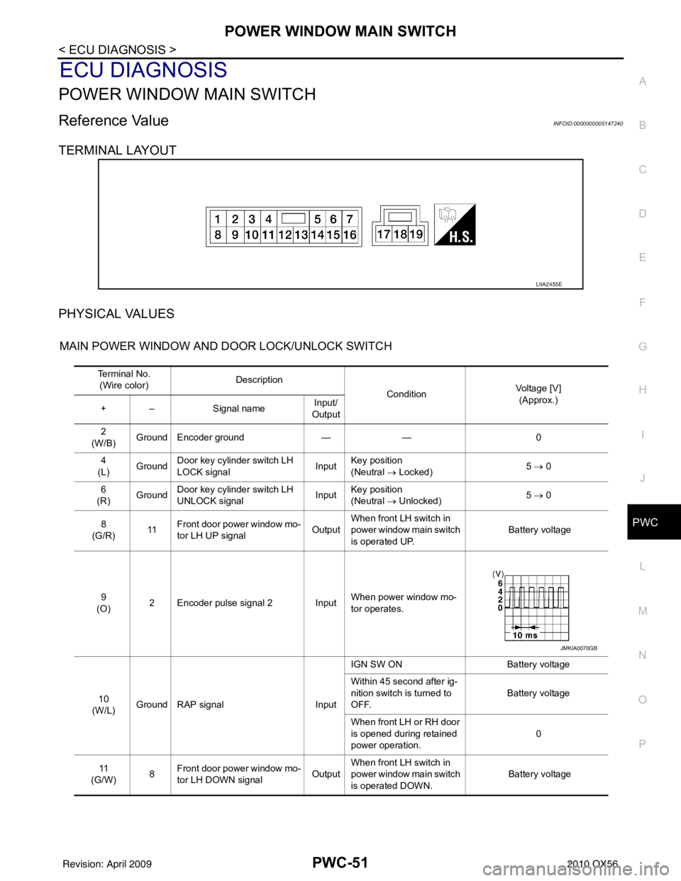
POWER WINDOW MAIN SWITCH
Reference Value INFOID:0000000005147240
TERMINAL LAYOUT
PHYSICAL VALUES
MAIN POWER WINDOW AND DOOR LOCK/UNLOCK SWITCH
LIIA2455E
Te r m i n a l N o . (Wire color) Description
ConditionVoltage [V]
(Approx.)
+ – Signal name Input/
Output
2
(W/B) Ground Encoder ground
—— 0
4
(L) Ground
Door key cylinder switch LH
LOCK signal Input
Key position
(Neutral
→ Locked) 5
→ 0
6
(R) Ground Door key cylinder switch LH
UNLOCK signal InputKey position
(Neutral
→ Unlocked) 5
→ 0
8
(G/R) 11Front door power window mo-
tor LH UP signal OutputWhen front LH switch in
power window main switch
is operated UP. Battery voltage
9
(O) 2 Encoder pulse signal 2 Input When power window mo-
tor operates.
10
(W/L) Ground RAP signal
InputIGN SW ON
Battery voltage
Within 45 second after ig-
nition switch is turned to
OFF. Battery voltage
When front LH or RH door
is opened during retained
power operation. 0
11
(G/W) 8
Front door power window mo-
tor LH DOWN signal OutputWhen front LH switch in
power window main switch
is operated DOWN. Battery voltage
JMKIA0070GB
Revision: April 20092010 QX56
Page 3037 of 4210

PWC-52
< ECU DIAGNOSIS >
POWER WINDOW MAIN SWITCH
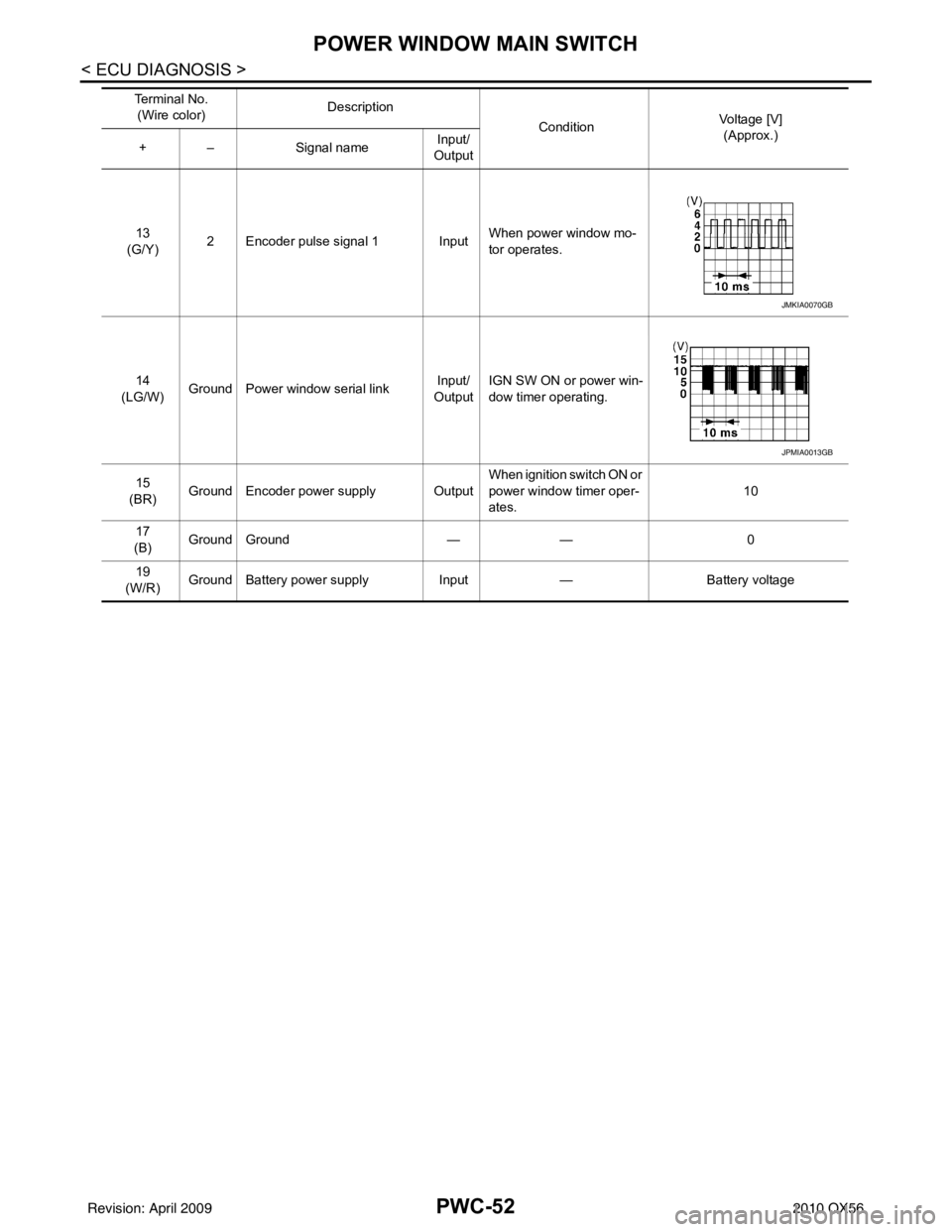
13
(G/Y) 2 Encoder pulse signal 1 Input When power window mo-
tor operates.
14
(LG/W) Ground Power window serial link Input/
Output IGN SW ON or power win-
dow timer operating.
15
(BR) Ground Encoder power supply Output When ignition switch ON or
power window timer oper-
ates.10
17
(B) Ground Ground
—— 0
19
(W/R) Ground Battery power supply
Input— Battery voltage
Te r m i n a l N o .
(Wire color) Description
ConditionVoltage [V]
(Approx.)
+ – Signal name Input/
Output
JMKIA0070GB
JPMIA0013GB
Revision: April 20092010 QX56