2010 INFINITI QX56 service
[x] Cancel search: servicePage 3841 of 4210
TM-146
< PREPARATION >
PREPARATION
PREPARATION
PREPARATION
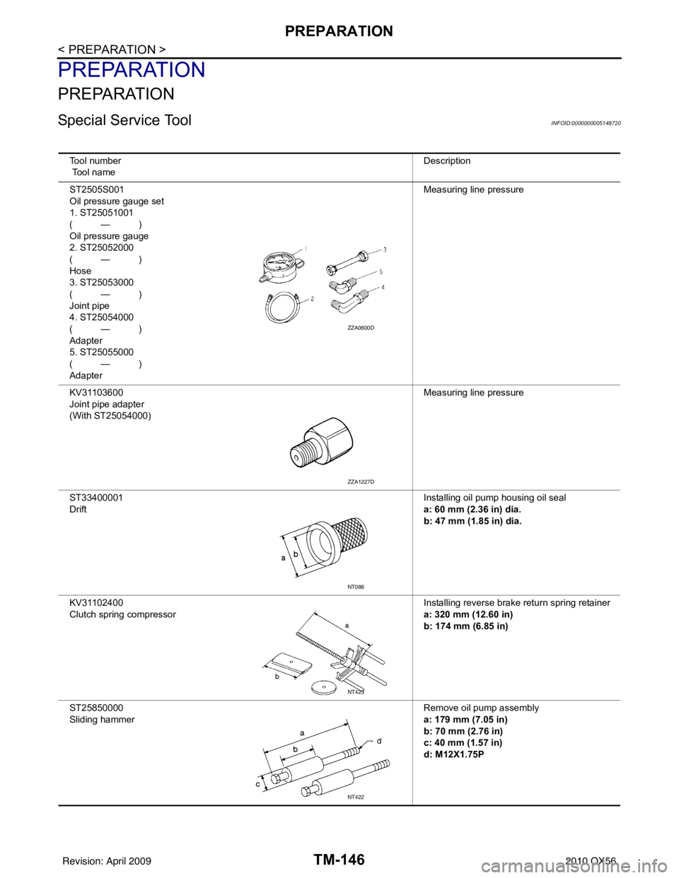
Special Service ToolINFOID:0000000005148720
Tool number
Tool nameDescription
ST2505S001
Oil pressure gauge set
1. ST25051001
(—)
Oil pressure gauge
2. ST25052000
(—)
Hose
3. ST25053000
(—)
Joint pipe
4. ST25054000
(—)
Adapter
5. ST25055000
(—)
Adapter Measuring line pressure
KV31103600
Joint pipe adapter
(With ST25054000) Measuring line pressure
ST33400001
Drift Installing oil pump housing oil seal
a: 60 mm (2.36 in) dia.
b: 47 mm (1.85 in) dia.
KV31102400
Clutch spring compressor Installing reverse brake return spring retainer
a: 320 mm (12.60 in)
b: 174 mm (6.85 in)
ST25850000
Sliding hammer Remove oil pump assembly
a: 179 mm (7.05 in)
b: 70 mm (2.76 in)
c: 40 mm (1.57 in)
d: M12X1.75P
ZZA0600D
ZZA1227D
NT086
NT423
NT422
Revision: April 20092010 QX56
Page 3842 of 4210
PREPARATIONTM-147
< PREPARATION >
CEF
G H
I
J
K L
M A
B
TM
N
O P
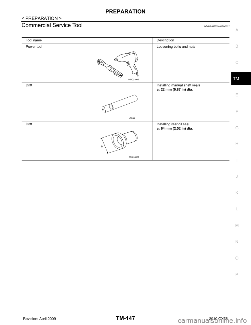
Commercial Service ToolINFOID:0000000005148721
Tool name Description
Power tool Loosening bolts and nuts
Drift Installing manual shaft seals
a: 22 mm (0.87 in) dia.
Drift Installing rear oil seal
a: 64 mm (2.52 in) dia.
PBIC0190E
NT083
SCIA5338E
Revision: April 20092010 QX56
Page 3847 of 4210
TM-152
< ON-VEHICLE MAINTENANCE >
A/T FLUID COOLER
A/T FLUID COOLER
A/T Fluid Cooler CleaningINFOID:0000000005148724
Whenever an A/T is repaired, overhauled, or replaced, the A/T fluid cooler mounted in the radiator must be
inspected and cleaned.
Metal debris and friction material, if present, can become trapped in the A/T fluid cooler. This debris can con-
taminate the newly serviced A/T or, in severe cases, can bloc k or restrict the flow of A/T fluid. In either case,
malfunction of the newly serviced A/T may result.
Debris, if present, may build up as A/T fluid enters the c ooler inlet. It will be necessary to back flush the cooler
through the cooler outlet in order to flush out any built up debris.
A/T FLUID COOLER CLEANING PROCEDURE
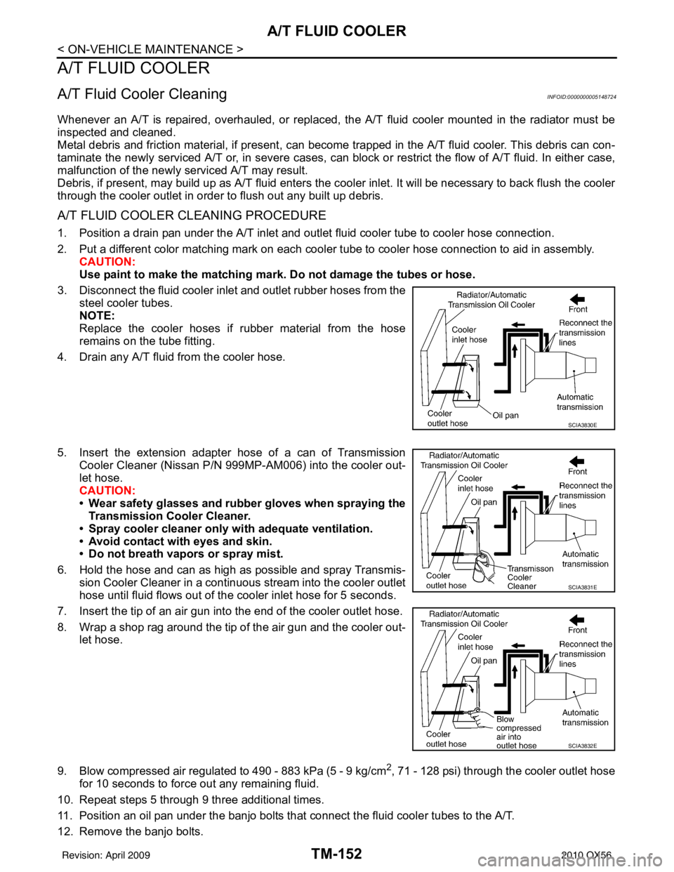
1. Position a drain pan under the A/T inlet and outlet fluid cooler tube to cooler hose connection.
2. Put a different color matching mark on each cooler tube to cooler hose connection to aid in assembly. CAUTION:
Use paint to make the matching mark. Do not damage the tubes or hose.
3. Disconnect the fluid cooler inlet and outlet rubber hoses from the steel cooler tubes.
NOTE:
Replace the cooler hoses if rubber material from the hose
remains on the tube fitting.
4. Drain any A/T fluid from the cooler hose.
5. Insert the extension adapter hose of a can of Transmission
Cooler Cleaner (Nissan P/N 999MP-AM006) into the cooler out-
let hose.
CAUTION:
• Wear safety glasses and rubber gloves when spraying the Transmission Cooler Cleaner.
• Spray cooler cleaner only wi th adequate ventilation.
• Avoid contact with eyes and skin.
• Do not breath vapors or spray mist.
6. Hold the hose and can as high as possible and spray Transmis- sion Cooler Cleaner in a continuous stream into the cooler outlet
hose until fluid flows out of the cooler inlet hose for 5 seconds.
7. Insert the tip of an air gun into the end of the cooler outlet hose.
8. Wrap a shop rag around the tip of the air gun and the cooler out- let hose.
9. Blow compressed air regulated to 490 - 883 kPa (5 - 9 kg/cm
2, 71 - 128 psi) through the cooler outlet hose
for 10 seconds to force out any remaining fluid.
10. Repeat steps 5 through 9 three additional times.
11. Position an oil pan under the banjo bolts that connect the fluid cooler tubes to the A/T.
12. Remove the banjo bolts.
SCIA3830E
SCIA3831E
SCIA3832E
Revision: April 20092010 QX56
Page 3849 of 4210
TM-154
< ON-VEHICLE MAINTENANCE >
A/T FLUID COOLER
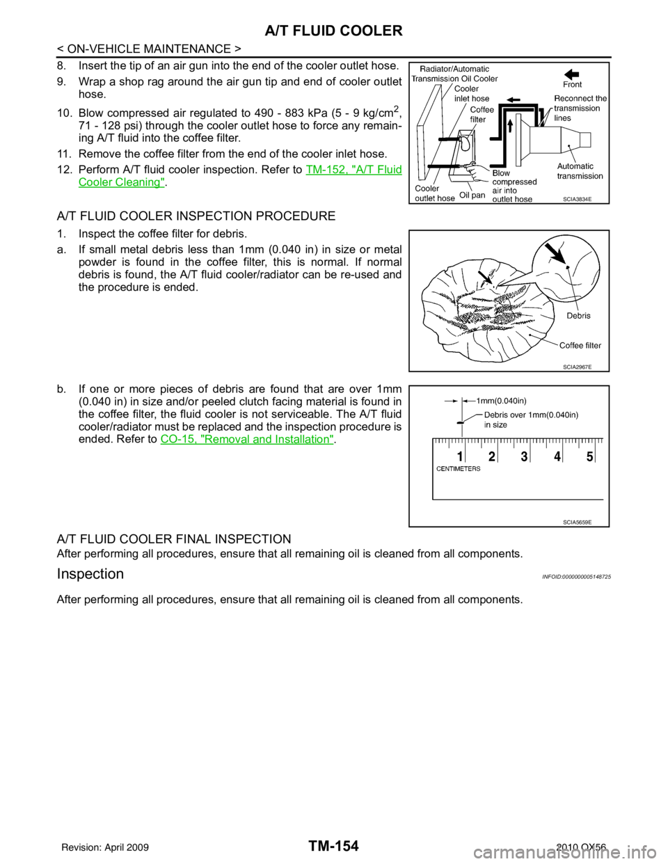
8. Insert the tip of an air gun into the end of the cooler outlet hose.
9. Wrap a shop rag around the air gun tip and end of cooler outlethose.
10. Blow compressed air regulated to 490 - 883 kPa (5 - 9 kg/cm
2,
71 - 128 psi) through the cooler outlet hose to force any remain-
ing A/T fluid into the coffee filter.
11. Remove the coffee filter from the end of the cooler inlet hose.
12. Perform A/T fluid cooler inspection. Refer to TM-152, "
A/T Fluid
Cooler Cleaning".
A/T FLUID COOLER INSPECTION PROCEDURE
1. Inspect the coffee filter for debris.
a. If small metal debris less than 1mm (0.040 in) in size or metal
powder is found in the coffee filter, this is normal. If normal
debris is found, the A/T fluid cooler/radiator can be re-used and
the procedure is ended.
b. If one or more pieces of debris are found that are over 1mm (0.040 in) in size and/or peeled clutch facing material is found in
the coffee filter, the fluid cooler is not serviceable. The A/T fluid
cooler/radiator must be replaced and the inspection procedure is
ended. Refer to CO-15, "
Removal and Installation".
A/T FLUID COOLER FINAL INSPECTION
After performing all procedures, ensure that all remaining oil is cleaned from all components.
InspectionINFOID:0000000005148725
After performing all procedures, ensure that all remaining oil is cleaned from all components.
SCIA3834E
SCIA2967E
SCIA5659E
Revision: April 20092010 QX56
Page 3885 of 4210
TM-190
< REMOVAL AND INSTALLATION >
TRANSMISSION ASSEMBLY
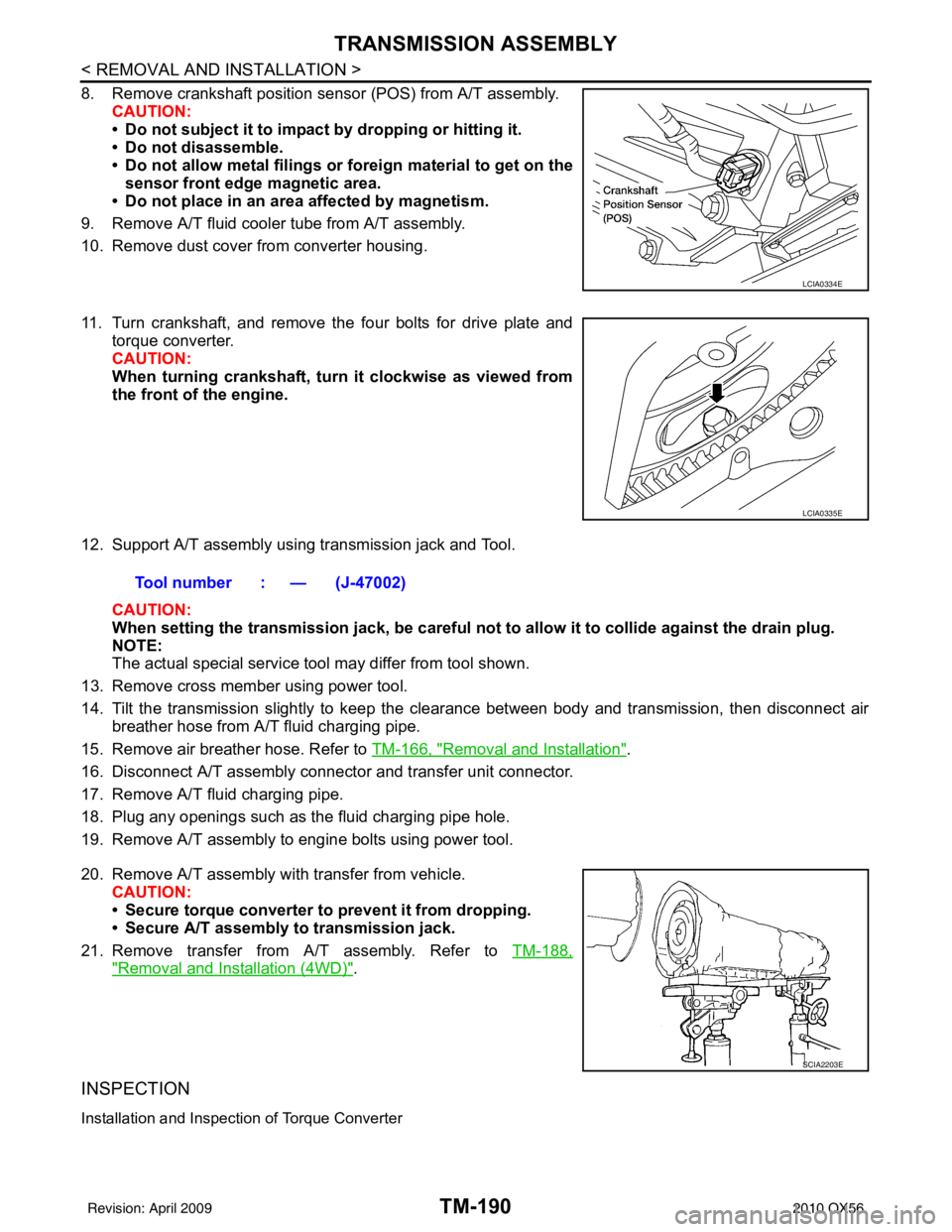
8. Remove crankshaft position sensor (POS) from A/T assembly.CAUTION:
• Do not subject it to impact by dropping or hitting it.
• Do not disassemble.
• Do not allow metal filings or fo reign material to get on the
sensor front edge magnetic area.
• Do not place in an area affected by magnetism.
9. Remove A/T fluid cooler tube from A/T assembly.
10. Remove dust cover from converter housing.
11. Turn crankshaft, and remove the four bolts for drive plate and torque converter.
CAUTION:
When turning crankshaft, turn it clockwise as viewed from
the front of the engine.
12. Support A/T assembly using transmission jack and Tool. CAUTION:
When setting the transmission jack, be careful not to allow it to collide against the drain plug.
NOTE:
The actual special service tool may differ from tool shown.
13. Remove cross member using power tool.
14. Tilt the transmission slightly to keep the cl earance between body and transmission, then disconnect air
breather hose from A/T fluid charging pipe.
15. Remove air breather hose. Refer to TM-166, "
Removal and Installation".
16. Disconnect A/T assembly connector and transfer unit connector.
17. Remove A/T fluid charging pipe.
18. Plug any openings such as the fluid charging pipe hole.
19. Remove A/T assembly to engine bolts using power tool.
20. Remove A/T assembly with transfer from vehicle. CAUTION:
• Secure torque converter to prevent it from dropping.
• Secure A/T assembly to transmission jack.
21. Remove transfer from A/T assembly. Refer to TM-188,
"Removal and Installation (4WD)".
INSPECTION
Installation and Inspection of Torque Converter
LCIA0334E
LCIA0335E
Tool number : — (J-47002)
SCIA2203E
Revision: April 20092010 QX56
Page 3960 of 4210
SERVICE DATA AND SPECIFICATIONS (SDS)TM-265
< SERVICE DATA AND SPECIFICATIONS (SDS)
CEF
G H
I
J
K L
M A
B
TM
N
O P
SERVICE DATA AND SPECIFICATIONS (SDS)
SERVICE DATA AND SPECIFICATIONS (SDS)
General SpecificationINFOID:0000000005148758
*1: Refer to MA-13, "Fluids and Lubricants".
*2: The fluid capacity is the reference value. Check the fluid level with A/T fluid level gauge.
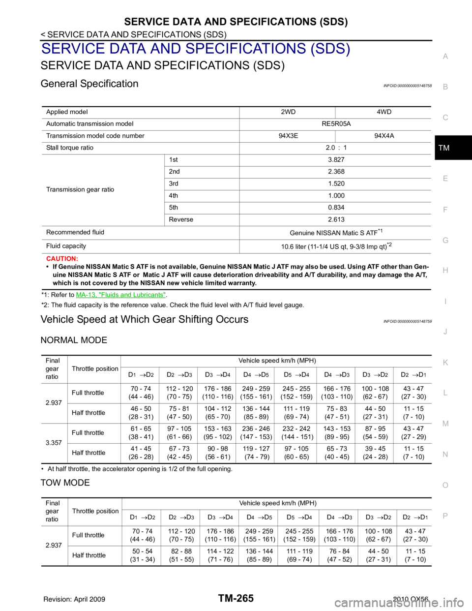
Vehicle Speed at Which Gear Shifting OccursINFOID:0000000005148759
NORMAL MODE
• At half throttle, the accelerator opening is 1/2 of the full opening.
TOW MODE
Applied model 2WD4WD
Automatic transmission model RE5R05A
Transmission model code number 94X3E94X4A
Stall torque ratio 2.0 : 1
Transmission gear ratio 1st
3.827
2nd 2.368
3rd 1.520
4th 1.000
5th 0.834
Reverse 2.613
Recommended fluid Genuine NISSAN Matic S ATF
*1
Fluid capacity10.6 liter (11-1/4 US qt, 9-3/8 Imp qt)*2
CAUTION:
• If Genuine NISSAN Matic S ATF is not available, Genuine NISSAN Matic J ATF may also be used. Using ATF other than Gen-
uine NISSAN Matic S ATF or Matic J ATF will cause deterioration driveability and A/T durability, and may damage the A/T,
which is not covered by the NISSAN new vehicle limited warranty.
Final
gear
ratio Throttle position
Vehicle speed km/h (MPH)
D
1 → D2D2 →D3D3 →D4D4 →D5D5 →D4D4 →D3D3 → D2D2 →D1
2.937 Full throttle
70 - 74
(44 - 46) 112 - 120
(70 - 75) 176 - 186
(110 - 116) 249 - 259
(155 - 161) 245 - 255
(152 - 159) 166 - 176
(103 - 110) 100 - 108
(62 - 67) 43 - 47
(27 - 30)
Half throttle 46 - 50
(28 - 31) 75 - 81
(47 - 50) 104 - 112
(65 - 70) 136 - 144
(85 - 89) 111 - 11 9
(69 - 74) 75 - 83
(47 - 51) 44 - 50
(27 - 31) 11 - 1 5
(7 - 10)
3.357 Full throttle
61 - 65
(38 - 41) 97 - 105
(61 - 66) 153 - 163
(95 - 102) 236 - 246
(147 - 153) 232 - 242
(144 - 151) 143 - 153
(89 - 95) 87 - 95
(54 - 59) 43 - 47
(27 - 29)
Half throttle 41 - 45
(26 - 28) 67 - 73
(42 - 45) 90 - 98
(56 - 61) 11 9 - 1 2 7
(74 - 79) 97 - 105
(60 - 65) 65 - 73
(40 - 45) 39 - 45
(24 - 28) 11 - 1 5
(7 - 10)
Final
gear
ratio Throttle position Vehicle speed km/h (MPH)
D
1 → D2D2 →D3D3 →D4D4 →D5D5 →D4D4 →D3D3 → D2D2 →D1
2.937 Full throttle
70 - 74
(44 - 46) 112 - 120
(70 - 75) 176 - 186
(110 - 116) 249 - 259
(155 - 161) 245 - 255
(152 - 159) 166 - 176
(103 - 110) 100 - 108
(62 - 67) 43 - 47
(27 - 30)
Half throttle 50 - 54
(31 - 34) 82 - 88
(51 - 55) 114 - 122
(71 - 76) 136 - 144
(85 - 89) 111 - 11 9
(69 - 74) 76 - 84
(47 - 52) 44 - 50
(27 - 31) 11 - 1 5
(7 - 10)
Revision: April 20092010 QX56
Page 3961 of 4210

TM-266
< SERVICE DATA AND SPECIFICATIONS (SDS)
SERVICE DATA AND SPECIFICATIONS (SDS)
• At half throttle, the accelerator opening is 1/2 of the full opening.
Vehicle Speed at Which Lock-up Occurs/ReleasesINFOID:0000000005148760
• At closed throttle, the accelerator opening is less than 1/8 condition. (Closed throttle position signal OFF)
• At half throttle, the accelerator opening is 1/2 of the full opening.
Stall SpeedINFOID:0000000005148761
Line PressureINFOID:0000000005148762
Input Speed SensorINFOID:0000000005148763
Output Speed SensorINFOID:0000000005148764
Reverse BrakeINFOID:0000000005148765
3.357Full throttle
61 - 65
(38 - 41) 97 - 105
(61 - 66) 153 - 163
(95 - 102) 236 - 246
(147 - 153) 232 - 242
(144 - 151) 143 - 153
(89 - 95) 87 - 95
(54 - 59) 43 - 47
(27 - 29)
Half throttle 46 - 50
(29 - 31) 73 - 79
(45 - 59) 99 - 107
(62 - 66) 119 - 127
(74 - 79) 97 - 105
(60 - 65) 65 - 73
(40 - 45) 39 - 45
(24 - 28) 11 - 1 5
(7 - 10)
Final gear ratio Throttle position Vehicle speed km/h (MPH)
Lock-up ON Lock-up OFF
2.937 Closed throttle
51 - 59 (32 - 36) 48 - 56 (30 - 34)
Half throttle 177 - 185 (110 - 115) 111 - 119 (69 - 73)
3.357 Closed throttle
44 - 52 (28 - 32) 41 - 49 (26 - 30)
Half throttle 161 - 169 (100 - 105) 97 - 105 (61 - 65)
Stall speed 2,550 - 2,850 rpm
Engine speedLine pressure kPa (kg/cm
2, psi)
“R” position “D” position
At idle speed 425 – 465 (4.3 – 4.7, 62 – 67) 379 – 428 (3.9 – 4.4, 55 – 62)
At stall speed 1,605 – 1,950 (16.4 – 19.9, 233 – 283) 1,310 – 1,500 (13.4 – 15.3, 190 – 218)
Name ConditionData (Approx.)
Input speed sensor 1 When running at 50 km/h (31 MPH) in 4th speed witch the closed throttle position
signal OFF.
1.3 kHz
Input speed sensor 2 When running at 20 km/h (12 MPH) in 1st speed witch the closed throttle position
signal OFF.
Name
ConditionData (Approx.)
Output speed sensor When running at 20 km/h (12 MPH). 185 Hz
Number of drive plates 7
Number of driven plates 7
Clearance mm (in) Standard 0.7 – 1.1 (0.028 – 0.043)
Revision: April 20092010 QX56
Page 3962 of 4210

SERVICE DATA AND SPECIFICATIONS (SDS)TM-267
< SERVICE DATA AND SPECIFICATIONS (SDS)
CEF
G H
I
J
K L
M A
B
TM
N
O P
Total End PlayINFOID:0000000005148766
BEARING RACE FOR ADJUSTING TOTAL END PLAY
Torque ConverterINFOID:0000000005148767
Thickness of retaining plates Thickness mm (in)
4.2 (0.165)
4.4 (0.173)
4.6 (0.181)
4.8 (0.189)
5.0 (0.197)
5.2 (0.205)
5.4 (0.213)
Total end play mm (in) 0.25 – 0.55 (0.0098 – 0.0217)
Thickness mm (in)
0.8 (0.031)
1.0 (0.039)
1.2 (0.047)
1.4 (0.055)
1.6 (0.063)
1.8 (0.071)
Distance between end of converter housing and torque
converter mm (in) 24.0 (0.94)
Revision: April 20092010 QX56