2010 INFINITI QX56 lock
[x] Cancel search: lockPage 2994 of 4210

POWER WINDOW SYSTEMPWC-9
< FUNCTION DIAGNOSIS >
C
DE
F
G H
I
J
L
M A
B
PWC
N
O P
Front power window motor LH • Integrates the ENCODER POWER and WINDOW MOTOR.
• Starts operating with signals from main power window and door lock/unlock switch.
• Transmits power window motor rotation as a pulse signal to main power window and
door lock/unlock switch.
Front power window motor RH Starts operating with signals from main power window and door lock/unlock switch &
power window and door lock/unlock switch RH.
Rear power window motor Starts operating with signals from main power window and door lock/unlock switch &
rear power window switch.
Front door lock assembly LH (key cylin-
der switch) Transmits operation condition of key cylinder switch to power window main switch.
Front door switch LH or RH Detects door open/close condition and transmits to BCM.
Component
Function
Revision: April 20092010 QX56
Page 2995 of 4210

PWC-10
< FUNCTION DIAGNOSIS >
DIAGNOSIS SYSTEM (BCM)
DIAGNOSIS SYSTEM (BCM)
COMMON ITEM
COMMON ITEM : CONSULT-III Function (BCM - COMMON ITEM)INFOID:0000000005369205
APPLICATION ITEM
CONSULT-III performs the following functions via CAN communication with BCM.
SYSTEM APPLICATION
BCM can perform the following functions for each system.
NOTE:
It can perform the diagnosis modes except the following for all sub system selection items.
RETAINED PWR
Diagnosis mode Function Description
WORK SUPPORT Changes the setting for each system function.
SELF-DIAG RESULTS Displays the diagnosis results judged by BCM. Refer to BCS-54, "
DTCIndex".
CAN DIAG SUPPORT MNTR Monitors the reception status of CAN communication viewed from BCM.
DATA MONITOR The BCM input/output signals are displayed.
ACTIVE TEST The signals used to activate each device are forcibly supplied from BCM.
ECU IDENTIFICATION The BCM part number is displayed.
CONFIGURATION • Enables to read and save the vehicle specification.
• Enables to write the vehicle specification when replacing BCM.
System
Sub system selection item Diagnosis mode
WORK SUPPORT DATA MONITOR ACTIVE TEST
BCM BCM ×
Door lock DOOR LOCK ×××
Rear window defogger REAR DEFOGGER ×
Warning chime BUZZER ××
Interior room lamp timer INT LAMP ×××
Remote keyless entry system MULTI REMOTE ENT ××
Exterior lamp HEAD LAMP ×××
Wiper and washer WIPER ×××
Turn signal and hazard warning lamps FLASHER ××
Air conditioner AIR CONDITONER ×
Intelligent Key system INTELLIGENT KEY ×
Combination switch COMB SW ×
Immobilizer IMMU ××
Interior room lamp battery saver BATTERY SAVER ×××
Back door open TRUNK ××
RAP (retained accessory power) RETAINED PWR ×××
Signal buffer system SIGNAL BUFFER ××
TPMS (tire pressure monitoring sys-
tem) AIR PRESSURE MONITOR
×××
Vehicle security system THEFT ALM ×××
Panic alarm system PANIC ALARM ×
Revision: April 20092010 QX56
Page 2997 of 4210
PWC-12
< COMPONENT DIAGNOSIS >
POWER SUPPLY AND GROUND CIRCUIT
COMPONENT DIAGNOSIS
POWER SUPPLY AND GROUND CIRCUIT
POWER WINDOW MAIN SWITCH
POWER WINDOW MAIN SWITCH : DescriptionINFOID:0000000005147171
• BCM supplies power.
• It operates each power window motor via corresponding power window switch and makes window move up/down when main power window and door lock/unlock switch is operated.
POWER WINDOW MAIN SWITCH : Component Function CheckINFOID:0000000005147172
Main Power Window And Door Lock/Unlock Switch
1. CHECK MAIN POWER WINDOW AND DO OR LOCK/UNLOCK SWITCH FUNCTION
Does power window motor operate with main power window and door lock/unlock switch operation?
Is the inspection result normal?
YES >> Main power window and door lock/unlock switch power supply and ground circuit are OK.
NO >> Refer to PWC-12, "
POWER WINDOW MAIN SWITCH : Diagnosis Procedure".
POWER WINDOW MAIN SWITCH : Diagnosis ProcedureINFOID:0000000005147173
Regarding Wiring Diagram information, refer to PWC-53, "Wiring Diagram".
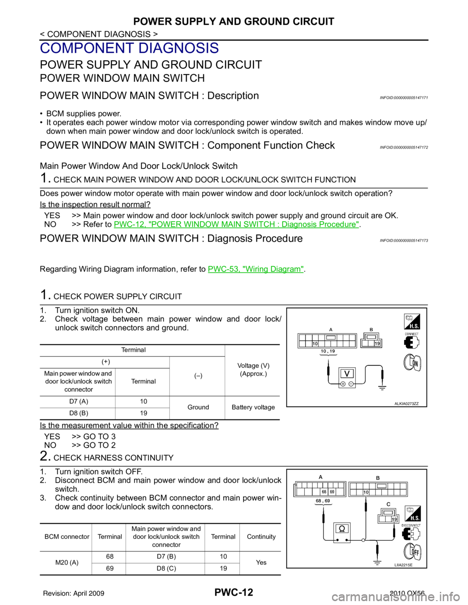
1. CHECK POWER SUPPLY CIRCUIT
1. Turn ignition switch ON.
2. Check voltage between main power window and door lock/ unlock switch connectors and ground.
Is the measurement value within the specification?
YES >> GO TO 3
NO >> GO TO 2
2. CHECK HARNESS CONTINUITY
1. Turn ignition switch OFF.
2. Disconnect BCM and main power window and door lock/unlock switch.
3. Check continuity between BCM connector and main power win- dow and door lock/unlock switch connectors.
Te r m i n a l
Voltage (V)(Approx.)
(+)
(–)
Main power window and
door lock/unlock switch
connector Te r m i n a l
D7 (A) 10
Ground Battery voltage
D8 (B) 19
ALKIA0273ZZ
BCM connector Terminal Main power window and
door lock/unlock switch connector Terminal Continuity
M20 (A) 68
D7 (B) 10
Ye s
69 D8 (C) 19
LIIA2215E
Revision: April 20092010 QX56
Page 2998 of 4210
POWER SUPPLY AND GROUND CIRCUITPWC-13
< COMPONENT DIAGNOSIS >
C
DE
F
G H
I
J
L
M A
B
PWC
N
O P
4. Check continuity between BCM connector and ground.
Is the inspection result normal?
YES >> GO TO 4
NO >> Repair or replace harness.
3. CHECK GROUND CIRCUIT
1. Turn ignition switch OFF.
2. Disconnect main power window and door lock/unlock switch.
3. Check continuity between main power window and door lock/ unlock switch connector and ground.
Is the inspection result normal?
YES >> Replace main power window and door lock/unlock switch. Refer to PWC-117, "
Removal and Installation".
NO >> Repair or replace harness.
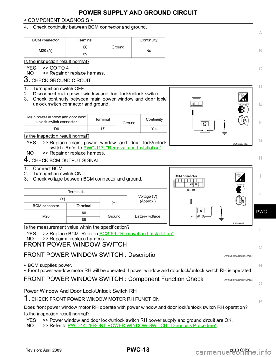
4. CHECK BCM OUTPUT SIGNAL
1. Connect BCM.
2. Turn ignition switch ON.
3. Check voltage between BCM connector and ground.
Is the measurement value within the specification?
YES >> Replace BCM. Refer to BCS-59, "Removal and Installation".
NO >> Repair or replace harness.
FRONT POWER WINDOW SWITCH
FRONT POWER WINDOW SWITCH : DescriptionINFOID:0000000005147174
• BCM supplies power.
• Front power window motor RH will be operated if power window and door lock/unlock switch RH is operated.
FRONT POWER WINDOW SWITCH : Component Function CheckINFOID:0000000005147175
Power Window And Door Lock/Unlock Switch RH
1. CHECK FRONT POWER WINDOW MOTOR RH FUNCTION
Does front power window motor RH operate with power window and door lock/unlock switch RH operation?
Is the inspection result normal?
YES >> Power window and door lock/unlock switch RH power supply and ground circuit are OK.
NO >> Refer to PWC-14, "
FRONT POWER WINDOW SWITCH : Diagnosis Procedure".
BCM connector Terminal
GroundContinuity
M20 (A) 68
No
69
Main power window and door lock/
unlock switch connector Te r m i n a l
GroundContinuity
D8 17 Yes
ALKIA0275ZZ
Te r m i n a l s
Voltage (V)
(Approx.)
(+)
(–)
BCM connector Terminal
M20 68
Ground Battery voltage
69
LIIA0917E
Revision: April 20092010 QX56
Page 2999 of 4210
PWC-14
< COMPONENT DIAGNOSIS >
POWER SUPPLY AND GROUND CIRCUIT
FRONT POWER WINDOW SWIT CH : Diagnosis Procedure
INFOID:0000000005147176
Regarding Wiring Diagram information, refer to PWC-68, "Wiring Diagram".
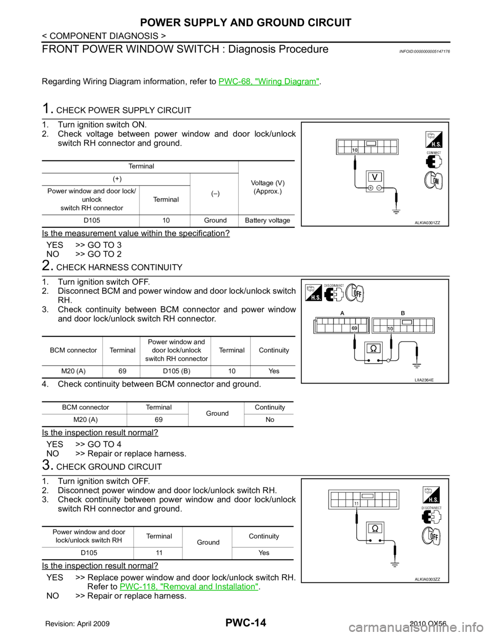
1. CHECK POWER SUPPLY CIRCUIT
1. Turn ignition switch ON.
2. Check voltage between power window and door lock/unlock switch RH connector and ground.
Is the measurement value within the specification?
YES >> GO TO 3
NO >> GO TO 2
2. CHECK HARNESS CONTINUITY
1. Turn ignition switch OFF.
2. Disconnect BCM and power window and door lock/unlock switch RH.
3. Check continuity between BCM connector and power window and door lock/unlock switch RH connector.
4. Check continuity between BCM connector and ground.
Is the inspection result normal?
YES >> GO TO 4
NO >> Repair or replace harness.
3. CHECK GROUND CIRCUIT
1. Turn ignition switch OFF.
2. Disconnect power window and door lock/unlock switch RH.
3. Check continuity between power window and door lock/unlock switch RH connector and ground.
Is the inspection result normal?
YES >> Replace power window and door lock/unlock switch RH. Refer to PWC-118, "
Removal and Installation".
NO >> Repair or replace harness.
Te r m i n a l
Voltage (V)(Approx.)
(+)
(–)
Power window and door lock/
unlock
switch RH connector Te r m i n a l
D105 10Ground Battery voltage
ALKIA0301ZZ
BCM connector Terminal Power window and
door lock/unlock
switch RH connector Terminal Continuity
M20 (A) 69 D105 (B)10 Yes
BCM connector Terminal
GroundContinuity
M20 (A) 69 No
LIIA2364E
Power window and door
lock/unlock switch RH Te r m i n a l
Ground Continuity
D105 11 Yes
ALKIA0303ZZ
Revision: April 20092010 QX56
Page 3000 of 4210

POWER SUPPLY AND GROUND CIRCUITPWC-15
< COMPONENT DIAGNOSIS >
C
DE
F
G H
I
J
L
M A
B
PWC
N
O P
4. CHECK BCM OUTPUT SIGNAL
1. Connect BCM.
2. Turn ignition switch ON.
3. Check voltage between BCM connector and ground.
Is the measurement value within the specification?
YES >> Replace power window and door lock/unlock switch RH.
Refer to PWC-118, "
Removal and Installation".
NO >> Replace BCM. Refer to BCS-59, "
Removal and Installation".
REAR POWER WINDOW SWITCH
REAR POWER WINDOW SWITCH : DescriptionINFOID:0000000005147177
• BCM supplies power.
• Rear power window motor will be operated if rear power window switch is operated. Rear power window\
switch.
REAR POWER WINDOW SWITCH : Component Function CheckINFOID:0000000005147178
Rear Power Window Switch
1. CHECK REAR POWER WINDOW MOTOR FUNCTION
Does rear power window motor operate with rear power window switch operation?
Is the inspection result normal?
YES >> Rear power window switch power supply and ground circuit are OK.
NO >> Refer to PWC-15, "
REAR POWER WINDOW SWITCH : Diagnosis Procedure".
REAR POWER WINDOW SWITCH : Diagnosis ProcedureINFOID:0000000005147179
Regarding Wiring Diagram information, refer to PWC-53, "Wiring Diagram".
1. CHECK POWER WINDOW POWER SUPPLY CIRCUIT
1. Turn ignition switch OFF.
2. Disconnect rear power window switch LH or RH.
3. Turn ignition switch ON.
4. Check voltage between rear power window switch LH or RH connector D203 (LH), D303 (RH) terminals 2, 3 and ground.
Is the inspection result normal?
YES >> GO TO 2
NO >> Repair or replace harness.
2. CHECK POWER WINDOW GROUND CIRCUIT
Te r m i n a l s Voltage (V)
(Approx.)
(+)
(-)
BCM connector Terminal
M20 69Ground Ba ttery voltage
WIIA0508E
2 - Ground : Battery voltage
3 - Ground : Battery voltage
LIIA1348E
Revision: April 20092010 QX56
Page 3002 of 4210
POWER WINDOW MOTORPWC-17
< COMPONENT DIAGNOSIS >
C
DE
F
G H
I
J
L
M A
B
PWC
N
O P
POWER WINDOW MOTOR
DRIVER SIDE
DRIVER SIDE : DescriptionINFOID:0000000005147181
Door glass moves UP/DOWN by receiving the signal from power window main switch.
DRIVER SIDE : Componen t Function CheckINFOID:0000000005147182
1. CHECK POWER WINDOW MOTOR CIRCUIT
Does front power window motor LH operate with operating main power window and door lock/unlock switch?
Is the inspection result normal?
YES >> Front power window motor LH is OK.
NO >> Refer to PWC-17, "
DRIVER SIDE : Diagnosis Procedure".
DRIVER SIDE : Diag nosis ProcedureINFOID:0000000005147183
Regarding Wiring Diagram information, refer to PWC-53, "Wiring Diagram".
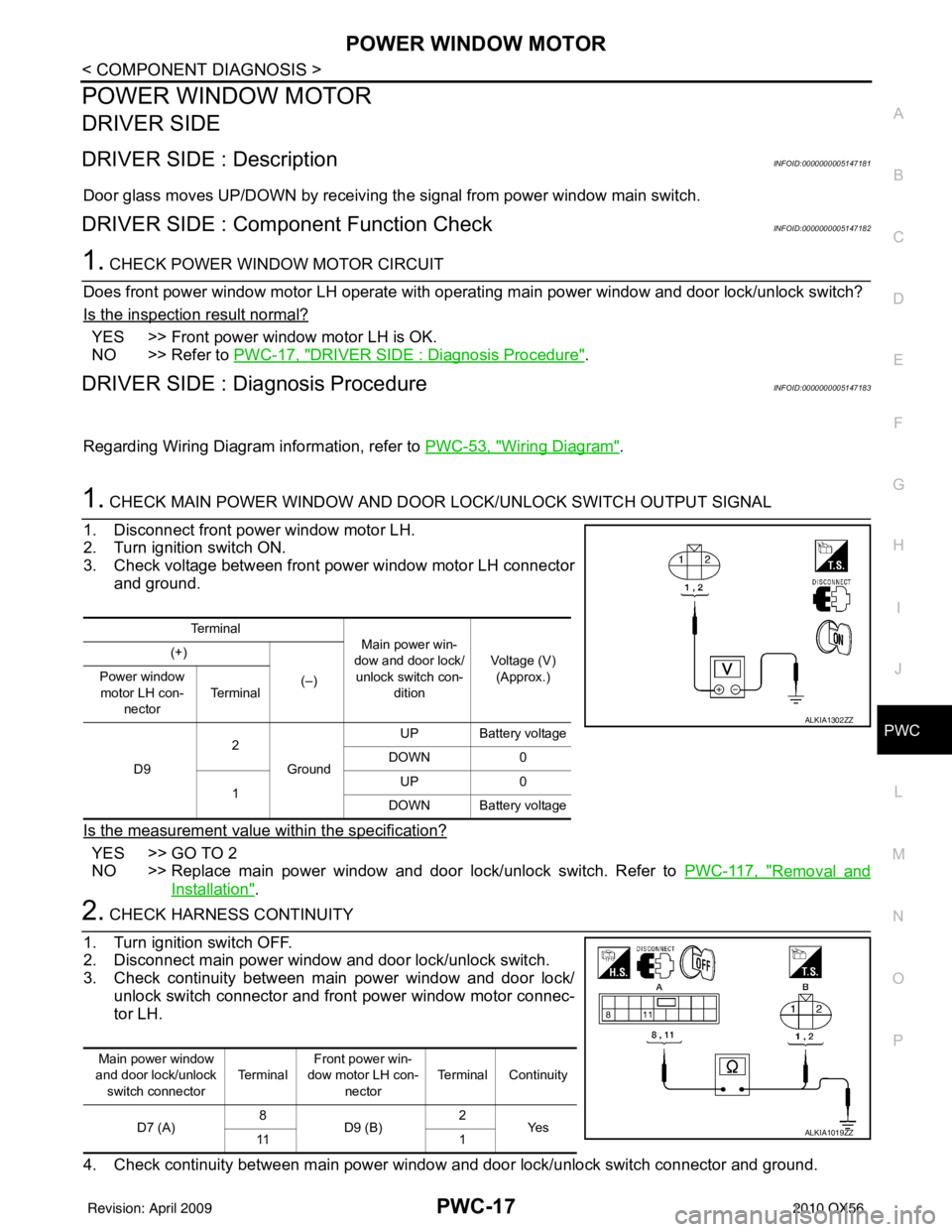
1. CHECK MAIN POWER WINDOW AND DOOR LOCK/UNLOCK SWITCH OUTPUT SIGNAL
1. Disconnect front power window motor LH.
2. Turn ignition switch ON.
3. Check voltage between front power window motor LH connector and ground.
Is the measurement value within the specification?
YES >> GO TO 2
NO >> Replace main power window and door lock/unlock switch. Refer to PWC-117, "
Removal and
Installation".
2. CHECK HARNESS CONTINUITY
1. Turn ignition switch OFF.
2. Disconnect main power window and door lock/unlock switch.
3. Check continuity between main power window and door lock/ unlock switch connector and front power window motor connec-
tor LH.
4. Check continuity between main power window and door lock/unlock switch connector and ground.
Te r m i n a l Main power win-
dow and door lock/
unlock switch con- dition Voltage (V)
(Approx.)
(+)
(–)
Power window
motor LH con- nector Te r m i n a l
D9 2
Ground UP Battery voltage
DOWN 0
1 UP
0
DOWN Battery voltage
ALKIA1302ZZ
Main power window
and door lock/unlock switch connector Te r m i n a lFront power win-
dow motor LH con- nector Terminal Continuity
D7 (A) 8
D9 (B) 2
Ye s
11 1
ALKIA1019ZZ
Revision: April 20092010 QX56
Page 3003 of 4210
PWC-18
< COMPONENT DIAGNOSIS >
POWER WINDOW MOTOR
Is the inspection result normal?
YES >> GO TO 3
NO >> Repair or replace harness.
3. CHECK POWER WINDOW MOTOR
Check front power window motor LH.
Refer to PWC-18, "
DRIVER SIDE : Component Inspection".
Is the inspection result normal?
YES >> Check intermittent incident. Refer to GI-38, "Intermittent Incident".
NO >> Replace power window motor LH. Refer to GW-15, "
Removal and Installation".
DRIVER SIDE : Component InspectionINFOID:0000000005147184
COMPONENT INSPECTION
1. CHECK FRONT POWER WINDOW MOTOR LH
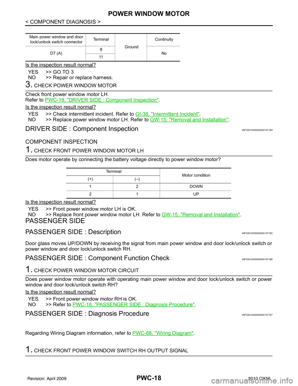
Does motor operate by connecting the battery voltage directly to power window motor?
Is the inspection result normal?
YES >> Front power window motor LH is OK.
NO >> Replace front power window motor LH. Refer to GW-15, "
Removal and Installation".
PASSENGER SIDE
PASSENGER SIDE : DescriptionINFOID:0000000005147185
Door glass moves UP/DOWN by receiving the signal from main power window and door lock/unlock switch or
power window and door lock/unlock switch RH.
PASSENGER SIDE : Component Function CheckINFOID:0000000005147186
1. CHECK POWER WINDOW MOTOR CIRCUIT
Does power window motor operate with operating main power window and door lock/unlock switch or power
window and door lock/unlock switch RH?
Is the inspection result normal?
YES >> Front power window motor RH is OK.
NO >> Refer to PWC-18, "
PASSENGER SIDE : Diagnosis Procedure".
PASSENGER SIDE : Diagnosis ProcedureINFOID:0000000005147187
Regarding Wiring Diagram information, refer to PWC-68, "Wiring Diagram".
1. CHECK FRONT POWER WINDOW SWITCH RH OUTPUT SIGNAL
Main power window and door
lock/unlock switch connector Te r m i n a l
GroundContinuity
D7 (A) 8
No
11
Te r m i n a l Motor condition
(+) (–)
12 D OW N
21 U P
Revision: April 20092010 QX56