2010 INFINITI QX56 warning light
[x] Cancel search: warning lightPage 2086 of 4210

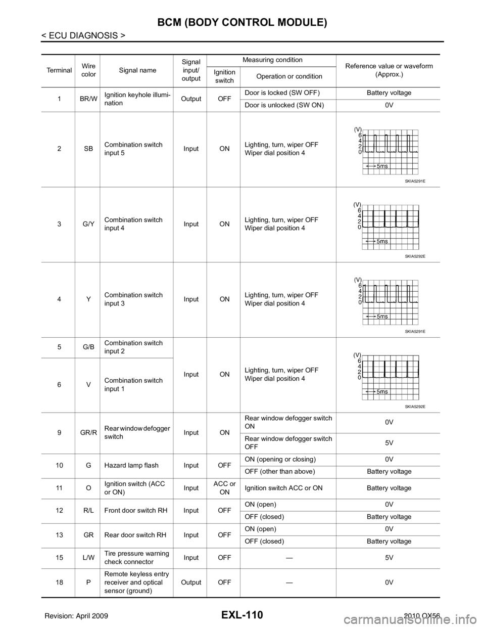
EXL-110
< ECU DIAGNOSIS >
BCM (BODY CONTROL MODULE)
Te r m i n a lWire
color Signal name Signal
input/
output Measuring condition
Reference value or waveform
(Approx.)
Ignition
switch Operation or condition
1BR/W Ignition keyhole illumi-
nation Output OFFDoor is locked (SW OFF)
Battery voltage
Door is unlocked (SW ON) 0V
2SB Combination switch
input 5 Input ON
Lighting, turn, wiper OFF
Wiper dial position 4
3G/Y Combination switch
input 4 Input ONLighting, turn, wiper OFF
Wiper dial position 4
4Y Combination switch
input 3 Input ON
Lighting, turn, wiper OFF
Wiper dial position 4
5G/B Combination switch
input 2
Input ONLighting, turn, wiper OFF
Wiper dial position 4
6V Combination switch
input 1
9GR/R Rear window defogger
switch
Input ONRear window defogger switch
ON
0V
Rear window defogger switch
OFF 5V
10 G Hazard lamp flash Input OFF ON (opening or closing)
0V
OFF (other than above) Battery voltage
11 O Ignition switch (ACC
or ON)
InputACC or
ON Ignition switch ACC or ON
Battery voltage
12 R/L Front door switch RH Input OFF ON (open)
0V
OFF (closed) Battery voltage
13 GR Rear door switch RH Input OFF ON (open)
0V
OFF (closed) Battery voltage
15 L/W Tire pressure warning
check connector
Input OFF
—5V
18 P Remote keyless entry
receiver and optical
sensor (ground)
Output OFF
—0V
SKIA5291E
SKIA5292E
SKIA5291E
SKIA5292E
Revision: April 20092010 QX56
Page 2531 of 4210

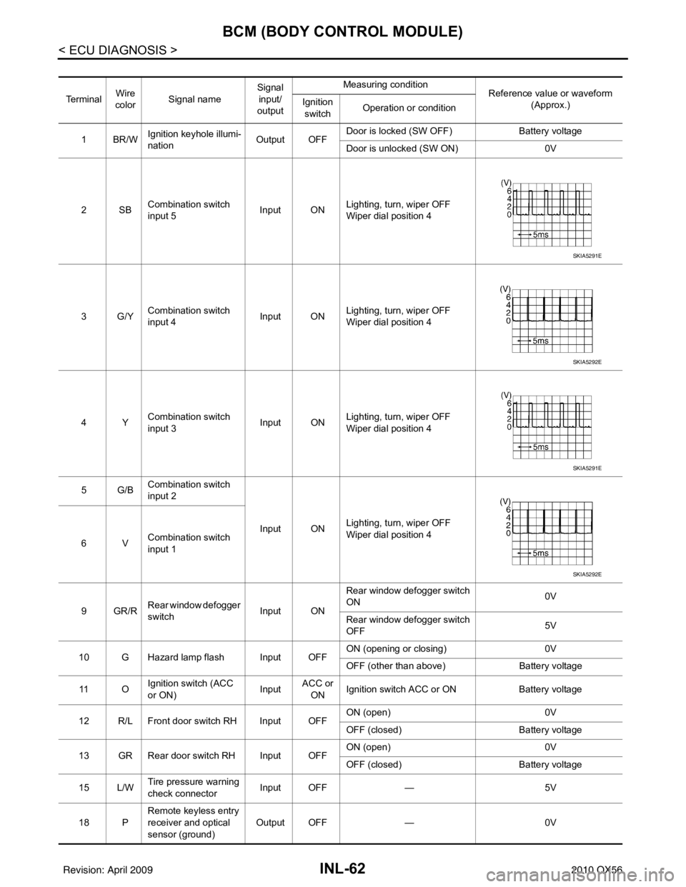
INL-62
< ECU DIAGNOSIS >
BCM (BODY CONTROL MODULE)
Te r m i n a lWire
color Signal name Signal
input/
output Measuring condition
Reference value or waveform
(Approx.)
Ignition
switch Operation or condition
1BR/W Ignition keyhole illumi-
nation Output OFFDoor is locked (SW OFF)
Battery voltage
Door is unlocked (SW ON) 0V
2SB Combination switch
input 5 Input ON
Lighting, turn, wiper OFF
Wiper dial position 4
3G/Y Combination switch
input 4 Input ONLighting, turn, wiper OFF
Wiper dial position 4
4Y Combination switch
input 3 Input ON
Lighting, turn, wiper OFF
Wiper dial position 4
5G/B Combination switch
input 2
Input ONLighting, turn, wiper OFF
Wiper dial position 4
6V Combination switch
input 1
9GR/R Rear window defogger
switch
Input ONRear window defogger switch
ON
0V
Rear window defogger switch
OFF 5V
10 G Hazard lamp flash Input OFF ON (opening or closing)
0V
OFF (other than above) Battery voltage
11 O Ignition switch (ACC
or ON)
InputACC or
ON Ignition switch ACC or ON
Battery voltage
12 R/L Front door switch RH Input OFF ON (open)
0V
OFF (closed) Battery voltage
13 GR Rear door switch RH Input OFF ON (open)
0V
OFF (closed) Battery voltage
15 L/W Tire pressure warning
check connector
Input OFF
—5V
18 P Remote keyless entry
receiver and optical
sensor (ground)
Output OFF
—0V
SKIA5291E
SKIA5292E
SKIA5291E
SKIA5292E
Revision: April 20092010 QX56
Page 2643 of 4210
![INFINITI QX56 2010 Factory Service Manual LAN
CAN COMMUNICATION SYSTEMLAN-45
< FUNCTION DIAGNOSIS > [CAN]
C
D
E
F
G H
I
J
K L
B A
O P
N
Engine speed signal
T RRR R R R R R
Engine status signal TR
Fuel consumption monitor signal TR
RT
ICC stee INFINITI QX56 2010 Factory Service Manual LAN
CAN COMMUNICATION SYSTEMLAN-45
< FUNCTION DIAGNOSIS > [CAN]
C
D
E
F
G H
I
J
K L
B A
O P
N
Engine speed signal
T RRR R R R R R
Engine status signal TR
Fuel consumption monitor signal TR
RT
ICC stee](/manual-img/42/57032/w960_57032-2642.png)
LAN
CAN COMMUNICATION SYSTEMLAN-45
< FUNCTION DIAGNOSIS > [CAN]
C
D
E
F
G H
I
J
K L
B A
O P
N
Engine speed signal
T RRR R R R R R
Engine status signal TR
Fuel consumption monitor signal TR
RT
ICC steering switch signal TR
Malfunction indicator lamp signal T R
Wide open throttle position signal T R
A/T CHECK indicato r lamp signal T R
A/T fluid temperature sensor signal T R
A/T position indicator lamp signal TR RR
A/T self-diagnosis signal R T
Current gear position signal TR R
Input speed signal R TR
Output shaft revolution signal R TR R
P range signal TR R RR
ICC sensor signal T R
Buzzer output signal TR
TR
ICC OD cancel request signal R RT
ICC operation signal R RT
ICC system display signal TR
System setting signal TRT
RTR
A/C switch/indicator signal TR
RT
A/C switch signal RT R
Blower fan motor switch signal RT
Day time running light request signal TR R
Door lock/unlock status signal TR
Door switch signal R R TR R R
Front fog light request signal TR
Front wiper request signal RT R
High beam request signal TR R
Horn chirp signal TR
Ignition switch signal RTR R
Key fob door unlock signal RT
Key fob ID signal RT
Key switch signal RT
Low beam request signal TR
Position light request signal TR R
Rear window defogger switch signal T RR
Sleep wake up signal RT R R
Theft warning horn request signal TR
Signal name/Connecting unit
ECM
TCM
LASER ICC
ADP AV
BCM
HVAC I-KEY M&A
STRG 4WD
ABS
IPDM-E
Revision: April 20092010 QX56
Page 2787 of 4210

MWI
DIAGNOSIS SYSTEM (METER)MWI-25
< FUNCTION DIAGNOSIS >
C
DE
F
G H
I
J
K L
M B A
O P
NOTE:
Some items are not available due to vehicle specification.
*: The monitor will indicate “OFF” even though the brake warnin g lamp is on if either of the following conditions exist.
• The parking brake is engaged
• The brake fluid level is low CRUISE W/L [ON/OFF]
X Indicates [ON/OFF] condition of CRUISE warning lamp.
4WD LOCK SW [ON/OFF] X Indicates [ON/OFF] condition of 4WD lock switch.
4WD LOCK IND [ON/OFF] X Indicates [ON/OFF] condition of 4WD lock indicator.
SEAT BELT W/L [ON/OFF] X Indicates [ON/OFF] condition of seat belt warning lamp.
LIGHT IND [ON/OFF] X Indicates [ON/OFF] condition of light indicator.
4WD W/L [ON/OFF] X Indicates [ON/OFF] condition of 4WD warning lamp.
Display item [Unit]
MAIN
SIGNALS SELECTION
FROM MENU Description
Revision: April 20092010 QX56
Page 2821 of 4210

MWI
COMBINATION METERMWI-59
< ECU DIAGNOSIS >
C
DE
F
G H
I
J
K L
M B A
O P
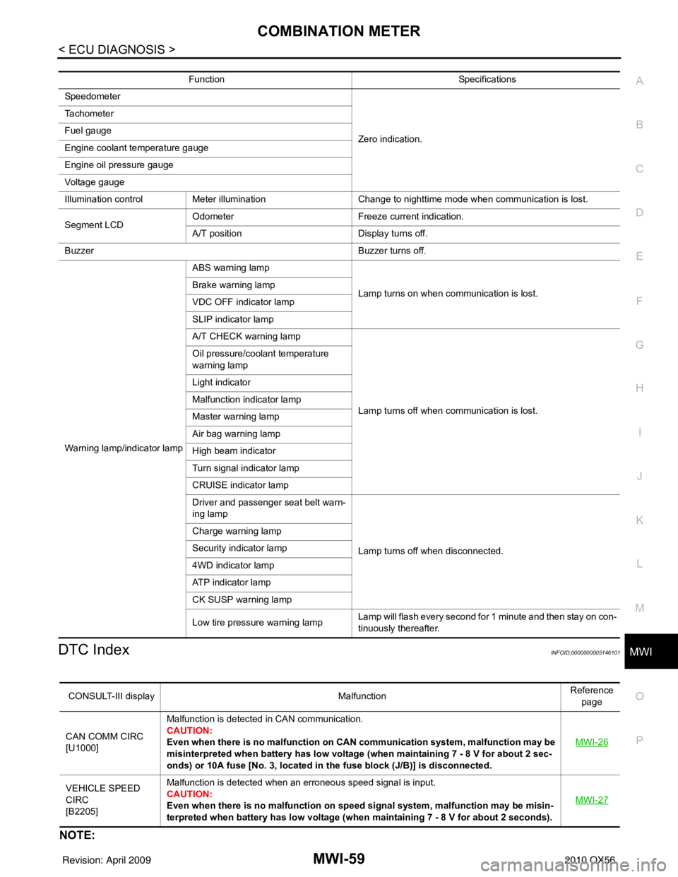
DTC IndexINFOID:0000000005146101
NOTE:
Function Specifications
Speedometer
Zero indication.
Tachometer
Fuel gauge
Engine coolant temperature gauge
Engine oil pressure gauge
Voltage gauge
Illumination control
Meter illumination Change to nighttime mode when communication is lost.
Segment LCD Odometer
Freeze current indication.
A/T position Display turns off.
Buzzer Buzzer turns off.
Warning lamp/indicator lamp ABS warning lamp
Lamp turns on when communication is lost.
Brake warning lamp
VDC OFF indicator lamp
SLIP indicator lamp
A/T CHECK warning lamp
Lamp turns off when communication is lost.
Oil pressure/coolant temperature
warning lamp
Light indicator
Malfunction indicator lamp
Master warning lamp
Air bag warning lamp
High beam indicator
Turn signal indicator lamp
CRUISE indicator lamp
Driver and passenger seat belt warn-
ing lamp
Lamp turns off when disconnected.
Charge warning lamp
Security indicator lamp
4WD indicator lamp
ATP indicator lamp
CK SUSP warning lamp
Low tire pressu
re warning lamp Lamp will flash every second for 1 minute and then stay on con-
tinuously thereafter.
CONSULT-III display
MalfunctionReference
page
CAN COMM CIRC
[U1000] Malfunction is detected in CAN communication.
CAUTION:
Even when there is no ma
lfunction on CAN communication system, malfunction may be
misinterpreted when battery has low voltag e (when maintaining 7 - 8 V for about 2 sec-
onds) or 10A fuse [No. 3, located in the fuse block (J/B)] is disconnected. MWI-26
VEHICLE SPEED
CIRC
[B2205]Malfunction is detected when an erroneous speed signal is input.
CAUTION:
Even when there is no malfunction on speed signal system, malfunction may be misin-
terpreted when battery has low voltage (whe
n maintaining 7 - 8 V for about 2 seconds). MWI-27
Revision: April 20092010 QX56
Page 2827 of 4210

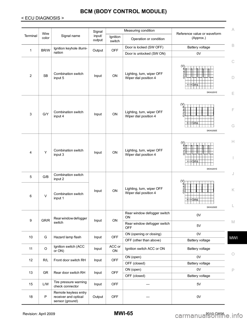
MWI
BCM (BODY CONTROL MODULE)MWI-65
< ECU DIAGNOSIS >
C
DE
F
G H
I
J
K L
M B A
O P
Te r m i n a l Wire
color Signal name Signal
input/
output Measuring condition
Reference value or waveform
(Approx.)
Ignition
switch Operation or condition
1BR/W Ignition keyhole illumi-
nation Output OFFDoor is locked (SW OFF)
Battery voltage
Door is unlocked (SW ON) 0V
2SB Combination switch
input 5 Input ON
Lighting, turn, wiper OFF
Wiper dial position 4
3G/Y Combination switch
input 4 Input ONLighting, turn, wiper OFF
Wiper dial position 4
4Y Combination switch
input 3 Input ON
Lighting, turn, wiper OFF
Wiper dial position 4
5G/B Combination switch
input 2
Input ONLighting, turn, wiper OFF
Wiper dial position 4
6V Combination switch
input 1
9GR/R Rear window defogger
switch
Input ONRear window defogger switch
ON
0V
Rear window defogger switch
OFF 5V
10 G Hazard lamp flash Input OFF ON (opening or closing)
0V
OFF (other than above) Battery voltage
11 O Ignition switch (ACC
or ON)
InputACC or
ON Ignition switch ACC or ON
Battery voltage
12 R/L Front door switch RH Input OFF ON (open)
0V
OFF (closed) Battery voltage
13 GR Rear door switch RH Input OFF ON (open)
0V
OFF (closed) Battery voltage
15 L/W Tire pressure warning
check connector
Input OFF
—5V
18 P Remote keyless entry
receiver and optical
sensor (ground)
Output OFF
—0V
SKIA5291E
SKIA5292E
SKIA5291E
SKIA5292E
Revision: April 20092010 QX56
Page 2890 of 4210
![INFINITI QX56 2010 Factory Service Manual PCS
DIAGNOSIS SYSTEM (IPDM E/R)PCS-15
< FUNCTION DIAGNOSIS > [IPDM E/R]
C
D
E
F
G H
I
J
K L
B A
O P
N
ACTIVE TEST
Te s t i t e m
TAIL&CLR REQ
[OFF/ON]
×Displays the status of the position light requ INFINITI QX56 2010 Factory Service Manual PCS
DIAGNOSIS SYSTEM (IPDM E/R)PCS-15
< FUNCTION DIAGNOSIS > [IPDM E/R]
C
D
E
F
G H
I
J
K L
B A
O P
N
ACTIVE TEST
Te s t i t e m
TAIL&CLR REQ
[OFF/ON]
×Displays the status of the position light requ](/manual-img/42/57032/w960_57032-2889.png)
PCS
DIAGNOSIS SYSTEM (IPDM E/R)PCS-15
< FUNCTION DIAGNOSIS > [IPDM E/R]
C
D
E
F
G H
I
J
K L
B A
O P
N
ACTIVE TEST
Te s t i t e m
TAIL&CLR REQ
[OFF/ON]
×Displays the status of the position light request signal received from BCM via CAN
communication.
HL LO REQ
[OFF/ON] ×
Displays the status of the low beam request signal received from BCM via CAN
communication.
HL HI REQ
[OFF/ON] ×Displays the status of the high beam request signal received from BCM via CAN
communication.
FR FOG REQ
[OFF/ON] ×Displays the status of the front fog lamp request signal received from BCM via
CAN communication.
FR WIP REQ
[STOP/1LOW/LOW/HI] ×
Displays the status of the front wiper request signal received from BCM via CAN
communication.
WIP AUTO STOP
[STOP P/ACT P] ×
Displays the status of the front wiper auto stop signal judged by IPDM E/R.
WIP PROT
[OFF/Block] ×
Displays the status of the front wiper fail-safe operation judged by IPDM E/R.
ST RLY REQ
[OFF/ON] Displays the status of the starter request signal received from ECM via CAN com-
munication.
IGN RLY
[OFF/ON] ×
Displays the status of the ignition relay judged by IPDM E/R.
RR DEF REQ
[OFF/ON] ×Displays the status of the rear defogger request signal received from AV control
unit via CAN communication.
OIL P SW
[OPEN/CLOSE] Displays the status of the oil pressure switch judged by IPDM E/R.
DTRL REQ
[OFF] Displays the status of the daytime light request signal received from BCM via CAN
communication.
HOOD SW
[OPEN/CLOSE] Displays the status of the hood switch judged by IPDM E/R.
THFT HRN REQ
[OFF/ON] Displays the status of the theft warning horn request signal received from BCM
via CAN communication.
HORN CHIRP
[OFF/ON] Displays the status of the horn reminder signal received from BCM via CAN com-
munication.
Monitor Item
[Unit] MAIN SIG-
NALS Description
Test item
Operation Description
REAR DEFOGGER OFF
OFF
ON Operates rear window defogger relay.
FRONT WIPER OFF
OFF
LO Operates the front wiper relay.
HI Operates the front wiper relay and front wiper high relay.
MOTOR FAN 1O
FF
2O FF
3 Operates the cooling fan relay.
4 Operates the cooling fan relay.
Revision: April 20092010 QX56
Page 2956 of 4210

PG-46
< COMPONENT DIAGNOSIS >
HARNESS
D4 E6 B/8: Front combination lamp LH (with
daytime light system) C1 E119 W/16: IPDM E/R (intelligent power distribution
module engine room)
C2 E7 GR/2 : Fusible link box (battery) D1 E120 W/6: IPDM E/R (intelligent power distribution
module engine room)
C2 E9 — : Body ground E1 E121 BR/12: IPDM E/R (intelligent power distribution
module engine room)
D4 E11 B/8 : Front combination lamp LH (without
daytime light system) C1 E122 W/12: IPDM E/R (intelligent power distribution
module engine room)
D3 E12 B/5 : Stop lamp relay D1 E123 BR/8: IPDM E/R (intelligent power distribution
module engine room)
B2 E13 W/2 : Hood switch D1 E124 B/6: IPDM E/R (intelligent power distribution
module engine room)
D4 E14 — : Body ground F3 E125 B/47: ABS actuator and electric unit
(control unit)
C2 E15 — : Body ground D4 E126 — : Body ground
C1 E16 B/40 : ECM C2 E130 W/2 : Compressor motor relay
E4 E18 GR/2 : Front wheel sensor LH C3 E131 W/2 : Compressor motor relay
D1 E19 W/16 : To F33 D1 E134 GR/6 : ICC brake hold relay
E3 E21 GR/2 : Brake fluid level switch C2 E135 GR/2 : Transfer dropping resistor
E2 E23 GR/6 : Front wiper motor C1 E140 BR/6 : Trailer tow relay 2
D4 E24 — : Body ground B2 E153 W/2 : Transfer motor relay
F3 E25 BR/3 : Intelligent key warning buzzer B2 E154 W/2 : Transfer motor relay
C3 E27 BR/2 : Fusible link box (battery )D3 E156 L/4 : Trailer turn relay LH
C2 E30 /1 : Fusible link box (battery) D3 E157 L/4 : Trailer turn relay RH
E3 E31 B/3 : Front pressure sensor D5 E158 B/3 : Front sonar sensor LH outer
E3 E32 B/3 : Rear pressure sensor D5 E159 GR/3 : To E164
E1 E39 W/2 : To F34 B4 E160 GR/3 : To E165
D3 E40 B/3 : To E201 C3 E161 B/3 : Battery current sensor
D3 E41 SMJ : To C1 B4 E162 B/3 : Front sonar sensor LH inner
A4 E42 B/6 : ICC sensor C5 E163 B/3 : Front sonar sensor RH inner
E1 E46 B/5 : Transfer shift high relay D5 E164 GR/3 : To E159
D2 E47 B/5 : Transfer shift low relay A4 E165 GR/3 : To E160
C4 E48 B/3 : Refrigerant pressure sensor A3 E166 B/3 : Front sonar sensor RH outer
E3 E49 B/6 : Active booster Engine room sub-harness
D1 E69 L/4 : Transfer shut off relay D3 E201 B/3 : To E40
D5 E101 B/3 : Front turn/fog lamp LH C1 E202 /1 : Fusible link box (battery)
A4 E102 B/3 : Front turn/fog lamp RH C2 E203 — : Engine ground
C3 E103 B/5 : Daytime light relay C3 E204 /1 : Generator
D4 E105 BR/2 : Front and rear washer motor C3 E205 B/3 : Generator
E4 E106 BR/2 : Washer fluid level switch C3 E206 /1 : Generator
B3 E107 B/8 : Front combination lamp RH (without
daytime light system)
A3 E108 B/6 : Front combination lamp RH (with
daytime light system)
Revision: April 20092010 QX56