2010 INFINITI QX56 key fob
[x] Cancel search: key fobPage 1065 of 4210
![INFINITI QX56 2010 Factory Service Manual PREPARATIONDLK-231
< PREPARATION > [WITH INTELLIGENT KEY SYSTEM]
C
D
E
F
G H
I
J
L
M A
B
DLK
N
O P
PREPARATION
PREPARATION
Special Service ToolINFOID:0000000005147048
The actual shapes of Kent-Moore t INFINITI QX56 2010 Factory Service Manual PREPARATIONDLK-231
< PREPARATION > [WITH INTELLIGENT KEY SYSTEM]
C
D
E
F
G H
I
J
L
M A
B
DLK
N
O P
PREPARATION
PREPARATION
Special Service ToolINFOID:0000000005147048
The actual shapes of Kent-Moore t](/manual-img/42/57032/w960_57032-1064.png)
PREPARATIONDLK-231
< PREPARATION > [WITH INTELLIGENT KEY SYSTEM]
C
D
E
F
G H
I
J
L
M A
B
DLK
N
O P
PREPARATION
PREPARATION
Special Service ToolINFOID:0000000005147048
The actual shapes of Kent-Moore tools may differ from those of special service tools illustrated here.
Tool number
(Kent-Moore No.)
Tool name Description
—
(J-39570)
Chassis ear Locating the noise
—
(J-43980)
NISSAN Squeak and Rat-
tle Kit Repairing the cause of noise
—
(J-43241)
Remote Keyless Entry
Te s t e r Used to test keyfobs
SIIA0993E
SIIA0994E
LEL946A
Revision: April 20092010 QX56
Page 2087 of 4210
BCM (BODY CONTROL MODULE)EXL-111
< ECU DIAGNOSIS >
C
DE
F
G H
I
J
K
M A
B
EXL
N
O P
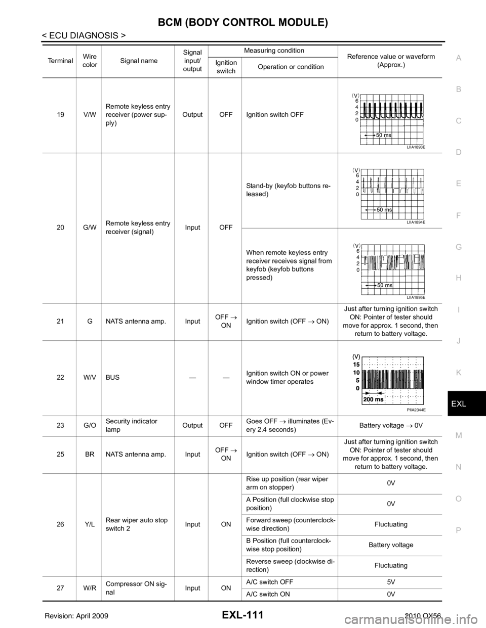
19 V/W Remote keyless entry
receiver (power sup-
ply) Output OFF Ignition switch OFF
20 G/W Remote keyless entry
receiver (signal) Input OFFStand-by (keyfob buttons re-
leased)
When remote keyless entry
receiver receives signal from
keyfob (keyfob buttons
pressed)
21 G NATS antenna amp. Input OFF
→
ON Ignition switch (OFF → ON) Just after turning ignition switch
ON: Pointer of tester should
move for approx. 1 second, then return to battery voltage.
22 W/V BUS — —Ignition switch ON or power
window timer operates
23 G/O Security indicator
lamp Output OFF
Goes OFF
→ illuminates (Ev-
ery 2.4 seconds) Battery voltage
→ 0V
25 BR NATS antenna amp. Input OFF
→
ON Ignition switch (OFF → ON) Just after turning ignition switch
ON: Pointer of tester should
move for approx. 1 second, then return to battery voltage.
26 Y/L Rear wiper auto stop
switch 2 Input ONRise up position (rear wiper
arm on stopper)
0V
A Position (full clockwise stop
position) 0V
Forward sweep (counterclock-
wise direction) Fluctuating
B Position (full counterclock-
wise stop position) Battery voltage
Reverse sweep (clockwise di-
rection) Fluctuating
27 W/R Compressor ON sig-
nal Input ONA/C switch OFF
5V
A/C switch ON 0V
Te r m i n a l
Wire
color Signal name Signal
input/
output Measuring condition
Reference value or waveform
(Approx.)
Ignition
switch Operation or condition
LIIA1893E
LIIA1894E
LIIA1895E
PIIA2344E
Revision: April 20092010 QX56
Page 2532 of 4210
BCM (BODY CONTROL MODULE)INL-63
< ECU DIAGNOSIS >
C
DE
F
G H
I
J
K
M A
B
INL
N
O P
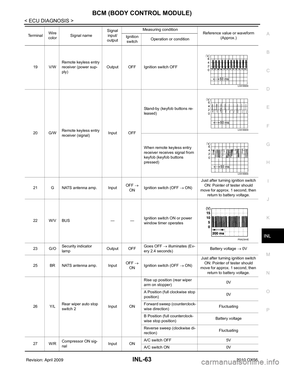
19 V/W Remote keyless entry
receiver (power sup-
ply) Output OFF Ignition switch OFF
20 G/W Remote keyless entry
receiver (signal) Input OFFStand-by (keyfob buttons re-
leased)
When remote keyless entry
receiver receives signal from
keyfob (keyfob buttons
pressed)
21 G NATS antenna amp. Input OFF
→
ON Ignition switch (OFF → ON) Just after turning ignition switch
ON: Pointer of tester should
move for approx. 1 second, then return to battery voltage.
22 W/V BUS — —Ignition switch ON or power
window timer operates
23 G/O Security indicator
lamp Output OFF
Goes OFF
→ illuminates (Ev-
ery 2.4 seconds) Battery voltage
→ 0V
25 BR NATS antenna amp. Input OFF
→
ON Ignition switch (OFF → ON) Just after turning ignition switch
ON: Pointer of tester should
move for approx. 1 second, then return to battery voltage.
26 Y/L Rear wiper auto stop
switch 2 Input ONRise up position (rear wiper
arm on stopper)
0V
A Position (full clockwise stop
position) 0V
Forward sweep (counterclock-
wise direction) Fluctuating
B Position (full counterclock-
wise stop position) Battery voltage
Reverse sweep (clockwise di-
rection) Fluctuating
27 W/R Compressor ON sig-
nal Input ONA/C switch OFF
5V
A/C switch ON 0V
Te r m i n a l
Wire
color Signal name Signal
input/
output Measuring condition
Reference value or waveform
(Approx.)
Ignition
switch Operation or condition
LIIA1893E
LIIA1894E
LIIA1895E
PIIA2344E
Revision: April 20092010 QX56
Page 2643 of 4210
![INFINITI QX56 2010 Factory Service Manual LAN
CAN COMMUNICATION SYSTEMLAN-45
< FUNCTION DIAGNOSIS > [CAN]
C
D
E
F
G H
I
J
K L
B A
O P
N
Engine speed signal
T RRR R R R R R
Engine status signal TR
Fuel consumption monitor signal TR
RT
ICC stee INFINITI QX56 2010 Factory Service Manual LAN
CAN COMMUNICATION SYSTEMLAN-45
< FUNCTION DIAGNOSIS > [CAN]
C
D
E
F
G H
I
J
K L
B A
O P
N
Engine speed signal
T RRR R R R R R
Engine status signal TR
Fuel consumption monitor signal TR
RT
ICC stee](/manual-img/42/57032/w960_57032-2642.png)
LAN
CAN COMMUNICATION SYSTEMLAN-45
< FUNCTION DIAGNOSIS > [CAN]
C
D
E
F
G H
I
J
K L
B A
O P
N
Engine speed signal
T RRR R R R R R
Engine status signal TR
Fuel consumption monitor signal TR
RT
ICC steering switch signal TR
Malfunction indicator lamp signal T R
Wide open throttle position signal T R
A/T CHECK indicato r lamp signal T R
A/T fluid temperature sensor signal T R
A/T position indicator lamp signal TR RR
A/T self-diagnosis signal R T
Current gear position signal TR R
Input speed signal R TR
Output shaft revolution signal R TR R
P range signal TR R RR
ICC sensor signal T R
Buzzer output signal TR
TR
ICC OD cancel request signal R RT
ICC operation signal R RT
ICC system display signal TR
System setting signal TRT
RTR
A/C switch/indicator signal TR
RT
A/C switch signal RT R
Blower fan motor switch signal RT
Day time running light request signal TR R
Door lock/unlock status signal TR
Door switch signal R R TR R R
Front fog light request signal TR
Front wiper request signal RT R
High beam request signal TR R
Horn chirp signal TR
Ignition switch signal RTR R
Key fob door unlock signal RT
Key fob ID signal RT
Key switch signal RT
Low beam request signal TR
Position light request signal TR R
Rear window defogger switch signal T RR
Sleep wake up signal RT R R
Theft warning horn request signal TR
Signal name/Connecting unit
ECM
TCM
LASER ICC
ADP AV
BCM
HVAC I-KEY M&A
STRG 4WD
ABS
IPDM-E
Revision: April 20092010 QX56
Page 2828 of 4210
MWI-66
< ECU DIAGNOSIS >
BCM (BODY CONTROL MODULE)
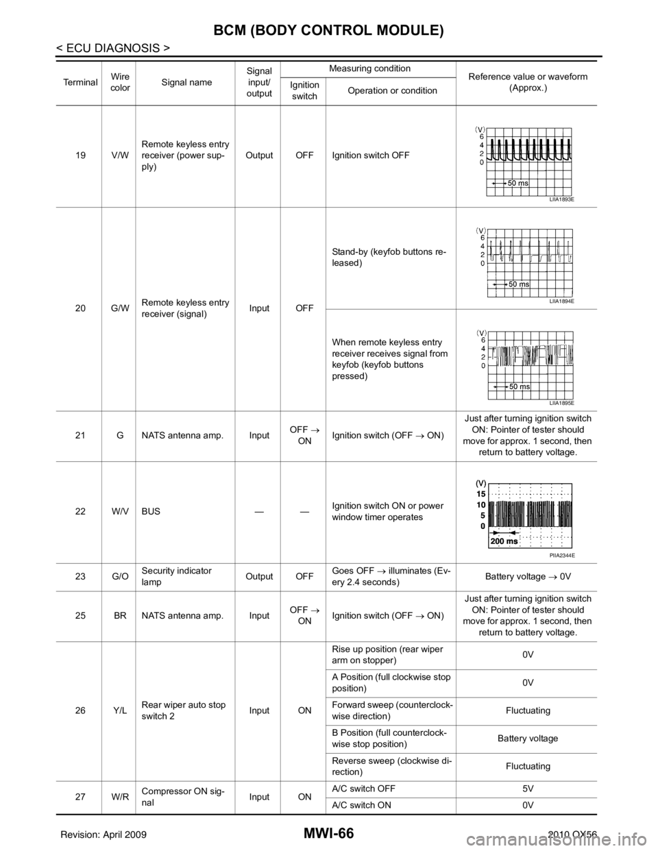
19 V/WRemote keyless entry
receiver (power sup-
ply) Output OFF Ignition switch OFF
20 G/W Remote keyless entry
receiver (signal) Input OFFStand-by (keyfob buttons re-
leased)
When remote keyless entry
receiver receives signal from
keyfob (keyfob buttons
pressed)
21 G NATS antenna amp. Input OFF
→
ON Ignition switch (OFF
→ ON)Just after turning ignition switch
ON: Pointer of tester should
move for approx. 1 second, then return to battery voltage.
22 W/V BUS — —Ignition switch ON or power
window timer operates
23 G/O Security indicator
lamp Output OFF
Goes OFF
→ illuminates (Ev-
ery 2.4 seconds) Battery voltage
→ 0V
25 BR NATS antenna amp. Input OFF
→
ON Ignition switch (OFF
→ ON)Just after turning ignition switch
ON: Pointer of tester should
move for approx. 1 second, then return to battery voltage.
26 Y/L Rear wiper auto stop
switch 2 Input ONRise up position (rear wiper
arm on stopper)
0V
A Position (full clockwise stop
position) 0V
Forward sweep (counterclock-
wise direction) Fluctuating
B Position (full counterclock-
wise stop position) Battery voltage
Reverse sweep (clockwise di-
rection) Fluctuating
27 W/R Compressor ON sig-
nal Input ONA/C switch OFF
5V
A/C switch ON 0V
Te r m i n a l
Wire
color Signal name Signal
input/
output Measuring condition
Reference value or waveform
(Approx.)
Ignition
switch Operation or condition
LIIA1893E
LIIA1894E
LIIA1895E
PIIA2344E
Revision: April 20092010 QX56
Page 3071 of 4210
PWC-86
< ECU DIAGNOSIS >
BCM (BODY CONTROL MODULE)
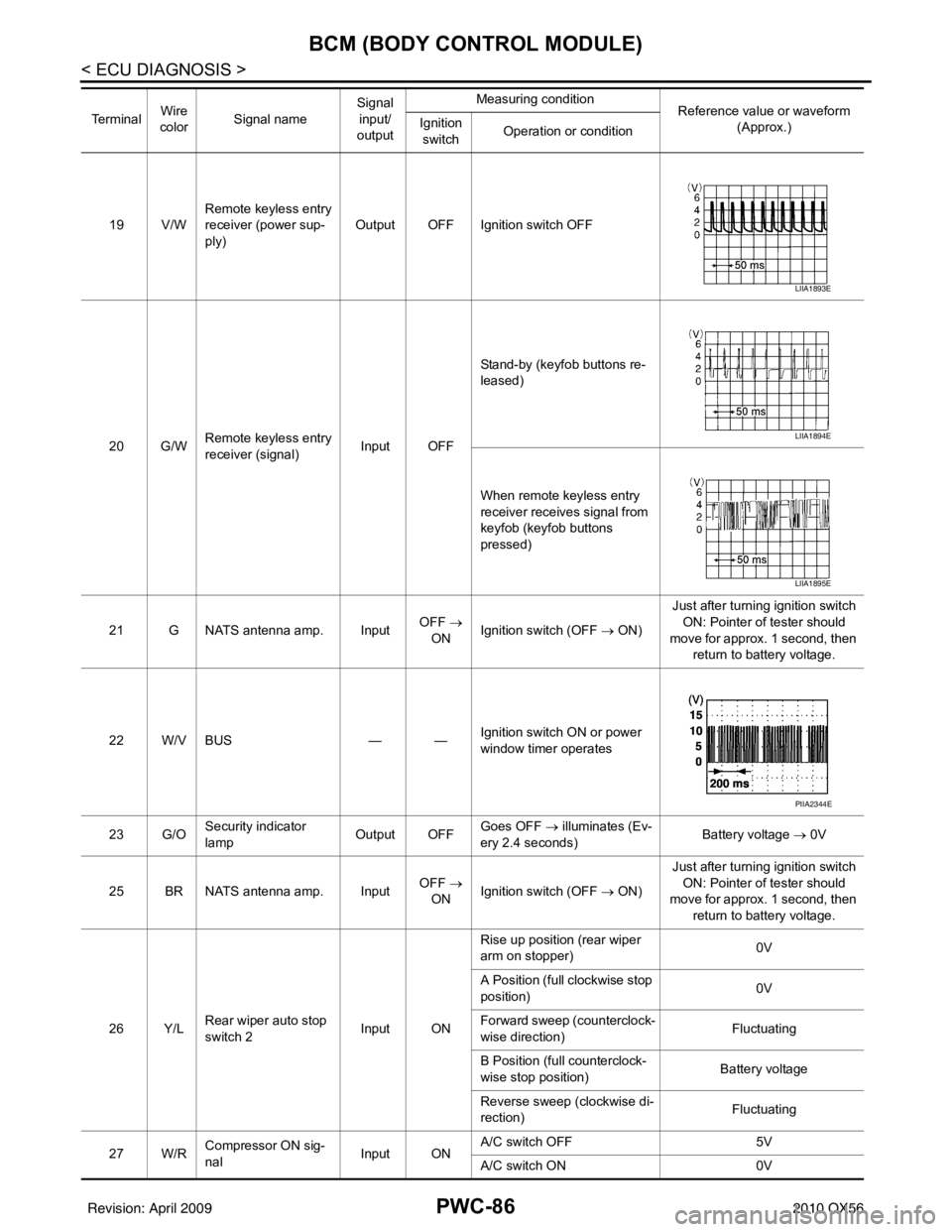
19 V/WRemote keyless entry
receiver (power sup-
ply) Output OFF Ignition switch OFF
20 G/W Remote keyless entry
receiver (signal) Input OFFStand-by (keyfob buttons re-
leased)
When remote keyless entry
receiver receives signal from
keyfob (keyfob buttons
pressed)
21 G NATS antenna amp. Input OFF
→
ON Ignition switch (OFF
→ ON)Just after turning ignition switch
ON: Pointer of tester should
move for approx. 1 second, then return to battery voltage.
22 W/V BUS — —Ignition switch ON or power
window timer operates
23 G/O Security indicator
lamp Output OFF
Goes OFF
→ illuminates (Ev-
ery 2.4 seconds) Battery voltage
→ 0V
25 BR NATS antenna amp. Input OFF
→
ON Ignition switch (OFF
→ ON)Just after turning ignition switch
ON: Pointer of tester should
move for approx. 1 second, then return to battery voltage.
26 Y/L Rear wiper auto stop
switch 2 Input ONRise up position (rear wiper
arm on stopper)
0V
A Position (full clockwise stop
position) 0V
Forward sweep (counterclock-
wise direction) Fluctuating
B Position (full counterclock-
wise stop position) Battery voltage
Reverse sweep (clockwise di-
rection) Fluctuating
27 W/R Compressor ON sig-
nal Input ONA/C switch OFF
5V
A/C switch ON 0V
Te r m i n a l
Wire
color Signal name Signal
input/
output Measuring condition
Reference value or waveform
(Approx.)
Ignition
switch Operation or condition
LIIA1893E
LIIA1894E
LIIA1895E
PIIA2344E
Revision: April 20092010 QX56
Page 3150 of 4210
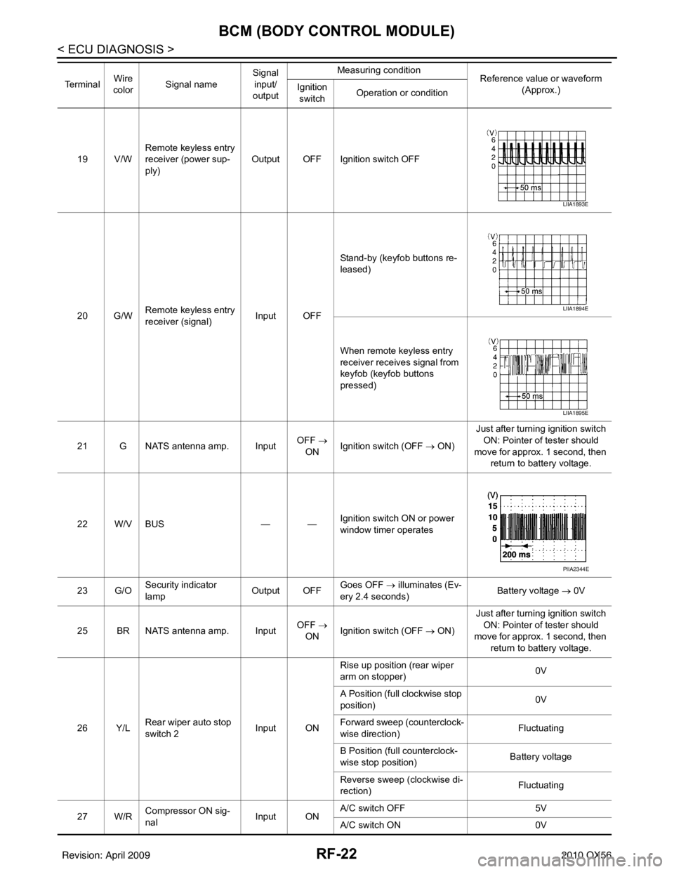
RF-22
< ECU DIAGNOSIS >
BCM (BODY CONTROL MODULE)
19 V/WRemote keyless entry
receiver (power sup-
ply) Output OFF Ignition switch OFF
20 G/W Remote keyless entry
receiver (signal) Input OFFStand-by (keyfob buttons re-
leased)
When remote keyless entry
receiver receives signal from
keyfob (keyfob buttons
pressed)
21 G NATS antenna amp. Input OFF
→
ON Ignition switch (OFF
→ ON)Just after turning ignition switch
ON: Pointer of tester should
move for approx. 1 second, then return to battery voltage.
22 W/V BUS — —Ignition switch ON or power
window timer operates
23 G/O Security indicator
lamp Output OFF
Goes OFF
→ illuminates (Ev-
ery 2.4 seconds) Battery voltage
→ 0V
25 BR NATS antenna amp. Input OFF
→
ON Ignition switch (OFF
→ ON)Just after turning ignition switch
ON: Pointer of tester should
move for approx. 1 second, then return to battery voltage.
26 Y/L Rear wiper auto stop
switch 2 Input ONRise up position (rear wiper
arm on stopper)
0V
A Position (full clockwise stop
position) 0V
Forward sweep (counterclock-
wise direction) Fluctuating
B Position (full counterclock-
wise stop position) Battery voltage
Reverse sweep (clockwise di-
rection) Fluctuating
27 W/R Compressor ON sig-
nal Input ONA/C switch OFF
5V
A/C switch ON 0V
Te r m i n a l
Wire
color Signal name Signal
input/
output Measuring condition
Reference value or waveform
(Approx.)
Ignition
switch Operation or condition
LIIA1893E
LIIA1894E
LIIA1895E
PIIA2344E
Revision: April 20092010 QX56
Page 3416 of 4210
![INFINITI QX56 2010 Factory Service Manual BCM (BODY CONTROL MODULE)SEC-65
< ECU DIAGNOSIS > [WITH INTELLIGENT KEY SYSTEM]
C
D
E
F
G H
I
J
L
M A
B
SEC
N
O P
19 V/W Remote keyless entry
receiver (power sup-
ply) Output OFF Ignition switch OFF
INFINITI QX56 2010 Factory Service Manual BCM (BODY CONTROL MODULE)SEC-65
< ECU DIAGNOSIS > [WITH INTELLIGENT KEY SYSTEM]
C
D
E
F
G H
I
J
L
M A
B
SEC
N
O P
19 V/W Remote keyless entry
receiver (power sup-
ply) Output OFF Ignition switch OFF](/manual-img/42/57032/w960_57032-3415.png)
BCM (BODY CONTROL MODULE)SEC-65
< ECU DIAGNOSIS > [WITH INTELLIGENT KEY SYSTEM]
C
D
E
F
G H
I
J
L
M A
B
SEC
N
O P
19 V/W Remote keyless entry
receiver (power sup-
ply) Output OFF Ignition switch OFF
20 G/W Remote keyless entry
receiver (signal) Input OFFStand-by (keyfob buttons re-
leased)
When remote keyless entry
receiver receives signal from
keyfob (keyfob buttons
pressed)
21 G NATS antenna amp. Input OFF
→
ON Ignition switch (OFF → ON) Just after turning ignition switch
ON: Pointer of tester should
move for approx. 1 second, then return to battery voltage.
22 W/V BUS — —Ignition switch ON or power
window timer operates
23 G/O Security indicator
lamp Output OFF
Goes OFF
→ illuminates (Ev-
ery 2.4 seconds) Battery voltage
→ 0V
25 BR NATS antenna amp. Input OFF
→
ON Ignition switch (OFF → ON) Just after turning ignition switch
ON: Pointer of tester should
move for approx. 1 second, then return to battery voltage.
26 Y/L Rear wiper auto stop
switch 2 Input ONRise up position (rear wiper
arm on stopper)
0V
A Position (full clockwise stop
position) 0V
Forward sweep (counterclock-
wise direction) Fluctuating
B Position (full counterclock-
wise stop position) Battery voltage
Reverse sweep (clockwise di-
rection) Fluctuating
27 W/R Compressor ON sig-
nal Input ONA/C switch OFF
5V
A/C switch ON 0V
Te r m i n a l
Wire
color Signal name Signal
input/
output Measuring condition
Reference value or waveform
(Approx.)
Ignition
switch Operation or condition
LIIA1893E
LIIA1894E
LIIA1895E
PIIA2344E
Revision: April 20092010 QX56