2010 INFINITI QX56 fuel cap
[x] Cancel search: fuel capPage 1735 of 4210
![INFINITI QX56 2010 Factory Service Manual EC-382
< COMPONENT DIAGNOSIS >[VK56DE]
P2A00, P2A03 A/F SENSOR 1
P2A00, P2A03 A/F SENSOR 1
Component DescriptionINFOID:0000000005149460
The air fuel ratio (A/F) sensor 1 is a planar one-cell limit cur INFINITI QX56 2010 Factory Service Manual EC-382
< COMPONENT DIAGNOSIS >[VK56DE]
P2A00, P2A03 A/F SENSOR 1
P2A00, P2A03 A/F SENSOR 1
Component DescriptionINFOID:0000000005149460
The air fuel ratio (A/F) sensor 1 is a planar one-cell limit cur](/manual-img/42/57032/w960_57032-1734.png)
EC-382
< COMPONENT DIAGNOSIS >[VK56DE]
P2A00, P2A03 A/F SENSOR 1
P2A00, P2A03 A/F SENSOR 1
Component DescriptionINFOID:0000000005149460
The air fuel ratio (A/F) sensor 1 is a planar one-cell limit current sen-
sor. The sensor element of the
A/F sensor 1 is composed an elec-
trode layer, which transports ions. It has a heater in the element.
The sensor is capable of precise measurement = 1, but also in the
lean and rich range. Together with its control electronics, the sensor
outputs a clear, continuous signal throughout a wide range.
The exhaust gas components diffuse through the diffusion layer at
the sensor cell. An electrode layer is applied voltage, and this current
relative oxygen density in lean. Also this current relative hydrocar-
bon density in rich.
Therefore, the A/F sensor 1 is able to indicate air fuel ratio by this
electrode layer of current. In addition, a heater is integrated in the
sensor to ensure the required operating temperature of about 800° C
(1,472° F).
On Board Diagn osis LogicINFOID:0000000005149461
To judge the malfunction, the A/F signal computed by ECM from the A/F sensor 1 signal is monitored not to be
shifted to LEAN side or RICH side.
DTC Confirmation ProcedureINFOID:0000000005149462
NOTE:
If DTC Confirmation Procedure has been previously conducted, always perform the following procedure
before conducting the next step.
1. Turn ignition switch OFF and wait at least 10 seconds.
2. Turn ignition switch ON.
3. Turn ignition switch OFF and wait at least 10 seconds.
TESTING CONDITION:
Before performing the following procedure, confirm that battery voltage is more than 11 V at idle.
WITH CONSULT-III
1. Start engine and warm it up to normal operating temperature.
2. Turn ignition switch OFF and wait at least 10 seconds.
3. Turn ignition switch ON and select “SELF-LEARNING CONT” in “WORK SUPPORT” mode with CON-
SULT-III.
4. Clear the self-learning coef ficient by touching “CLEAR”.
PBIB3353E
PBIB3354E
DTC No. Trouble diagnosis name DTC detecting conditionPossible Cause
P2A00
2A00
(Bank 1) Air fuel ratio (A/F) sensor 1
circuit range/performance • The output voltage computed by ECM from the
A/F sensor 1 signal is shifted to the lean side for
a specified period.
• The A/F signal computed by ECM from the A/F
sensor 1 signal is shifted to the rich side for a
specified period. • A/F sensor 1
• A/F sensor 1 heater
• Fuel pressure
• Fuel injector
• Intake air leaks
P2A03
2A03
(Bank 2)
Revision: April 20092010 QX56
Page 1833 of 4210
![INFINITI QX56 2010 Factory Service Manual EC-480
< SYMPTOM DIAGNOSIS >[VK56DE]
ENGINE CONTROL SYSTEM SYMPTOMS
1 - 6: The numbers refer to the order of inspection.Exhaust Exhaust manifold/Tube/Muffler/
Gasket 55555 55 5EM-30
,
EX-
5Three way INFINITI QX56 2010 Factory Service Manual EC-480
< SYMPTOM DIAGNOSIS >[VK56DE]
ENGINE CONTROL SYSTEM SYMPTOMS
1 - 6: The numbers refer to the order of inspection.Exhaust Exhaust manifold/Tube/Muffler/
Gasket 55555 55 5EM-30
,
EX-
5Three way](/manual-img/42/57032/w960_57032-1832.png)
EC-480
< SYMPTOM DIAGNOSIS >[VK56DE]
ENGINE CONTROL SYSTEM SYMPTOMS
1 - 6: The numbers refer to the order of inspection.Exhaust Exhaust manifold/Tube/Muffler/
Gasket 55555 55 5EM-30
,
EX-
5Three way catalyst
Lubrica-
tion Oil pan/Oil strainer/Oil pump/Oil
filter/Oil gallery/Oil cooler
55555 55 5EM-33
,
LU-
14 , LU-11 ,
LU-12
Oil level (Low)/Filthy oil LU-8, "In-
spection"
Cooling Radiator/Hose/Radiator filler cap
55555 55 45 CO-15
Thermostat
5CO-22
Water pump CO-20
Water galleryCO-6
Cooling fan5CO-18,
CO-
19
Coolant level (Low)/Contaminat-
ed coolant 5
CO-10
IVIS (INFINITI Vehicle Immobilizer System —
NATS) 11
SEC-9
SYMPTOM
Reference
page
HARD/NO START/RESTART (EXCP. HA)
ENGINE STALL
HESITATION/SURGING/FLAT SPOT
SPARK KNOCK/DETONATION
LACK OF POWER/POOR ACCELERATION
HIGH IDLE/LOW IDLE
ROUGH IDLE/HUNTING
IDLING VIBRATION
SLOW/NO RETURN TO IDLE
OVERHEATS/WATER TEMPERATURE HIGH
EXCESSIVE FUEL CONSUMPTION
EXCESSIVE OIL CONSUMPTION
BATTERY DEAD (UNDER CHARGE)
Warranty symptom code AA AB AC AD AE AF AG AH AJ AK AL AM HA
Revision: April 20092010 QX56
Page 1839 of 4210
![INFINITI QX56 2010 Factory Service Manual EC-486
< PREPARATION >[VK56DE]
PREPARATION
PREPARATION
PREPARATION
Special Service ToolINFOID:0000000005149505
The actual shapes of Kent-Moore tool
s may differ from those of special service tools ill INFINITI QX56 2010 Factory Service Manual EC-486
< PREPARATION >[VK56DE]
PREPARATION
PREPARATION
PREPARATION
Special Service ToolINFOID:0000000005149505
The actual shapes of Kent-Moore tool
s may differ from those of special service tools ill](/manual-img/42/57032/w960_57032-1838.png)
EC-486
< PREPARATION >[VK56DE]
PREPARATION
PREPARATION
PREPARATION
Special Service ToolINFOID:0000000005149505
The actual shapes of Kent-Moore tool
s may differ from those of special service tools illustrated here.
Tool number
(Kent-Moore No.)
Tool nameDescription
EG17650301
(J-33984-A)
Radiator cap tester
adapter Adapting radiator cap tester to radiator cap and ra-
diator filler neck
a: 28 (1.10) dia.
b: 31.4 (1.236) dia.
c: 41.3 (1.626) dia.
Unit: mm (in)
KV10117100
(J-36471-A)
Heated oxygen sensor
wrench Loosening or tightening heated oxygen sensors
with 22 mm (0.87 in) hexagon nut
KV10114400
(J-38365)
Heated oxygen sensor
wrench Loosening or tightening heated oxygen sensors
a: 22 mm (0.87 in)
(J-44626)
Air fuel ratio (A/F) sen-
sor wrench Loosening or tightening air fuel ratio (A/F) sensor 1
(J-44321)
Fuel pressure gauge
kit Checking fuel pressure
(J-44321-6)
Fuel pressure adapter Connecting fuel pressure gauge to quick connec-
tor type fuel lines.
S-NT564
S-NT379
S-NT636
LEM054
LEC642
LBIA0376E
Revision: April 20092010 QX56
Page 1840 of 4210
![INFINITI QX56 2010 Factory Service Manual PREPARATIONEC-487
< PREPARATION > [VK56DE]
C
D
E
F
G H
I
J
K L
M A
EC
NP
O
Commercial Service ToolINFOID:0000000005149506
(J-45488)
Quick connector re-
lease
Remove fuel tube quick connectors in engin INFINITI QX56 2010 Factory Service Manual PREPARATIONEC-487
< PREPARATION > [VK56DE]
C
D
E
F
G H
I
J
K L
M A
EC
NP
O
Commercial Service ToolINFOID:0000000005149506
(J-45488)
Quick connector re-
lease
Remove fuel tube quick connectors in engin](/manual-img/42/57032/w960_57032-1839.png)
PREPARATIONEC-487
< PREPARATION > [VK56DE]
C
D
E
F
G H
I
J
K L
M A
EC
NP
O
Commercial Service ToolINFOID:0000000005149506
(J-45488)
Quick connector re-
lease
Remove fuel tube quick connectors in engine
room.
(J-23688)
Engine coolant refrac-
tometer Checking concentration of ethylene glycol in en-
gine coolant
Tool number
(Kent-Moore No.)
Tool name
Description
PBIC0198E
WBIA0539E
Tool name
(Kent-Moore No.)
Description
Leak detector
i.e.: (J-41416) Locating the EVAP leak
EVAP service port
adapter
i.e.: (J-41413-OBD) Applying positive pressure through EVAP service
port
Fuel filler cap adapter
i.e.: (MLR-8382) Checking fuel tank vacuum relief valve opening
pressure
Socket wrench Removing and installing engine coolant tempera-
ture sensor
S-NT703
S-NT704
S-NT815
S-NT705
Revision: April 20092010 QX56
Page 1855 of 4210

EM-4
< PRECAUTION >
PRECAUTIONS
5. When the repair work is completed, return the ignition switch to the ″LOCK ″ position before connecting
the battery cables. (At this time, the steering lock mechanism will engage.)
6. Perform a self-diagnosis check of a ll control units using CONSULT-III.
Precaution for Drain Engine CoolantINFOID:0000000005148963
Drain engine coolant when engine is cooled.
Precaution for Disconnecting Fuel PipingINFOID:0000000005148964
• Before starting work, make sure no fire or spark producing items are in the work area.
• Release fuel pressure before disconnecting and disassembly.
• After disconnecting pipes, plug openings to stop fuel leakage.
Precaution for Removal and DisassemblyINFOID:0000000005148965
• When instructed to use special service tools, use the s pecified tools. Always be careful to work safely, avoid
forceful or uninstructed operations.
• Exercise maximum care to avoid damage to mating or sliding surfaces.
• Cover openings of engine system with tape or the equivalent, if necessary, to seal out foreign materials.
• Mark and arrange disassembly parts in an organi zed way for easy troubleshooting and assembly.
• When loosening nuts and bolts, as a basic rule, start with the one furthest outside, then the one diagonally opposite, and so on. If the order of loosening is specified, do exactly as specified. Power tools may be used
where noted in the step.
Precaution for Inspection, Repair and ReplacementINFOID:0000000005148966
Before repairing or replacing, thoroughly inspect parts. Inspect new replacement parts in the same way, and
replace if necessary.
Precaution for Assembly and InstallationINFOID:0000000005148967
• Use torque wrench to tighten bolts or nuts to specification.
• When tightening nuts and bolts, as a basic rule, equally tighten in several different steps starting with theones in center, then ones on inside and outside diagonally in this order. If the order of tightening is specified,
do exactly as specified.
• Replace with new gasket, packing, oil seal or O-ring.
• Thoroughly wash, clean, and air-blow each part. Carefully check engine oil or engine coolant passages for any restriction and blockage.
• Avoid damaging sliding or mating surfaces. Completely remove foreign materials such as cloth lint or dust. Before assembly, oil sliding surfaces well.
• Release air within route when refilling after draining engine coolant.
• Before starting engine, apply fuel pressure to fuel lines with turning ignition switch ON (with engine stopped). Then make sure that there are no leaks at fuel line connections.
• After repairing, start engine and increase engine s peed to check engine coolant, fuel, oil, and exhaust sys-
tems for leakage.
Parts Requiring Angular TighteningINFOID:0000000005148968
• For final tightening of the following engine parts use Tool:
- Cylinder head bolts
- Main bearing cap bolts
- Connecting rod cap bolts
- Crankshaft pulley bolt (No angle wrench is required as the bolt flange is provided with notches for angle tightening)
• Do not use a torque value for final tightening.
• The torque value for these parts are for a preliminary step.
• Ensure thread and seat surfaces are clean and lightly coated with engine oil. Tool number : KV10112100 (BT-8653-A)
Revision: April 20092010 QX56
Page 1857 of 4210

EM-6
< PREPARATION >
PREPARATION
PREPARATION
PREPARATION
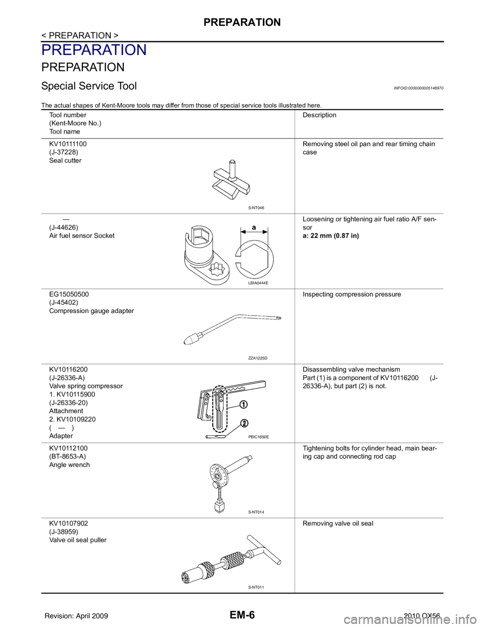
Special Service ToolINFOID:0000000005148970
The actual shapes of Kent-Moore tools may differ from those of special service tools illustrated here.
Tool number
(Kent-Moore No.)
Tool name Description
K V 1 0 1111 0 0
(J-37228)
Seal cutter Removing steel oil pan and rear timing chain
case
—
(J-44626)
Air fuel sensor Socket Loosening or tightening air fuel ratio A/F sen-
sor
a: 22 mm (0.87 in)
EG15050500
(J-45402)
Compression gauge adapter Inspecting compression pressure
KV10116200
(J-26336-A)
Valve spring compressor
1. KV10115900
(J-26336-20)
Attachment
2. KV10109220
(—)
Adapter Disassembling valve mechanism
Part (1) is a component of KV10116200 (J-
26336-A), but part (2) is not.
KV10112100
(BT-8653-A)
Angle wrench Tightening bolts for cylinder head, main bear-
ing cap and connecting rod cap
KV10107902
(J-38959)
Valve oil seal puller Removing valve oil seal
S-NT046
LBIA0444E
ZZA1225D
PBIC1650E
S-NT014
S-NT011
Revision: April 20092010 QX56
Page 1878 of 4210

INTAKE MANIFOLDEM-27
< ON-VEHICLE REPAIR >
C
DE
F
G H
I
J
K L
M A
EM
NP
O
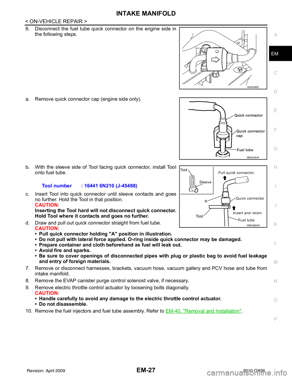
6. Disconnect the fuel tube quick connector on the engine side in
the following steps.
a. Remove quick connector cap (engine side only).
b. With the sleeve side of Tool facing quick connector, install Tool onto fuel tube.
c. Insert Tool into quick connector until sleeve contacts and goes no further. Hold the Tool in that position.
CAUTION:
Inserting the Tool hard will not disconnect quick connector.
Hold Tool where it cont acts and goes no further.
d. Draw and pull out quick connector straight from fuel tube. CAUTION:
• Pull quick connector holding "A" position in illustration.
• Do not pull with lateral force applied. O-ring inside quick connector may be damaged.
• Prepare container and cloth be forehand as fuel will leak out.
• Avoid fire and sparks.
• Be sure to cover openings of disconnected pipes with plug or plastic bag to avoid fuel leakage and entry of foreign materials.
7. Remove or disconnect harnesses, brackets, vac uum hose, vacuum gallery and PCV hose and tube from
intake manifold.
8. Remove the EVAP canister purge control solenoid valve, if necessary.
9. Remove electric throttle control actuator by loosening bolts diagonally. CAUTION:
• Handle carefully to avoid any damage to the electric throttle control actuator.
• Do not disassemble.
10. Remove the fuel injectors and fuel tube assembly. Refer to EM-40, "
Removal and Installation".
LBIA0395E
SBIA0354E
Tool number : 16441 6N210 (J-45488)
WBIA0604E
Revision: April 20092010 QX56
Page 1879 of 4210

EM-28
< ON-VEHICLE REPAIR >
INTAKE MANIFOLD
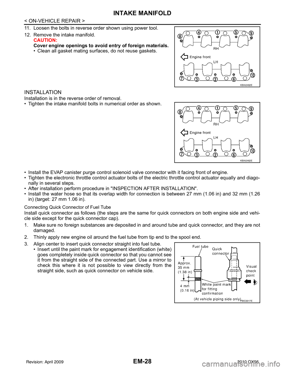
11. Loosen the bolts in reverse order shown using power tool.
12. Remove the intake manifold.CAUTION:
Cover engine openings to avoid entry of foreign materials.
• Clean all gasket mating surfaces, do not reuse gaskets.
INSTALLATION
Installation is in the reverse order of removal.
• Tighten the intake manifold bolts in numerical order as shown.
• Install the EVAP canister purge control sol enoid valve connector with it facing front of engine.
• Tighten the electronic throttle control actuator bolts of the electric throttle control actuator equally and diago-
nally in several steps.
• After installation perform procedure in "INSPECTION AFTER INSTALLATION".
• Install the water hose so that its overlap width for connection is between 27 mm (1.06 in) and 32 mm (1.26 in) (target: 27 mm 1.06 in).
Connecting Quick Connector of Fuel Tube
Install quick connector as follows (the steps are t he same for quick connectors on both engine side and vehi-
cle side except for the quick connector cap).
1. Make sure no foreign substances are deposited in and around tube and quick connector, and they are not
damaged.
2. Thinly apply new engine oil around the fuel tube from tip end to the spool end.
3. Align center to insert quick connector straight into fuel tube. • Insert until the paint mark for engagement identification (white)goes completely inside quick connector so that you cannot see
it from the straight side of the connected part. Use a mirror to
check this where it is not possible to view directly from the
straight side, such as quick connector on vehicle side.
KBIA2462E
KBIA2462E
PBIC0017E
Revision: April 20092010 QX56