2010 INFINITI QX56 transmission fluid
[x] Cancel search: transmission fluidPage 2716 of 4210
MA-12
< ON-VEHICLE MAINTENANCE >
PERIODIC MAINTENANCE
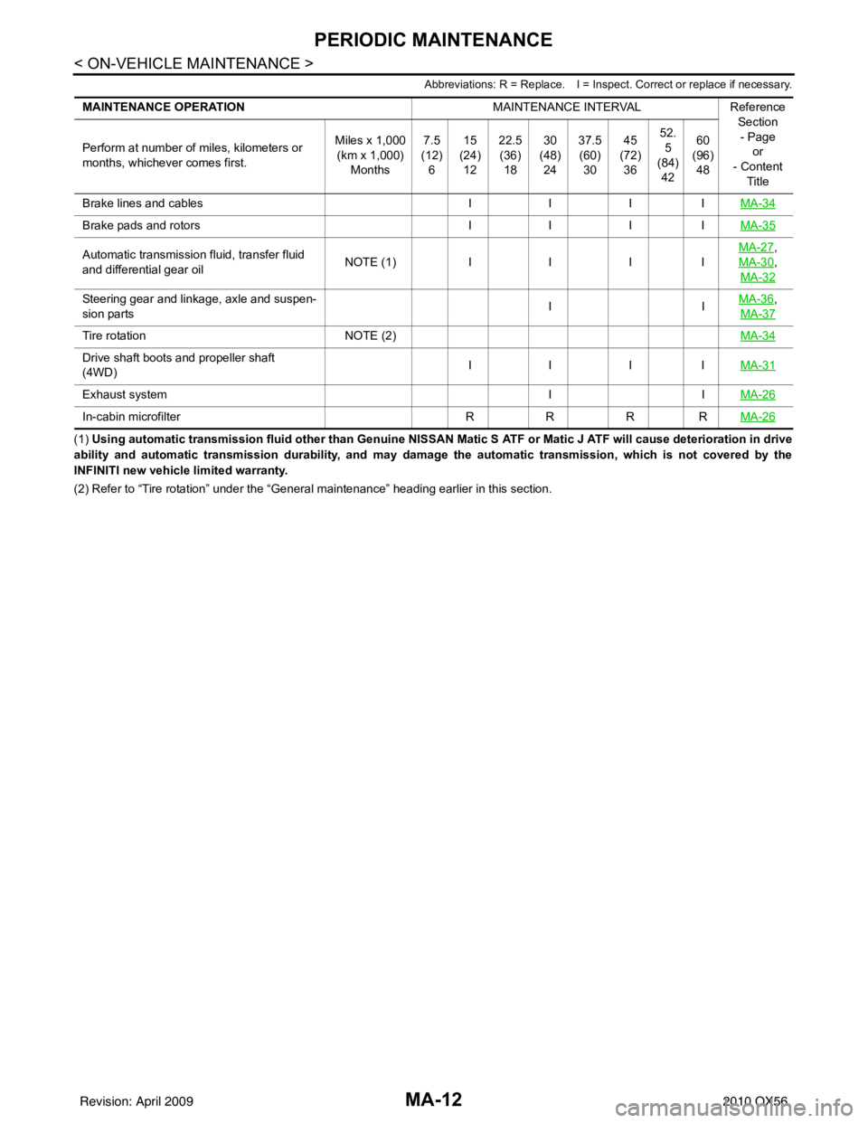
Abbreviations: R = Replace. I = Inspect. Correct or replace if necessary.
(1) Using automatic transmission fluid other than Genuine NISSAN Matic S ATF or Matic J ATF will cause deterioration in drive
ability and automatic transmission durability, and may damage the automatic transmission, which is not covered by the
INFINITI new vehicle limited warranty.
(2) Refer to “Tire rotation” unde r the “General maintenance” heading earlier in this section.
MAINTENANCE OPERATION
MAINTENANCE INTERVALReference
Section
- Page or
- Content
Title
Perform at number of miles, kilometers or
months, whichever comes first.
Miles x 1,000
(km x 1,000)
Months 7.5
(12)
6 15
(24)
12 22.5
(36)
18 30
(48)
24 37.5
(60)
30 45
(72)
36 52.
5
(84) 42 60
(96)
48
Brake lines and cables IIIIMA-34
Brake pads and rotors IIIIMA-35
Automatic transmission fluid, transfer fluid
and differential gear oil N
O TE (1)IIII MA-27,
MA-30
,
MA-32
Steering gear and linkage, axle and suspen-
sion parts IIMA-36,
MA-37
Tire rotation NOTE (2) MA-34
Drive shaft boots and propeller shaft
(4WD)IIII
MA-31
Exhaust system IIMA-26
In-cabin microfilter RRRRMA-26
Revision: April 20092010 QX56
Page 2717 of 4210
RECOMMENDED FLUIDS AND LUBRICANTSMA-13
< ON-VEHICLE MAINTENANCE >
C
DE
F
G H
I
J
K L
M B
MA
N
O A
RECOMMENDED FLUIDS AND LUBRICANTS
Fluids and LubricantsINFOID:0000000005145938
*1: For further details, refer to
MA-14, "Engine Oil Recommendation".
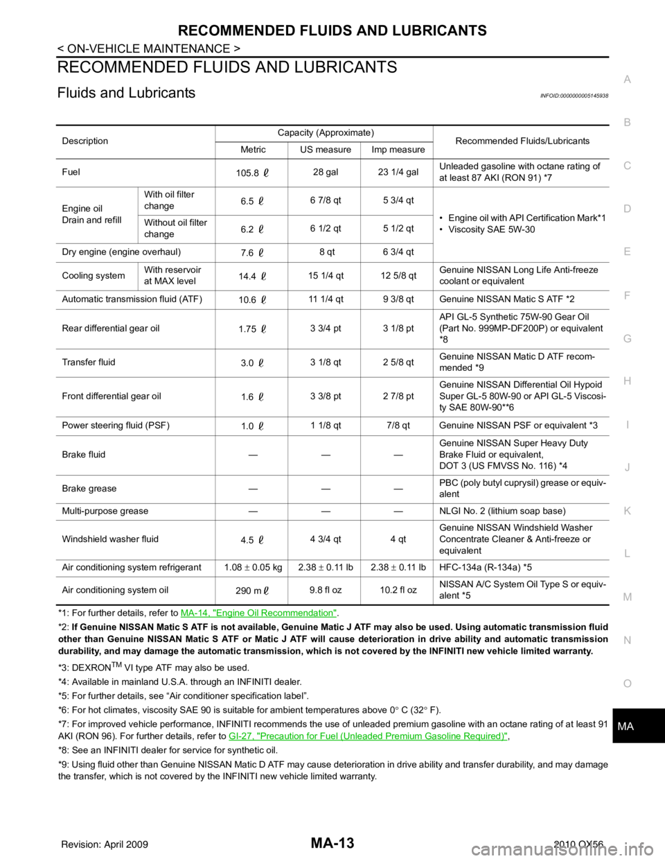
*2: If Genuine NISSAN Matic S ATF is not ava ilable, Genuine Matic J ATF may also be used. Using automatic transmission fluid
other than Genuine NISSAN Matic S ATF or Matic J ATF will cause deterioration in drive ability and automatic transmission
durability, and may damage the automatic transmission, which is not covered by the INFINITI new vehicle limited warranty.
*3: DEXRON
TM VI type ATF may also be used.
*4: Available in mainland U.S.A. through an INFINITI dealer.
*5: For further details, see “Air conditioner specification label”.
*6: For hot climates, viscosity SAE 90 is suitable for ambient temperatures above 0° C (32° F).
*7: For improved vehicle performance, INFINITI recommends the use of unleaded premium gasoline with an octane rating of at leas t 91
AKI (RON 96). For furt her details, refer to GI-27, "
Precaution for Fuel (Unleaded Premium Gasoline Required)",
*8: See an INFINITI dealer for service for synthetic oil.
*9: Using fluid other than Genuin e NISSAN Matic D ATF may cause deterioration in drive ability and transfer durability, and may damage
the transfer, which is not covered by the INFINITI new vehicle limited warranty. Description
Capacity (Approximate)
Recommended Fluids/Lubricants
Metric US measure Imp measure
Fuel 105.8 28 gal 23 1/4 gal Unleaded gasoline with octane rating of
at least 87 AKI (RON 91) *7
Engine oil
Drain and refill With oil filter
change
6.5
6 7/8 qt 5 3/4 qt
• Engine oil with API Certification Mark*1
• Viscosity SAE 5W-30
Without oil filter
change
6.2
6 1/2 qt 5 1/2 qt
Dry engine (engine overhaul) 7.6 8 qt
6 3/4 qt
Cooling system With reservoir
at MAX level
14.4
15 1/4 qt 12 5/8 qt Genuine NISSAN Long
Life Anti-freeze
coolant or equivalent
Automatic transmission fluid (ATF) 10.6 11 1/4 qt 9 3/8 qt Genuine NISSAN Matic S ATF *2
Rear differential gear oil 1.75 3 3/4 pt 3 1/8 pt API GL-5 Synthetic 75W-90 Gear Oil
(Part No. 999MP-DF200P) or equivalent
*8
Transfer fluid 3.0 3 1/8 qt 2 5/8 qt Genuine NISSAN Matic D ATF recom-
mended *9
Front differential gear oil 1.6 3 3/8 pt 2 7/8 pt Genuine NISSAN Differ
ential Oil Hypoid
Super GL-5 80W-90 or API GL-5 Viscosi-
ty SAE 80W-90**6
Power steering fluid (PSF) 1.0 1 1/8 qt 7/8 qt Genuine NISSAN PSF or equivalent *3
Brake fluid ———Genuine NISSAN S
uper Heavy Duty
Brake Fluid or equivalent,
DOT 3 (US FMVSS No. 116) *4
Brake grease ———PBC (poly butyl cuprysil) grease or equiv-
alent
Multi-purpose grease ——— NLGI No. 2 (lithium soap base)
Windshield washer fluid 4.5 4 3/4 qt
4 qtGenuine NISSAN Wind
shield Washer
Concentrate Cleaner & Anti-freeze or
equivalent
Air conditioning system refrigerant 1.08 ± 0.05 kg 2.38 ± 0.11 lb 2.38 ± 0.11 lb HFC-134a (R-134a) *5
Air conditioning system oil 290 m9.8 fl oz 10.2 fl oz NISSAN A/C System Oil Type S or equiv-
alent *5
Revision: April 20092010 QX56
Page 2731 of 4210
CHASSIS AND BODY MAINTENANCEMA-27
< ON-VEHICLE MAINTENANCE >
C
DE
F
G H
I
J
K L
M B
MA
N
O A
• If anything is found, repair or replace damaged parts.
A/T FLUID
A/T FLUID : Checking
the A/T Fluid (ATF)INFOID:0000000005403151
CAUTION:
If using the vehicle for towing, the A/T fluid must be replaced as specified. Refer to MA-9, "
Introduc-
tion of Periodic Maintenance".
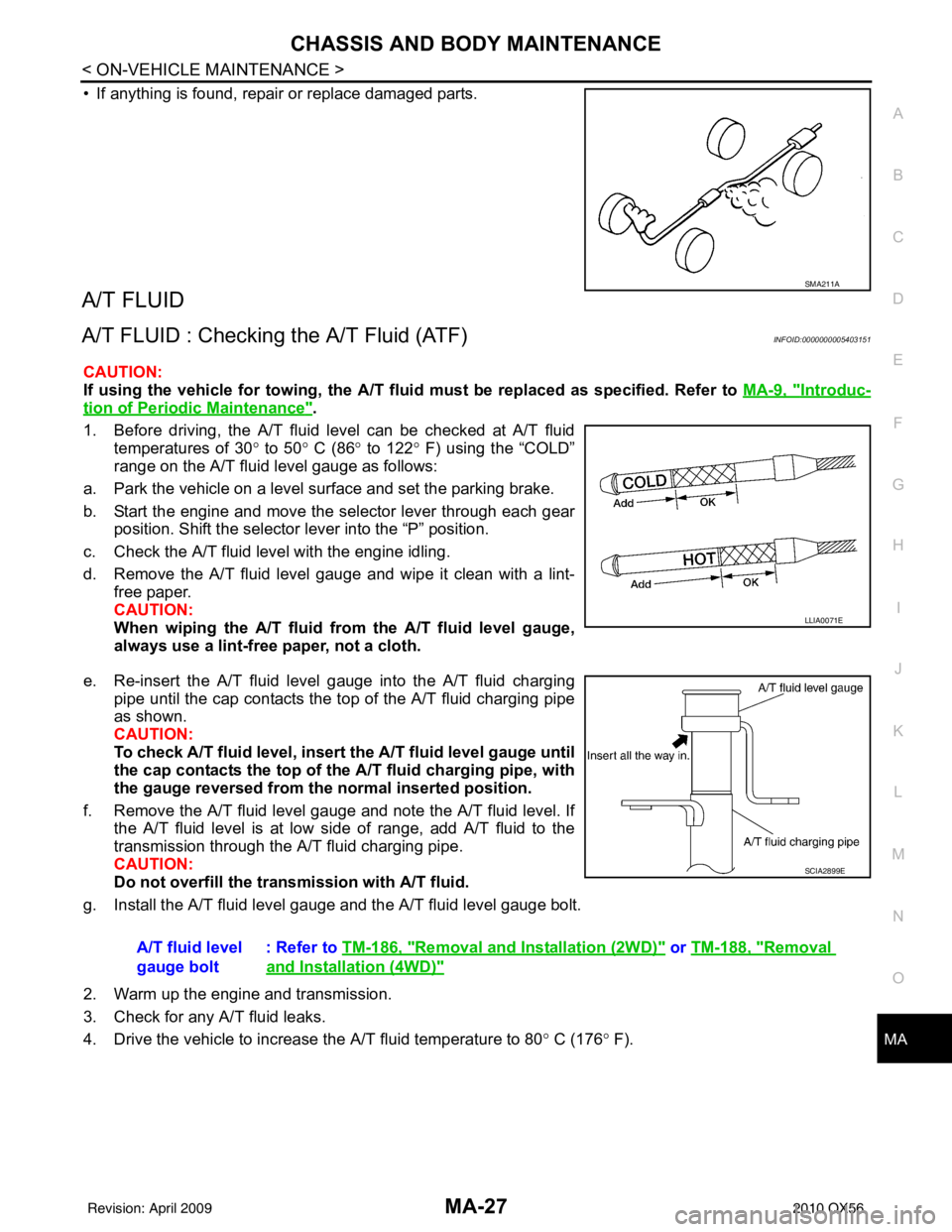
1. Before driving, the A/T fluid level can be checked at A/T fluid temperatures of 30 ° to 50 ° C (86 ° to 122° F) using the “COLD”
range on the A/T fluid level gauge as follows:
a. Park the vehicle on a level surface and set the parking brake.
b. Start the engine and move the selector lever through each gear position. Shift the selector lever into the “P” position.
c. Check the A/T fluid level with the engine idling.
d. Remove the A/T fluid level gauge and wipe it clean with a lint- free paper.
CAUTION:
When wiping the A/T fluid from the A/T fluid level gauge,
always use a lint-free paper, not a cloth.
e. Re-insert the A/T fluid level gauge into the A/T fluid charging pipe until the cap contacts the top of the A/T fluid charging pipe
as shown.
CAUTION:
To check A/T fluid level, insert th e A/T fluid level gauge until
the cap contacts the top of the A/T fluid charging pipe, with
the gauge reversed from the normal inserted position.
f. Remove the A/T fluid level gauge and note the A/T fluid level. If the A/T fluid level is at low side of range, add A/T fluid to the
transmission through the A/T fluid charging pipe.
CAUTION:
Do not overfill the tran smission with A/T fluid.
g. Install the A/T fluid level gauge and the A/T fluid level gauge bolt.
2. Warm up the engine and transmission.
3. Check for any A/T fluid leaks.
4. Drive the vehicle to increase the A/T fluid temperature to 80 ° C (176 ° F).
SMA211A
LLIA0071E
A/T fluid level
gauge bolt : Refer to
TM-186, "Removal and Installation (2WD)" or TM-188, "Removal
and Installation (4WD)"
SCIA2899E
Revision: April 20092010 QX56
Page 2732 of 4210
MA-28
< ON-VEHICLE MAINTENANCE >
CHASSIS AND BODY MAINTENANCE
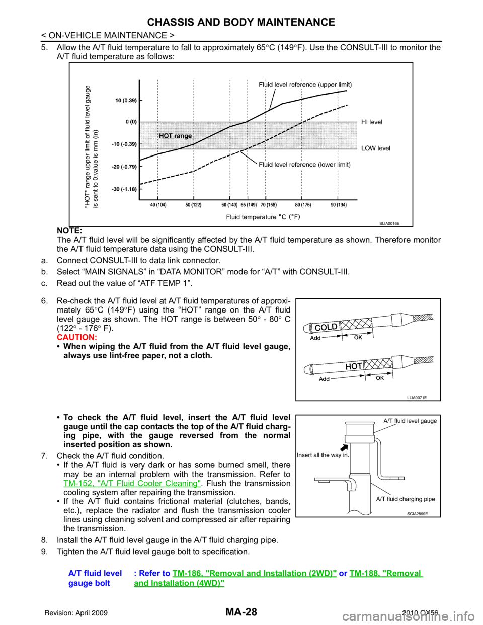
5. Allow the A/T fluid temperature to fall to approximately 65°C (149°F). Use the CONSULT-III to monitor the
A/T fluid temperature as follows:
NOTE:
The A/T fluid level will be significantly affected by t he A/T fluid temperature as shown. Therefore monitor
the A/T fluid temperature data using the CONSULT-III.
a. Connect CONSULT-III to data link connector.
b. Select “MAIN SIGNALS” in “DATA MONI TOR” mode for “A/T” with CONSULT-III.
c. Read out the value of “ATF TEMP 1”.
6. Re-check the A/T fluid level at A/T fluid temperatures of approxi- mately 65 °C (149° F) using the “HOT” range on the A/T fluid
level gauge as shown. The HOT range is between 50 ° - 80 ° C
(122° - 176 ° F).
CAUTION:
• When wiping the A/T fluid from the A/T fluid level gauge,
always use lint-free paper, not a cloth.
• To check the A/T fluid level , insert the A/T fluid level
gauge until the cap contacts the top of the A/T fluid charg-
ing pipe, with the gauge reversed from the normal
inserted position as shown.
7. Check the A/T fluid condition. • If the A/T fluid is very dark or has some burned smell, there
may be an internal problem with the transmission. Refer to
TM-152, "
A/T Fluid Cooler Cleaning". Flush the transmission
cooling system after repairing the transmission.
• If the A/T fluid contains frictional material (clutches, bands, etc.), replace the radiator and flush the transmission cooler
lines using cleaning solvent and compressed air after repairing
the transmission.
8. Install the A/T fluid level gauge in the A/T fluid charging pipe.
9. Tighten the A/T fluid level gauge bolt to specification.
SLIA0016E
LLIA0071E
A/T fluid level
gauge bolt : Refer to
TM-186, "Removal and Installation (2WD)" or TM-188, "Removal
and Installation (4WD)"
SCIA2899E
Revision: April 20092010 QX56
Page 2733 of 4210
CHASSIS AND BODY MAINTENANCEMA-29
< ON-VEHICLE MAINTENANCE >
C
DE
F
G H
I
J
K L
M B
MA
N
O A
A/T FLUID : Changing the A/T Fluid (ATF)INFOID:0000000005403152
CAUTION:
If using the vehicle for towing, the A/T fluid must be replaced as specified. Refer to
MA-9, "
Introduc-
tion of Periodic Maintenance".
1. Drive the vehicle to warm up the A/T fluid to approximately 80 ° C (176 ° F).
2. Stop the engine.
3. Remove the A/T fluid level gauge.
4. Drain the A/T fluid from the drain plug hole, then install the drain plug with a new gasket. Refill the transmission with new A/T
fluid. Always refill with the same volume as the drained A/T fluid.
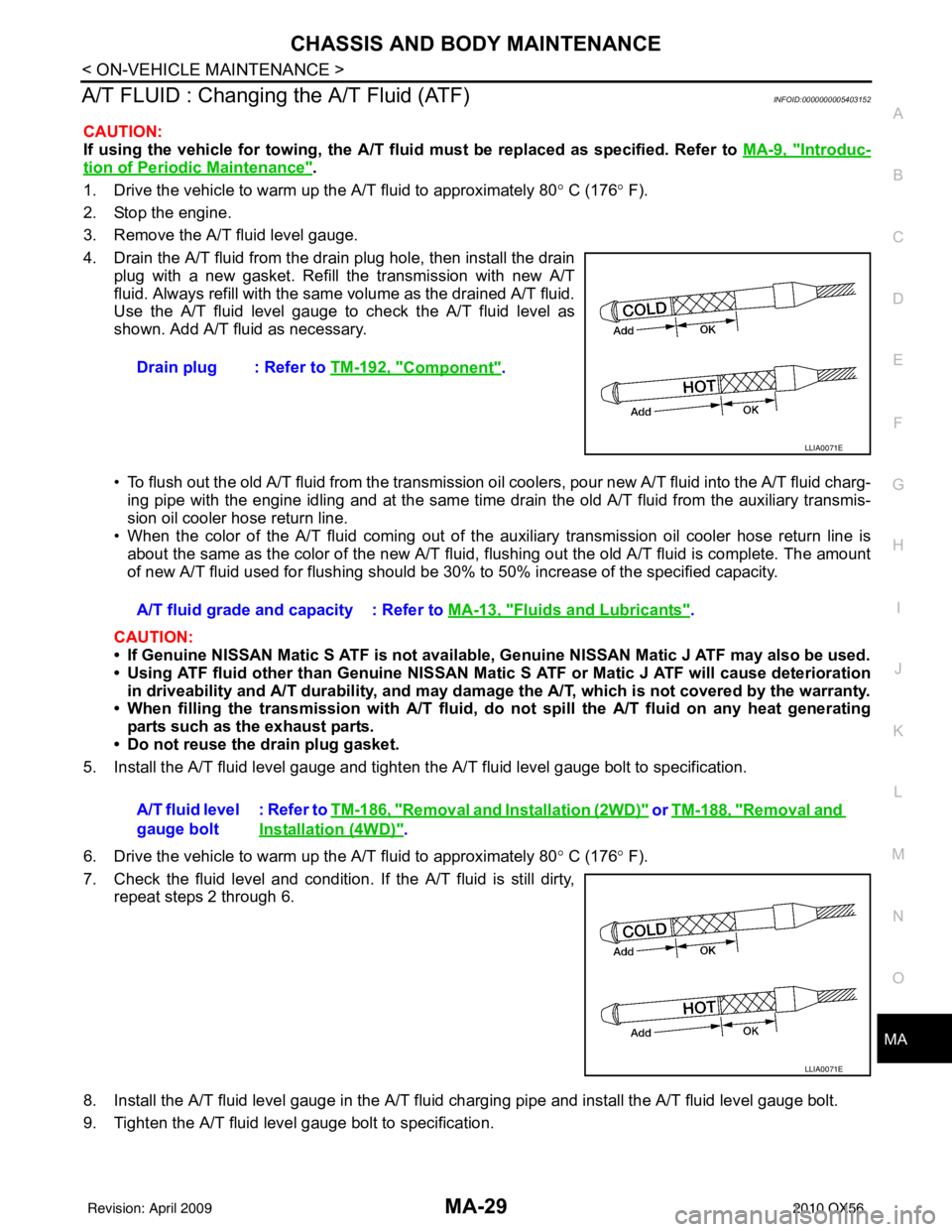
Use the A/T fluid level gauge to check the A/T fluid level as
shown. Add A/T fluid as necessary.
• To flush out the old A/T fluid from the transmission o il coolers, pour new A/T fluid into the A/T fluid charg-
ing pipe with the engine idling and at the same time drain the old A/T fluid from the auxiliary transmis-
sion oil cooler hose return line.
• When the color of the A/T fluid coming out of the aux iliary transmission oil cooler hose return line is
about the same as the color of the new A/T fluid, flushing out the old A/T fluid is complete. The amount
of new A/T fluid used for flushing should be 30% to 50% increase of the specified capacity.
CAUTION:
• If Genuine NISSAN Matic S ATF is not available, Genuine NISSAN Matic J ATF may also be used.
• Using ATF fluid other than Genuine NISSAN Matic S ATF or Matic J ATF will cause deterioration
in driveability and A/T durability, and may damage the A/T, which is not covered by the warranty.
• When filling the transmission with A/T fluid, do not spill the A/T fluid on any heat generating
parts such as the exhaust parts.
• Do not reuse the drain plug gasket.
5. Install the A/T fluid level gauge and tighten t he A/T fluid level gauge bolt to specification.
6. Drive the vehicle to warm up the A/T fluid to approximately 80 ° C (176 ° F).
7. Check the fluid level and condition. If the A/T fluid is still dirty, repeat steps 2 through 6.
8. Install the A/T fluid level gauge in the A/T fluid charging pipe and install the A/T fluid level gauge bolt.
9. Tighten the A/T fluid level gauge bolt to specification. Drain plug : Refer to
TM-192, "
Component".
LLIA0071E
A/T fluid grade and capacity : Refer to MA-13, "Fluids and Lubricants".
A/T fluid level
gauge bolt : Refer to
TM-186, "
Removal and Installation (2WD)" or TM-188, "Removal and
Installation (4WD)".
LLIA0071E
Revision: April 20092010 QX56
Page 3697 of 4210

TM-2
On Board Diagnosis Logic ......................................50
Possible Cause .......................................................50
DTC Confirmation Procedure .................................50
Diagnosis Procedure ..............................................51
P0725 ENGINE SPEED .....................................53
Description ........................................................... ...53
CONSULT-III Reference Value in Data Monitor
Mode .................................................................... ...
53
On Board Diagnosis Logic ......................................53
Possible Cause .......................................................53
DTC Confirmation Procedure .................................53
Diagnosis Procedure ..............................................53
P0731 1GR INCORRECT RATIO ......................55
Description ........................................................... ...55
On Board Diagnosis Logic ......................................55
Possible Cause .......................................................55
DTC Confirmation Procedure .................................55
Diagnosis Procedure ..............................................56
P0732 2GR INCORRECT RATIO ......................57
Description ........................................................... ...57
On Board Diagnosis Logic ......................................57
Possible Cause .......................................................57
DTC Confirmation Procedure .................................57
Diagnosis Procedure ..............................................58
P0733 3GR INCORRECT RATIO ......................59
Description ........................................................... ...59
On Board Diagnosis Logic ......................................59
Possible Cause .......................................................59
DTC Confirmation Procedure .................................59
Diagnosis Procedure ..............................................60
P0734 4GR INCORRECT RATIO ......................61
Description ........................................................... ...61
On Board Diagnosis Logic ......................................61
Possible Cause .......................................................61
DTC Confirmation Procedure .................................61
Diagnosis Procedure ..............................................62
P0735 5GR INCORRECT RATIO ......................63
Description ........................................................... ...63
On Board Diagnosis Logic ......................................63
Possible Cause .......................................................63
DTC Confirmation Procedure .................................63
Diagnosis Procedure ..............................................64
P0740 TORQUE CONVERTER .........................65
Description ........................................................... ...65
CONSULT-III Reference Value in Data Monitor
Mode .................................................................... ...
65
On Board Diagnosis Logic ......................................65
Possible Cause .......................................................65
DTC Confirmation Procedure .................................65
Diagnosis Procedure ..............................................65
P0744 TORQUE CONVERTER .........................67
Description ........................................................... ...67
CONSULT-III Reference Value in Data Monitor
Mode .................................................................... ...
67
On Board Diagnosis Logic ......................................67
Possible Cause .......................................................67
DTC Confirmation Procedure ..................................67
Diagnosis Procedure ...............................................68
P0745 PRESSURE CONTROL SOLENOID A ...69
Description ........................................................... ...69
CONSULT-III Reference Value in Data Monitor
Mode .................................................................... ...
69
On Board Diagnosis Logic ......................................69
Possible Cause .......................................................69
DTC Confirmation Procedure ..................................69
Diagnosis Procedure ...............................................69
P1705 TP SENSOR ...........................................71
Description ..............................................................71
CONSULT-III Reference Value in Data Monitor
Mode .................................................................... ...
71
On Board Diagnosis Logic ......................................71
Possible Cause .......................................................71
DTC Confirmation Procedure ..................................71
Diagnosis Procedure ...............................................71
P1710 TRANSMISSION FLUID TEMPERA-
TURE SENSOR .................................................
73
Description ........................................................... ...73
CONSULT-III Reference Value in Data Monitor
Mode .................................................................... ...
73
On Board Diagnosis Logic ......................................73
Possible Cause .......................................................73
DTC Confirmation Procedure ..................................73
Diagnosis Procedure ...............................................73
Component Inspection ............................................74
P1721 VEHICLE SPEED SIGNAL ....................76
Description ..............................................................76
CONSULT-III Reference Value in Data Monitor
Mode .................................................................... ...
76
On Board Diagnosis Logic ......................................76
Possible Cause .......................................................76
DTC Confirmation Procedure ..................................76
Diagnosis Procedure ...............................................76
P1730 INTERLOCK ...........................................78
Description ..............................................................78
On Board Diagnosis Logic ......................................78
Possible Cause .......................................................78
DTC Confirmation Procedure ..................................78
Judgment of Interlock ..............................................78
Diagnosis Procedure ...............................................78
P1731 1ST ENGINE BRAKING .........................80
Description ........................................................... ...80
CONSULT-III Reference Value in Data Monitor
Mode .................................................................... ...
80
On Board Diagnosis Logic ......................................80
Possible Cause .......................................................80
DTC Confirmation Procedure ..................................80
Revision: April 20092010 QX56
Page 3699 of 4210

TM-4
STALL TEST ....................................................155
Inspection and Judgment .................................... ..155
LINE PRESSURE TEST ..................................157
Inspection and Judgment .................................... ..157
ROAD TEST .....................................................159
Description ........................................................... ..159
Check Before Engine Is Started ............................159
Check At Idle ....................................................... ..159
Cruise Test - Part 1 ...............................................160
Cruise Test - Part 2 ...............................................162
Cruise Test - Part 3 ...............................................162
Vehicle Speed When Shifting Gears .....................163
Vehicle Speed When Performing and Releasing
Complete Lock-up .................................................
163
A/T POSITION .................................................164
Adjustment of A/T Position .................................. ..164
Checking of A/T Position .......................................164
ON-VEHICLE REPAIR ...............................165
SHIFT CONTROL SYSTEM ........................... .165
A/T Shift Selector Removal and Installation ..........165
AIR BREATHER HOSE .................................. .166
Removal and Installation ..................................... ..166
OIL PAN ...........................................................170
Oil Pan ................................................................. ..170
CONTROL VALVE WITH TCM ........................172
Control Valve with TCM and A/T Fluid Tempera-
ture Sensor 2 and Plug ........................................ ..
172
REAR OIL SEAL ..............................................184
Rear Oil Seal ....................................................... ..184
FLUID COOLER SYSTEM ...............................185
Exploded View ..................................................... ..185
Removal and Installation .......................................185
REMOVAL AND INSTALLATION ..............186
TRANSMISSION ASSEMBLY ........................ .186
Removal and Installation (2WD) .......................... .186
Removal and Installation (4WD) ...........................188
DISASSEMBLY AND ASSEMBLY ...........192
OVERHAUL ......................................................192
Component .......................................................... .192
Oil Channel ...........................................................199
Location of Adjusting Shims, Needle Bearings,
Thrust Washers and Snap Rings ......................... .
201
DISASSEMBLY .............................................. ..204
Disassembly ......................................................... .204
REPAIR FOR COMPONENT PARTS ..............223
Oil Pump .............................................................. .223
Front Sun Gear, 3rd One-Way Clutch ...................225
Front Carrier, Input Clutch, Rear Internal Gear .....227
Mid Sun Gear, Rear Sun Gear, High and Low Re-
verse Clutch Hub ................................................. .
232
High and Low Reverse Clutch ..............................237
Direct Clutch .........................................................239
ASSEMBLY .................................................... ..242
Assembly (1) ........................................................ .242
Adjustment ............................................................255
Assembly (2) .........................................................257
SERVICE DATA AND SPECIFICATIONS
(SDS) ........ .................................................
265
SERVICE DATA AND SPECIFICATIONS
(SDS) .............................................................. ..
265
General Specification ........................................... .265
Vehicle Speed at Which Gear Shifting Occurs .....265
Vehicle Speed at Which Lock-up Occurs/Releas-
es ......................................................................... .
266
Stall Speed ............................................................266
Line Pressure ........................................................266
Input Speed Sensor ..............................................266
Output Speed Sensor ...........................................266
Reverse Brake ......................................................266
Total End Play .......................................................267
Torque Converter ..................................................267
Revision: April 20092010 QX56
Page 3700 of 4210
DIAGNOSIS AND REPAIR WORKFLOWTM-5
< BASIC INSPECTION >
CEF
G H
I
J
K L
M A
B
TM
N
O P
BASIC INSPECTION
DIAGNOSIS AND REPAIR WORKFLOW
Work FlowINFOID:0000000005148505
INTRODUCTION
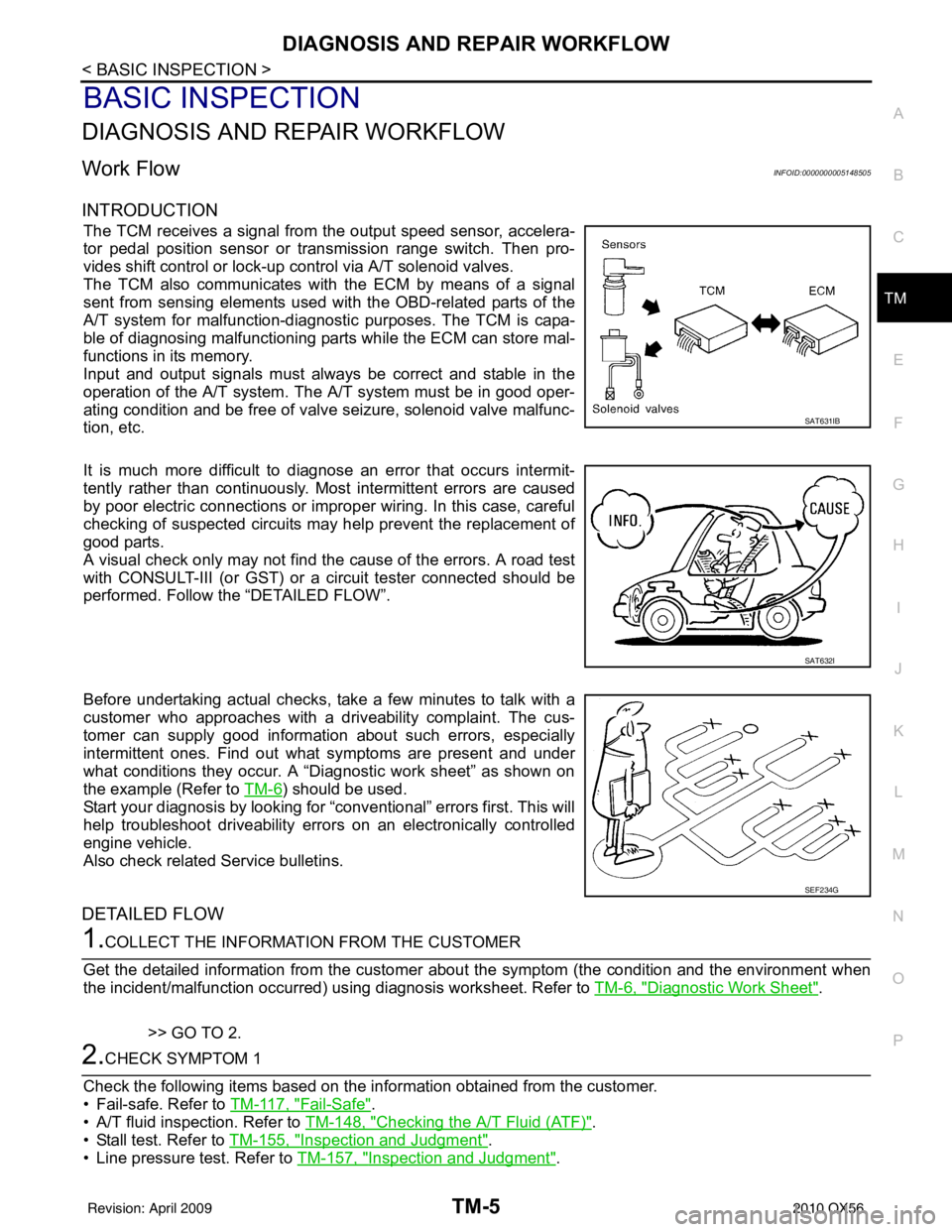
The TCM receives a signal from the output speed sensor, accelera-
tor pedal position sensor or transmission range switch. Then pro-
vides shift control or lock-up control via A/T solenoid valves.
The TCM also communicates with the ECM by means of a signal
sent from sensing elements used wit h the OBD-related parts of the
A/T system for malfunction-diagnostic purposes. The TCM is capa-
ble of diagnosing malfunctioning parts while the ECM can store mal-
functions in its memory.
Input and output signals must always be correct and stable in the
operation of the A/T system. T he A/T system must be in good oper-
ating condition and be free of valve seizure, solenoid valve malfunc-
tion, etc.
It is much more difficult to diagnose an error that occurs intermit-
tently rather than continuously. Most intermittent errors are caused
by poor electric connections or impr oper wiring. In this case, careful
checking of suspected circuits may help prevent the replacement of
good parts.
A visual check only may not find t he cause of the errors. A road test
with CONSULT-III (or GST) or a circuit tester connected should be
performed. Follow the “DETAILED FLOW”.
Before undertaking actual checks, take a few minutes to talk with a
customer who approaches with a driveability complaint. The cus-
tomer can supply good information about such errors, especially
intermittent ones. Find out what symptoms are present and under
what conditions they occur. A “Diagnostic work sheet” as shown on
the example (Refer to TM-6
) should be used.
Start your diagnosis by looking for “conventional” errors first. This will
help troubleshoot driveability errors on an electronically controlled
engine vehicle.
Also check related Service bulletins.
DETAILED FLOW
1.COLLECT THE INFORMATION FROM THE CUSTOMER
Get the detailed information from the customer about the symptom (the condition and the environment when
the incident/malfunction occurred) us ing diagnosis worksheet. Refer to TM-6, "
Diagnostic Work Sheet".
>> GO TO 2.
2.CHECK SYMPTOM 1
Check the following items based on the in formation obtained from the customer.
• Fail-safe. Refer to TM-117, "
Fail-Safe".
• A/T fluid inspection. Refer to TM-148, "
Checking the A/T Fluid (ATF)".
• Stall test. Refer to TM-155, "
Inspection and Judgment".
• Line pressure test. Refer to TM-157, "
Inspection and Judgment".
SAT631IB
SAT632I
SEF234G
Revision: April 20092010 QX56