2010 INFINITI QX56 trailer
[x] Cancel search: trailerPage 2534 of 4210
BCM (BODY CONTROL MODULE)INL-65
< ECU DIAGNOSIS >
C
DE
F
G H
I
J
K
M A
B
INL
N
O P
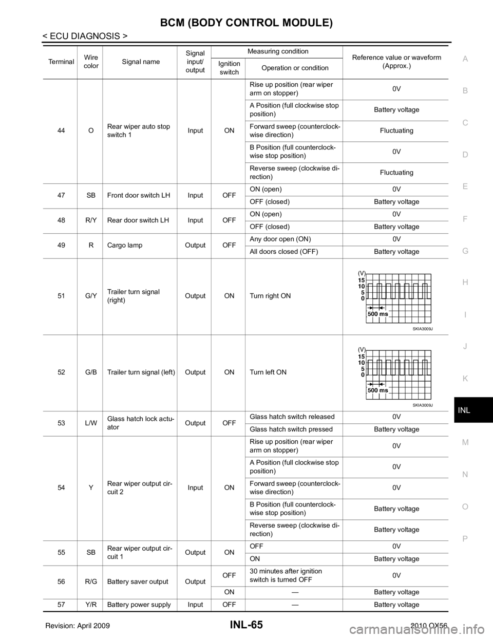
44 O Rear wiper auto stop
switch 1 Input ONRise up position (rear wiper
arm on stopper)
0V
A Position (full clockwise stop
position) Battery voltage
Forward sweep (counterclock-
wise direction) Fluctuating
B Position (full counterclock-
wise stop position) 0V
Reverse sweep (clockwise di-
rection) Fluctuating
47 SB Front door switch LH Input OFF ON (open)
0V
OFF (closed) Battery voltage
48 R/Y Rear door switch LH Input OFF ON (open)
0V
OFF (closed) Battery voltage
49 R Cargo lamp Output OFFAny door open (ON)
0V
All doors closed (OFF) Battery voltage
51 G/Y Trailer turn signal
(right) Output ON Turn right ON
52 G/B Trailer turn signal (left) Output ON Turn left ON
53 L/W Glass hatch lock actu-
ator
Output OFFGlass hatch switch released
0V
Glass hatch switch pressed Battery voltage
54 Y Rear wiper output cir-
cuit 2 Input ONRise up position (rear wiper
arm on stopper)
0V
A Position (full clockwise stop
position) 0V
Forward sweep (counterclock-
wise direction) 0V
B Position (full counterclock-
wise stop position) Battery voltage
Reverse sweep (clockwise di-
rection) Battery voltage
55 SB Rear wiper output cir-
cuit 1 Output ONOFF
0V
ON Battery voltage
56 R/G Battery saver output Output OFF
30 minutes after ignition
switch is turned OFF 0V
ON — Battery voltage
57 Y/R Battery power supply Input OFF —Battery voltage
Te r m i n a l
Wire
color Signal name Signal
input/
output Measuring condition
Reference value or waveform
(Approx.)
Ignition
switch Operation or condition
SKIA3009J
SKIA3009J
Revision: April 20092010 QX56
Page 2713 of 4210
PERIODIC MAINTENANCEMA-9
< ON-VEHICLE MAINTENANCE >
C
DE
F
G H
I
J
K L
M B
MA
N
O A
PERIODIC MAINTENANCE
Introduction of Periodic MaintenanceINFOID:0000000005145934
Two different maintenance schedules are provi
ded, and should be used, depending upon the conditions in
which the vehicle is mainly operated. After 60,000 miles (96,000 km) or 48 months, continue the periodic
maintenance at the same mileage or ti me intervals, whichever comes first.
Maintenance for Off-road Driving (4WD only)INFOID:0000000005145935
Whenever you drive off-road through sand, mud, or wa ter; more frequent maintenance may be required for the
following items:
Brake pads and rotors
Brake lines and hoses
Rear final drive oil, transmission fluid, and transfer fluid
Steering linkage
Drive shafts
Engine air cleaner filter
In-cabin microfilters
Schedule 1INFOID:0000000005145936
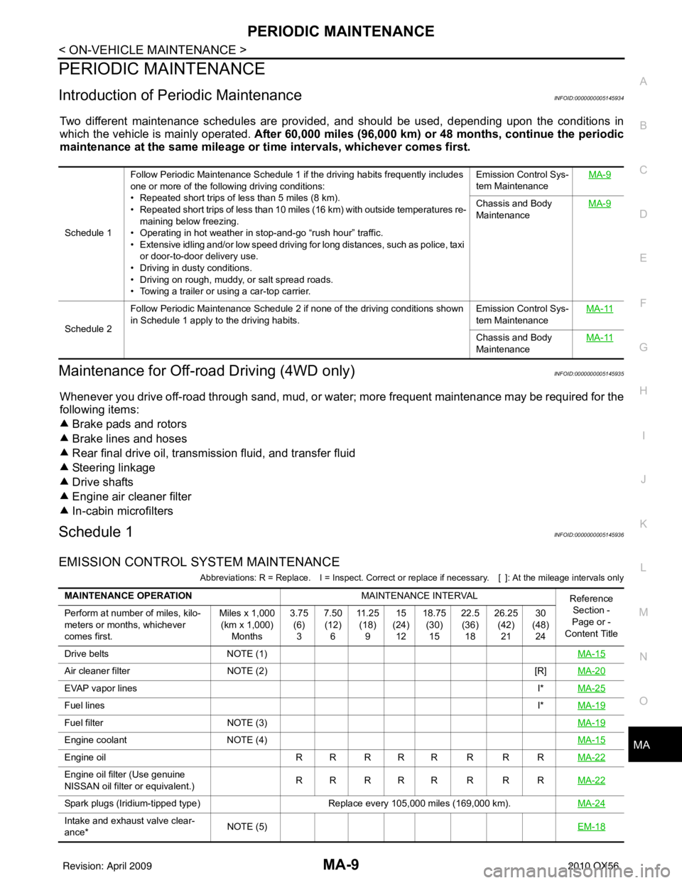
EMISSION CONTROL SYSTEM MAINTENANCE
Abbreviations: R = Replace. I = Ins pect. Correct or replace if necessary. [ ]: At the mileage intervals only
Schedule 1Follow Periodic Maintenance Schedule 1 if the driving habits frequently includes
one or more of the following driving conditions:
• Repeated short trips of less than 5 miles (8 km).
• Repeated short trips of less than 10 miles (16 km) with outside temperatures re-
maining below freezing.
• Operating in hot weather in stop-and-go “rush hour” traffic.
• Extensive idling and/or low speed driving for long distances, such as police, taxi
or door-to-door delivery use.
• Driving in dusty conditions.
• Driving on rough, muddy, or salt spread roads.
• Towing a trailer or using a car-top carrier. Emission Control Sys-
tem Maintenance
MA-9
Chassis and Body
Maintenance
MA-9
Schedule 2Follow Periodic Maintenance Schedule 2 if none of the driving conditions shown
in Schedule 1 apply to the driving habits.
Emission Control Sys-
tem MaintenanceMA-11Chassis and Body
Maintenance
MA-11
MAINTENANCE OPERATION
MAINTENANCE INTERVAL
Reference
Section -
Page or -
Content Title
Perform at number of miles, kilo-
meters or months, whichever
comes first. Miles x 1,000
(km x 1,000) Months 3.75
(6)3 7.50
(12) 6 11 . 2 5
(18) 9 15
(24) 12 18.75
(30)15 22.5
(36) 18 26.25
(42)21 30
(48) 24
Drive belts NOTE (1) MA-15
Air cleaner filterNOTE (2) [R]MA-20
EVAP vapor lines I*MA-25
Fuel lines I*MA-19
Fuel filter NOTE (3) MA-19
Engine coolantNOTE (4) MA-15
Engine oilR R R R R R R R MA-22
Engine oil filter (Use genuine
NISSAN oil filter or equivalent.)RR RRR R R R
MA-22
Spark plugs (Iridium-tipped type)Replace every 105,000 miles (169,000 km).MA-24
Intake and exhaust valve clear-
ance*NOTE (5)
EM-18
Revision: April 20092010 QX56
Page 2715 of 4210
PERIODIC MAINTENANCEMA-11
< ON-VEHICLE MAINTENANCE >
C
DE
F
G H
I
J
K L
M B
MA
N
O A
(1) If towing a trailer, or using a car-top carrier, or driving on rough or muddy roads, change (not just inspect) oil at every
30,000 miles
(48,000 km) or 24 months. Using automatic transmission fluid other than Ge nuine NISSAN Matic S ATF or Matic J ATF will cause
deterioration in drive ability and automatic transmission durability, and may damage the automatic transmission, which is not
covered by the INFINITI new vehicle limited warranty.
(2) Refer to “Tire rotation” under the “General maintenance” heading earlier in this section.
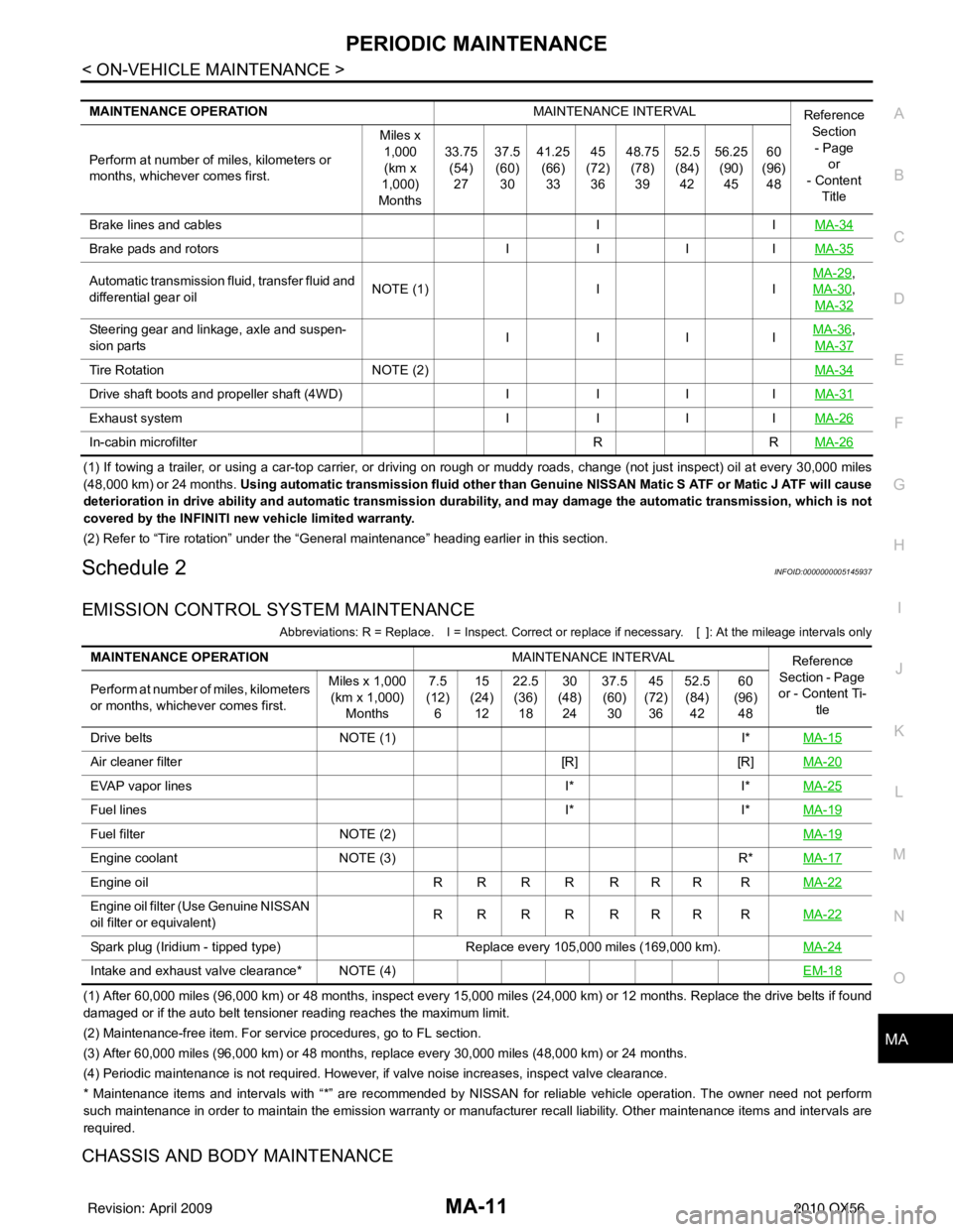
Schedule 2INFOID:0000000005145937
EMISSION CONTROL SYSTEM MAINTENANCE
Abbreviations: R = Replace. I = Ins pect. Correct or replace if necessary. [ ]: At the mileage intervals only
(1) After 60,000 miles (96,000 km) or 48 months, inspect every 15,000 miles (24,000 km) or 12 months. Replace the drive belts i f found
damaged or if the auto belt tensioner reading reaches the maximum limit.
(2) Maintenance-free item. For service procedures, go to FL section.
(3) After 60,000 miles (96,000 km) or 48 months, replace every 30,000 miles (48,000 km) or 24 months.
(4) Periodic maintenance is not required. However, if valve noise increases, inspect valve clearance.
* Maintenance items and inte rvals with “*” are recommended by NISSAN for reliable vehicle operation. The owner need not perform
such maintenance in order to maintain the emission warranty or manufacturer recall liability. Other maintenance items and inter vals are
required.
CHASSIS AND BODY MAINTENANCE
MAINTENANCE OPERATION MAINTENANCE INTERVAL
Reference
Section
- Page or
- Content
Title
Perform at number of miles, kilometers or
months, whichever comes first. Miles x
1,000(km x
1,000)
Months 33.75
(54)
27 37.5
(60)
30 41.25
(66)
33 45
(72)
36 48.75
(78)
39 52.5
(84)
42 56.25
(90)
45 60
(96)
48
Brake lines and cables IIMA-34
Brake pads and rotors IIIIMA-35
Automatic transmission fluid, transfer fluid and
differential gear oil NOTE (1)
IIMA-29,
MA-30
,
MA-32
Steering gear and linkage, axle and suspen-
sion parts IIII
MA-36,
MA-37
Tire Rotation NOTE (2) MA-34
Drive shaft boots and propeller shaft (4WD)IIIIMA-31
Exhaust system IIIIMA-26
In-cabin microfilter RRMA-26
MAINTENANCE OPERATION MAINTENANCE INTERVAL
Reference
Section - Page
or - Content Ti- tle
Perform at number of miles, kilometers
or months, whichever comes first. Miles x 1,000
(km x 1,000) Months 7.5
(12) 6 15
(24) 12 22.5
(36) 18 30
(48) 24 37.5
(60) 30 45
(72) 36 52.5
(84) 42 60
(96) 48
Drive belts NOTE (1) I*MA-15
Air cleaner filter [R][R]MA-20
EVAP vapor lines I*I*MA-25
Fuel lines I*I*MA-19
Fuel filter NOTE (2) MA-19
Engine coolantNOTE (3) R*MA-17
Engine oil R R R R R R R R MA-22
Engine oil filter (Use Genuine NISSAN
oil filter or equivalent)RRRR RRR R
MA-22
Spark plug (Iridium - tipped type) Replace every 105,000 miles (169,000 km).MA-24
Intake and exhaust valve clearance* NOTE (4) EM-18
Revision: April 20092010 QX56
Page 2830 of 4210
MWI-68
< ECU DIAGNOSIS >
BCM (BODY CONTROL MODULE)
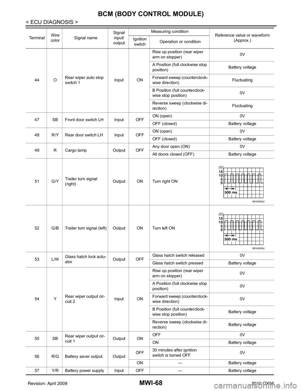
44 ORear wiper auto stop
switch 1 Input ONRise up position (rear wiper
arm on stopper)
0V
A Position (full clockwise stop
position) Battery voltage
Forward sweep (counterclock-
wise direction) Fluctuating
B Position (full counterclock-
wise stop position) 0V
Reverse sweep (clockwise di-
rection) Fluctuating
47 SB Front door switch LH Input OFF ON (open)
0V
OFF (closed) Battery voltage
48 R/Y Rear door switch LH Input OFF ON (open)
0V
OFF (closed) Battery voltage
49 R Cargo lamp Output OFFAny door open (ON)
0V
All doors closed (OFF) Battery voltage
51 G/Y Trailer turn signal
(right) Output ON Turn right ON
52 G/B Trailer turn signal (l eft) Output ON Turn left ON
53 L/W Glass hatch lock actu-
ator
Output OFFGlass hatch switch released
0V
Glass hatch switch pressed Battery voltage
54 Y Rear wiper output cir-
cuit 2 Input ONRise up position (rear wiper
arm on stopper)
0V
A Position (full clockwise stop
position) 0V
Forward sweep (counterclock-
wise direction) 0V
B Position (full counterclock-
wise stop position) Battery voltage
Reverse sweep (clockwise di-
rection) Battery voltage
55 SB Rear wiper output cir-
cuit 1 Output ONOFF
0V
ON Battery voltage
56 R/G Battery saver output Output OFF
30 minutes after ignition
switch is turned OFF 0V
ON — Battery voltage
57 Y/R Battery power supply Input OFF —Battery voltage
Te r m i n a l
Wire
color Signal name Signal
input/
output Measuring condition
Reference value or waveform
(Approx.)
Ignition
switch Operation or condition
SKIA3009J
SKIA3009J
Revision: April 20092010 QX56
Page 2844 of 4210
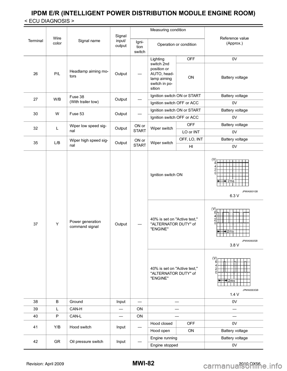
MWI-82
< ECU DIAGNOSIS >
IPDM E/R (INTELLIGENT POWER DISTRIBUTION MODULE ENGINE ROOM)
26 P/LHeadlamp aiming mo-
tors
Output —Lighting
switch 2nd
position or
AUTO, head-
lamp aiming
switch in po-
sition OFF
0V
ON Battery voltage
27 W/B Fuse 38
(With trailer tow)
Output —Ignition switch ON or START
Battery voltage
Ignition switch OFF or ACC 0V
30 W Fuse 53 Output —Ignition switch ON or START
Battery voltage
Ignition switch OFF or ACC 0V
32 L Wiper low speed sig-
nal
OutputON or
START Wiper switch OFF
Battery voltage
LO or INT 0V
35 L/B Wiper high speed sig-
nal
OutputON or
START Wiper switch OFF, LO, INT Battery voltage
HI 0V
37 Y Power generation
command signal Output —Ignition switch ON
6.3 V
40% is set on "Active test,"
"ALTERNATOR DUTY" of
"ENGINE" 3.8 V
40% is set on "Active test,"
"ALTERNATOR DUTY" of
"ENGINE" 1.4 V
38 B Ground Input ——0V
39 L CAN-H — ON— —
40 P CAN-L — ON— —
41 Y/B Hood switch Input —Hood closed OFF
0V
Hood open ON Battery voltage
42 GR Oil pressure switch Input — Engine running
Battery voltage
Engine stopped 0V
Te r m i n a l
Wire
color Signal name Signal
input/
output Measuring condition
Reference value(Approx.)
Igni-
tion
switch Operation or condition
JPMIA0001GB
JPMIA0002GB
JPMIA0003GB
Revision: April 20092010 QX56
Page 2845 of 4210
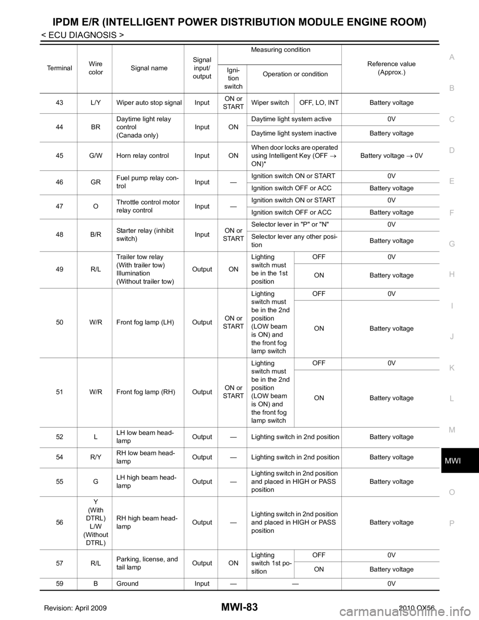
MWI
IPDM E/R (INTELLIGENT POWER DISTRIBUTION MODULE ENGINE ROOM)
MWI-83
< ECU DIAGNOSIS >
C
D E
F
G H
I
J
K L
M B A
O P
43 L/Y Wiper auto stop signal Input ON or
START Wiper switch OFF, LO, INT Battery voltage
44 BR Daytime light relay
control
(Canada only) Input ONDaytime light system active
0V
Daytime light system inactive Battery voltage
45 G/W Horn relay control Input ON When door locks are operated
using Intelligent Key (OFF
→
ON)* Battery voltage
→ 0V
46 GR Fuel pump relay con-
trol Input —Ignition switch ON or START
0V
Ignition switch OFF or ACC Battery voltage
47 O Throttle control motor
relay control Input —Ignition switch ON or START
0V
Ignition switch OFF or ACC Battery voltage
48 B/R Starter relay (inhibit
switch) Input
ON or
START Selector lever in "P" or "N"
0V
Selector lever any other posi-
tion Battery voltage
49 R/L Trailer tow relay
(With trailer tow)
Illumination
(Without trailer tow) Output ONLighting
switch must
be in the 1st
position OFF
0V
ON Battery voltage
50 W/R Front fog lamp (LH) Output ON or
START Lighting
switch must
be in the 2nd
position
(LOW beam
is ON) and
the front fog
lamp switch OFF
0V
ON Battery voltage
51 W/R Front fog lamp (RH) Output ON or
START Lighting
switch must
be in the 2nd
position
(LOW beam
is ON) and
the front fog
lamp switch OFF
0V
ON Battery voltage
52 L LH low beam head-
lamp
Output — Lighting switch in 2nd position Battery voltage
54 R/Y RH low beam head-
lamp Output — Lighting switch in 2nd position Battery voltage
55 G LH high beam head-
lamp Output —Lighting switch in 2nd position
and placed in HIGH or PASS
position Battery voltage
56 Y
(With
DTRL)
L/W
(Without DTRL) RH high beam head-
lamp
Output —Lighting switch in 2nd position
and placed in HIGH or PASS
position
Battery voltage
57 R/LPa
rking, license, and
tail lamp Output ONLighting
switch 1st po-
sition OFF
0V
ON Battery voltage
59 B Ground Input ——0V
Te r m i n a l
Wire
color Signal name Signal
input/
output Measuring condition
Reference value(Approx.)
Igni-
tion
switch Operation or condition
Revision: April 20092010 QX56
Page 2846 of 4210

MWI-84
< ECU DIAGNOSIS >
IPDM E/R (INTELLIGENT POWER DISTRIBUTION MODULE ENGINE ROOM)
*: When horn reminder is ON60 B/W
Rear window defog-
ger relay
OutputON or
START Rear defogger switch ON
Battery voltage
Rear defogger switch OFF 0V
61 BR Fuse 32
(With trailer tow) Output OFF
—Battery voltage
Te r m i n a l
Wire
color Signal name Signal
input/
output Measuring condition
Reference value(Approx.)
Igni-
tion
switch Operation or condition
Revision: April 20092010 QX56
Page 2881 of 4210
![INFINITI QX56 2010 Factory Service Manual PCS-6
< FUNCTION DIAGNOSIS >[IPDM E/R]
RELAY CONTROL SYSTEM
System Description
INFOID:0000000005146497
IPDM E/R activates the internal cont rol circuit to perform the relay ON-OFF control according to INFINITI QX56 2010 Factory Service Manual PCS-6
< FUNCTION DIAGNOSIS >[IPDM E/R]
RELAY CONTROL SYSTEM
System Description
INFOID:0000000005146497
IPDM E/R activates the internal cont rol circuit to perform the relay ON-OFF control according to](/manual-img/42/57032/w960_57032-2880.png)
PCS-6
< FUNCTION DIAGNOSIS >[IPDM E/R]
RELAY CONTROL SYSTEM
System Description
INFOID:0000000005146497
IPDM E/R activates the internal cont rol circuit to perform the relay ON-OFF control according to the input sig-
nals from various sensors and the request signals received from control units via CAN communication.
CAUTION:
IPDM E/R integrated relays cannot be removed.
Control relay Input/outputTransmit unit Control partReference
page
Front fog lamp relay Front fog lamp request signal BCM (CAN) Front fog lamps EXL-14
• Headlamp LH high relay
• Headlamp RH high relay
• Headlamp low relay• High beam request signal LH
• High beam request signal RH
• Low beam request signal
BCM (CAN)• Headlamp high LH
• Headlamp high RH
• Headlamp low EXL-7
EXL-7
Tail lamp relay
Position light request signal BCM (CAN)•Parking lamps
• License plate lamps
•Tail lamps
• Trailer tow relay
• Illumination system EXL-17
• Front wiper relay
• Front wiper high relay
Front wiper request signal
BCM (CAN) Front wiper motor WW-4
Rear window defogger relay Rear window defogger request signal BCM (CAN) Rear window defogger WW-8
A/C relayA/C request signal •BCM (CAN)
•ECM (CAN)
A/C compressor
HAC-20
Starter relay Ignition switch START signal TCMStarter motor STR-8
Cooling fan relay Cooling fan request signal ECM (CAN) Cooling fan relay EC-36
Heated mirror relayHeated mirror request sign alBCM (CAN) Door mirrors DEF-4
ECM relayECM relay control signal ECM (CAN) ECM relay EC-21
Throttle control motor relay Throttle control moto r control signal ECM (CAN) Throttle control motor re-
layEC-28
Fuel pump relay
Fuel pump request signal ECM (CAN) Fuel pump EC-28
Ignition relayIgnition switch ON signal Ignition switch Ignition relay EC-31
Revision: April 20092010 QX56