2010 INFINITI QX56 length
[x] Cancel search: lengthPage 1944 of 4210
ENGINE UNITEM-93
< DISASSEMBLY AND ASSEMBLY >
C
DE
F
G H
I
J
K L
M A
EM
NP
O
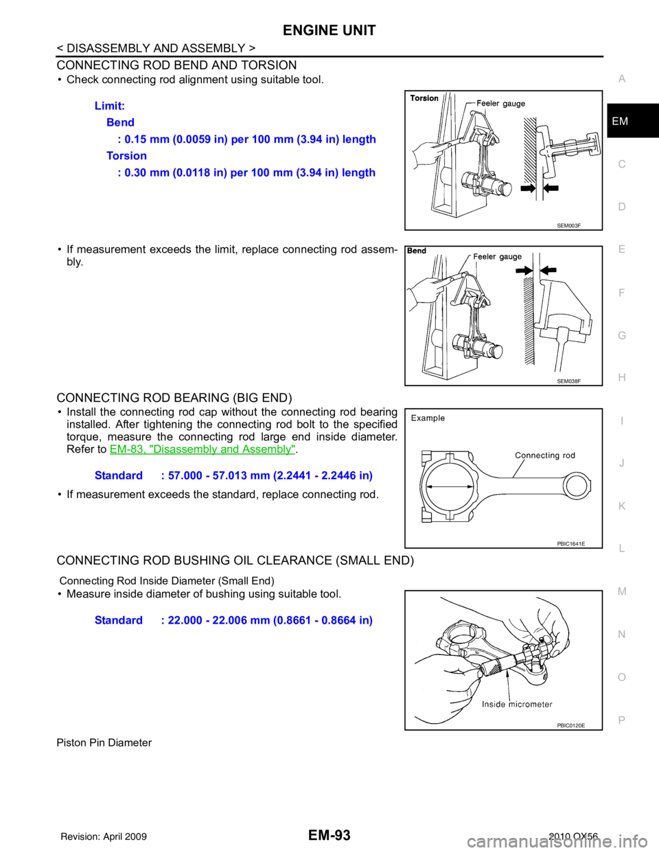
CONNECTING ROD BEND AND TORSION
• Check connecting rod alignment using suitable tool.
• If measurement exceeds the limi
t, replace connecting rod assem-
bly.
CONNECTING ROD BEARING (BIG END)
• Install the connecting rod cap without the connecting rod bearing installed. After tightening the connecting rod bolt to the specified
torque, measure the connecting rod large end inside diameter.
Refer to EM-83, "
Disassembly and Assembly".
• If measurement exceeds the standard, replace connecting rod.
CONNECTING ROD BUSHING OIL CLEARANCE (SMALL END)
Connecting Rod Inside Diameter (Small End)
• Measure inside diameter of bushing using suitable tool.
Piston Pin Diameter
Limit: Bend: 0.15 mm (0.0059 in) per 100 mm (3.94 in) length
To r s i o n : 0.30 mm (0.0118 in) per 100 mm (3.94 in) length
SEM003F
SEM038F
Standard : 57.000 - 57.013 mm (2.2441 - 2.2446 in)
PBIC1641E
Standard : 22.000 - 22.006 mm (0.8661 - 0.8664 in)
PBIC0120E
Revision: April 20092010 QX56
Page 1962 of 4210
SERVICE DATA AND SPECIFICATIONS (SDS)EM-111
< SERVICE DATA AND SPECIFICATIONS (SDS)
C
DE
F
G H
I
J
K L
M A
EM
NP
O
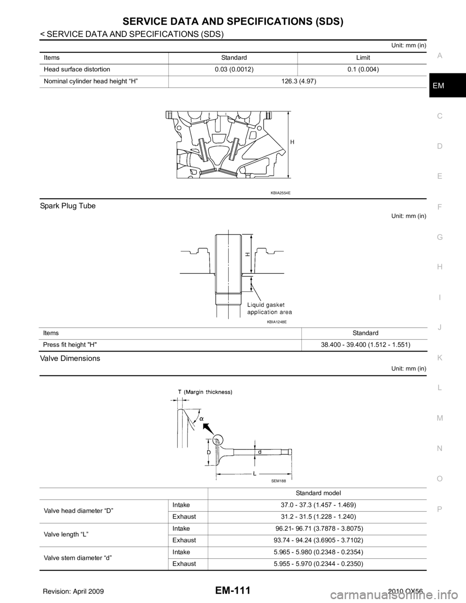
Unit: mm (in)
Spark Plug Tube
Unit: mm (in)
Valve Dimensions
Unit: mm (in)
Items
StandardLimit
Head surface distortion 0.03 (0.0012)0.1 (0.004)
Nominal cylinder head height “H” 126.3 (4.97)
KBIA2554E
Items Standard
Press fit height "H" 38.400 - 39.400 (1.512 - 1.551)
KBIA1248E
Standard model
Valve head diameter “D” Intake
37.0 - 37.3 (1.457 - 1.469)
Exhaust 31.2 - 31.5 (1.228 - 1.240)
Valve length “L” Intake
96.21- 96.71 (3.7878 - 3.8075)
Exhaust 93.74 - 94.24 (3.6905 - 3.7102)
Valve stem diameter “d” Intake
5.965 - 5.980 (0.2348 - 0.2354)
Exhaust 5.955 - 5.970 (0.2344 - 0.2350)
SEM188
Revision: April 20092010 QX56
Page 1963 of 4210
EM-112
< SERVICE DATA AND SPECIFICATIONS (SDS)
SERVICE DATA AND SPECIFICATIONS (SDS)
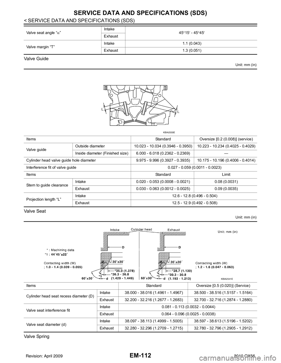
Valve Guide
Unit: mm (in)
Va l v e S e a t
Unit: mm (in)
Valve Spring
Valve seat angle “α” Intake
45°15 ′ - 45 °45 ′
Exhaust
Valve margin “T” Intake
1.1 (0.043)
Exhaust 1.3 (0.051)
Items StandardOversize [0.2 (0.008)] (service)
Va l v e g u i d e Outside diameter
10.023 - 10.034 (0.3946 - 0.3950) 10.223 - 10.234 (0.4025 - 0.4029)
Inside diameter (Finished size) 6.000 - 6.018 (0.2362 - 0.2369) —
Cylinder head valve guide hole diameter 9.975 - 9.996 (0.3927 - 0.3935) 10.175 - 10.196 (0.4006 - 0.4014)
Interference fit of valve guide 0.027 - 0.059 (0.0011 - 0.0023)
Items StandardLimit
Stem to guide clearance Intake
0.020 - 0.053 (0.0008 - 0.0021) 0.08 (0.0031)
Exhaust 0.030 - 0.063 (0.0012 - 0.0025) 0.09 (0.0035)
Projection length “L” Intake
12.6 - 12.8 (0.496 - 0.504)
Exhaust 12.5 - 12.9 (0.492 - 0.508)
KBIA2555E
Items StandardOversize [0.5 (0.020)] (Service)
Cylinder head seat recess diameter (D) Intake 38.000 - 38.016 (1.4961 - 1.4967) 38.500 - 38.516 (1.5157 - 1.5164)
Exhaust 32.200 - 32.216 (1.2677 - 1.2683) 32.700 - 32.716 (1.2874 - 1.2880)
Valve seat interference fit Intake
0.081 - 0.113 (0.0032 - 0.0044)
Exhaust 0.064 - 0.096 (0.0025 - 0.0038)
Valve seat diameter (d) Intake 38.097 - 38.113 (1.4999 - 1.5005) 38.597 - 38.613 (1.5196 - 1.5202)
Exhaust 32.280 - 32.296 (1.2709 - 1.2715) 32.780 - 32.796 (1.2905 - 1.2912)
KBIA2541E
Revision: April 20092010 QX56
Page 1984 of 4210
EXL-8
< FUNCTION DIAGNOSIS >
HEADLAMP
A Xenon type headlamp is adapted to the low beam headlamps. Xenon bulbs do not use a filament. Instead,
they produce light when a high voltage current is pa ssed between two tungsten electrodes through a mixture
of Xenon (an inert gas) and certain other metal halides. In addition to added lighting power, electronic control
of the power supply gives the headlamps stable quality and tone color. Following are some of the advantages
of the Xenon type headlamp.
• The light produced by the headlamps is a white color comparable to sunlight that is easy on the eyes.
• Light output is nearly double that of halogen headlamps, affording increased area of illumination.
• The light features a high relative spectral distribution at wavelengths to which the human eye is most sensi- tive. This means that even in the rain, more light is reflected back from the road surface toward the vehicle,
for added visibility.
• Power consumption is approximately 25 percent less than halogen headlamps, reducing battery load.
HIGH BEAM OPERATION/FLASH-TO-PASS OPERATION
With the combination switch (lighting and turn signal switch) in the 2ND position and placed in HIGH position,
the BCM receives input requesting the headlamp high beams to illuminate. The flash to pass feature can be
used any time and also sends a signal to the BCM. This input is communicated to the IPDM E/R via the CAN
communication lines. The CPU of the combination meter c ontrols the ON/OFF status off the HIGH BEAM indi-
cator. The CPU of the IPDM E/R controls the headlamp high relay coil which supplies power to the high beam
headlamps.
The combination meter receives a high beam request signal (ON) via the CAN communication lines and turns
the high beam indicator lamp ON.
EXTERIOR LAMP BATTERY SAVER CONTROL
With the combination switch (lighting and turn signal switch) in the 2nd position and the ignition switch is
turned from ON or ACC to OFF, the battery saver feature is activated.
Under this condition, the headlamps remain illuminated for 5 minutes unless the lighting switch position is
changed. If the lighting switch position is changed, then the headlamps are turned off.
This setting can be changed by CONSULT-III. Refer to BCS-22, "
HEADLAMP : CONSULT-III Function (BCM -
HEAD LAMP)".
Revision: April 20092010 QX56
Page 2180 of 4210
FAX-14
< DISASSEMBLY AND ASSEMBLY >
DRIVE SHAFT
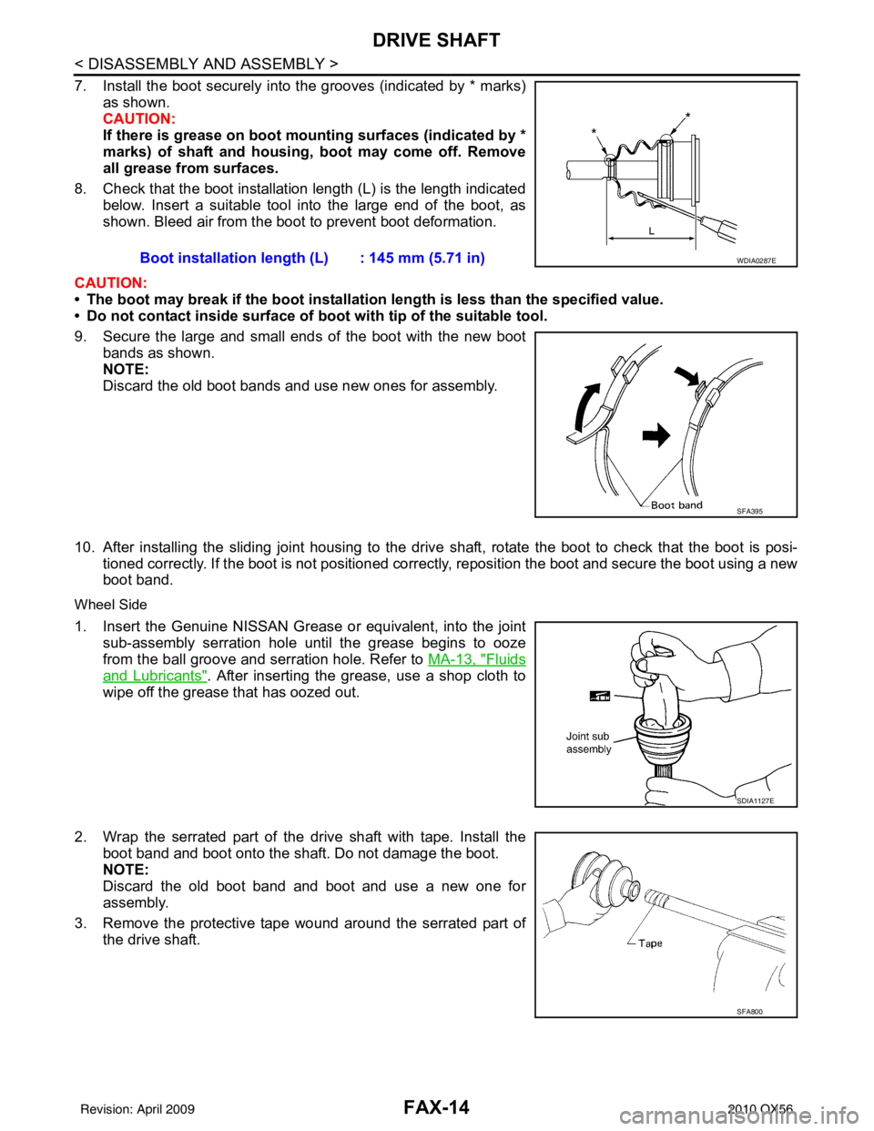
7. Install the boot securely into the grooves (indicated by * marks)as shown.
CAUTION:
If there is grease on boot mounting surfaces (indicated by *
marks) of shaft and housing, boot may come off. Remove
all grease from surfaces.
8. Check that the boot installation length (L) is the length indicated below. Insert a suitable tool into the large end of the boot, as
shown. Bleed air from the boot to prevent boot deformation.
CAUTION:
• The boot may break if the boot installati on length is less than the specified value.
• Do not contact inside surface of boot with tip of the suitable tool.
9. Secure the large and small ends of the boot with the new boot bands as shown.
NOTE:
Discard the old boot bands and use new ones for assembly.
10. After installing the sliding joint housing to the drive shaft, rotate the boot to check that the boot is posi-
tioned correctly. If the boot is not positioned correctly , reposition the boot and secure the boot using a new
boot band.
Wheel Side
1. Insert the Genuine NISSAN Grease or equivalent, into the joint
sub-assembly serration hole until the grease begins to ooze
from the ball groove and serration hole. Refer to MA-13, "
Fluids
and Lubricants". After inserting the grease, use a shop cloth to
wipe off the grease that has oozed out.
2. Wrap the serrated part of the drive shaft with tape. Install the boot band and boot onto the shaft. Do not damage the boot.
NOTE:
Discard the old boot band and boot and use a new one for
assembly.
3. Remove the protective tape wound around the serrated part of the drive shaft. Boot installation length (L) : 145 mm (5.71 in)
WDIA0287E
SFA395
SDIA1127E
SFA800
Revision: April 20092010 QX56
Page 2181 of 4210
DRIVE SHAFTFAX-15
< DISASSEMBLY AND ASSEMBLY >
CEF
G H
I
J
K L
M A
B
FA X
N
O P
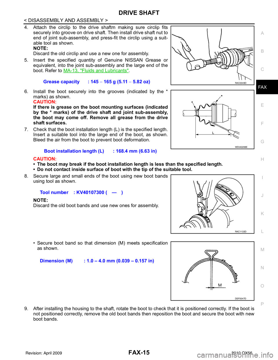
4. Attach the circlip to the drive shaftm making sure circlip fits securely into groove on drive shaft. Then install drive shaft nut to
end of joint sub-assembly, and press-fit the circlip using a suit-
able tool as shown.
NOTE:
Discard the old circlip and use a new one for assembly.
5. Insert the specified quantity of Genuine NISSAN Grease or equivalent, into the joint sub-assembly and the large end of the
boot. Refer to MA-13, "
Fluids and Lubricants".
6. Install the boot securely into the grooves (indicated by the * marks) as shown.
CAUTION:
If there is grease on the bo ot mounting surfaces (indicated
by the * marks) of the drive shaft and joint sub-assembly,
the boot may come off. Remove all grease from the drive
shaft surfaces.
7. Check that the boot installation length (L) is the specified length. Insert a suitable tool into the large end of the boot, as shown.
Bleed the air from the boot to prevent boot deformation.
CAUTION:
• The boot may break if the boot installation length is less than the specified length.
• Do not contact inside surface of boot with the tip of the suitable tool.
8. Secure large and small ends of the boot using new boot bands using tool as shown.
NOTE:
Discard the old boot bands and use new ones for assembly.
• Secure boot band so that dimension (M) meets specificationas shown.
9. After installing the housing to the shaft, rotate the boot to check that it is positioned correctly. If the boot is
not positioned correctly, remove the old boot bands then reposition the boot and secure the boot with new
boot bands. Grease capacity : 145
− 165 g (5.11 − 5.82 oz)
RAC0049D
Boot installation length (L) : 168.4 mm (6.63 in)
Tool number : KV40107300 ( — )
WDIA0288E
RAC1133D
Dimension (M) : 1.0 – 4.0 mm (0.039 – 0.157 in)
DSF0047D
Revision: April 20092010 QX56
Page 2182 of 4210
FAX-16
< SERVICE DATA AND SPECIFICATIONS (SDS)
SERVICE DATA AND SPECIFICATIONS (SDS)
SERVICE DATA AND SPECIFICATIONS (SDS)
SERVICE DATA AND SPECIFICATIONS (SDS)
Wheel BearingINFOID:0000000005148947
Drive ShaftINFOID:0000000005148948
Boot BandsINFOID:0000000005148949
Unit: mm (in)
Wheel bearing axial end play0.05 mm (0.002 in) or less
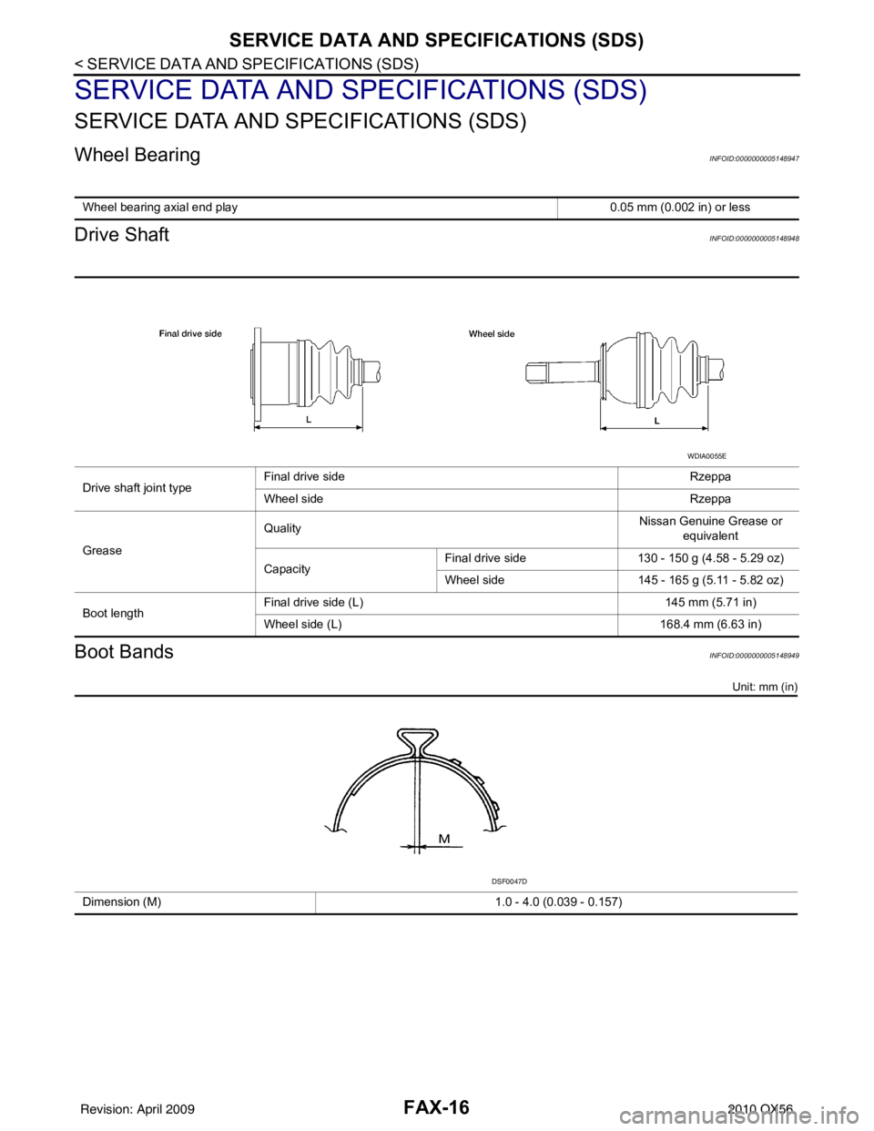
Drive shaft joint typeFinal drive side Rzeppa
Wheel side
Rzeppa
Grease Quality
Nissan Genuine Grease or
equivalent
Capacity Final drive side
130 - 150 g (4.58 - 5.29 oz)
Wheel side 145 - 165 g (5.11 - 5.82 oz)
Boot length Final drive side (L)
145 mm (5.71 in)
Wheel side (L) 168.4 mm (6.63 in)
WDIA0055E
Dimension (M) 1.0 - 4.0 (0.039 - 0.157)
DSF0047D
Revision: April 20092010 QX56
Page 2207 of 4210
FSU-8
< ON-VEHICLE MAINTENANCE >
ON-VEHICLE SERVICE
• Always perform the following procedure on a flat surface.
• Make sure that no person is in front of the vehicle before pushing it.
1. Bounce the front of vehicle up and down to stabilize the vehicle height (posture).
2. Push the vehicle straight ahead about 5 m (16 ft).
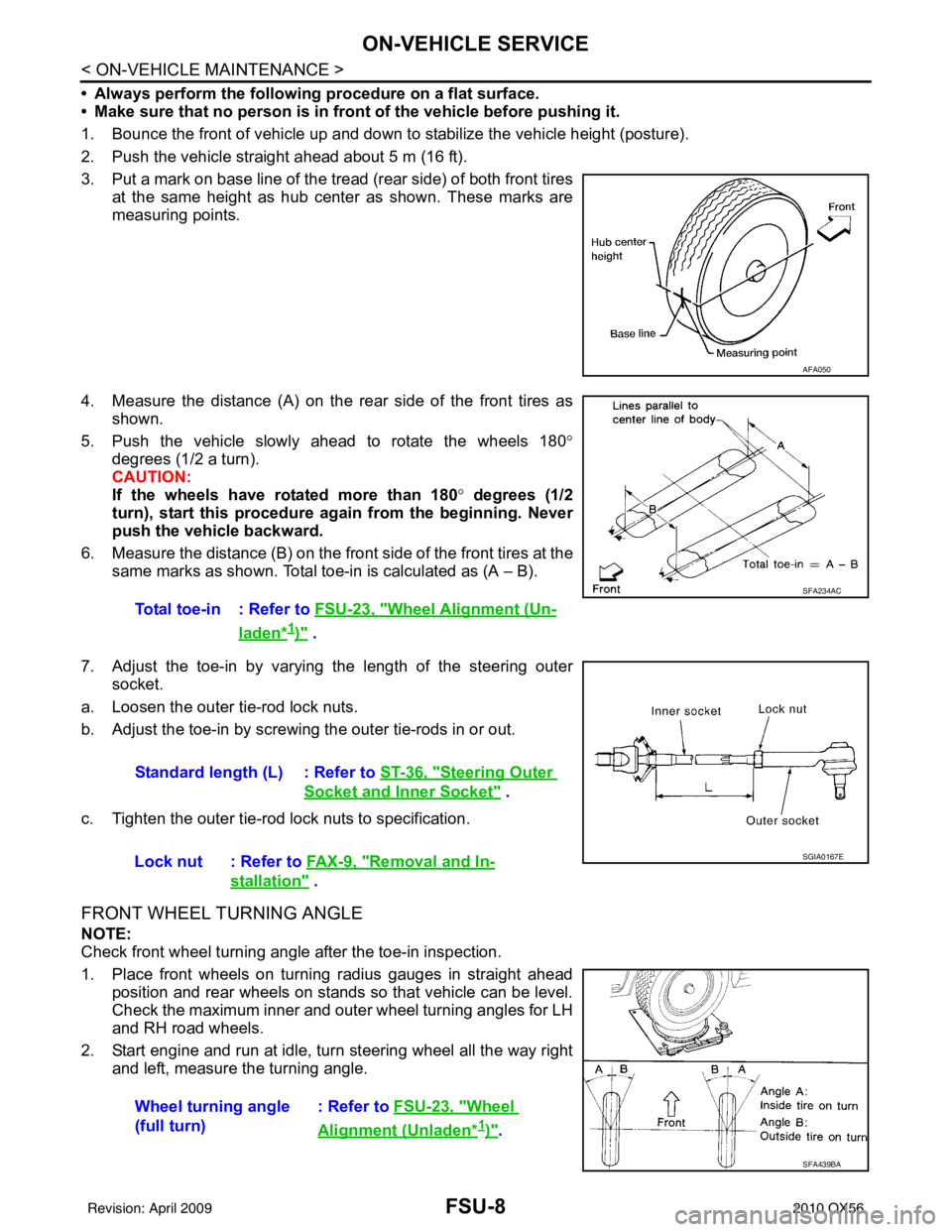
3. Put a mark on base line of the tread (rear side) of both front tires at the same height as hub center as shown. These marks are
measuring points.
4. Measure the distance (A) on the rear side of the front tires as shown.
5. Push the vehicle slowly ahead to rotate the wheels 180 °
degrees (1/2 a turn).
CAUTION:
If the wheels have rotated more than 180 ° degrees (1/2
turn), start this procedure again from the beginning. Never
push the vehicle backward.
6. Measure the distance (B) on the front side of the front tires at the
same marks as shown. Total toe-in is calculated as (A – B).
7. Adjust the toe-in by varying the length of the steering outer socket.
a. Loosen the outer tie-rod lock nuts.
b. Adjust the toe-in by screwing the outer tie-rods in or out.
c. Tighten the outer tie-rod lock nuts to specification.
FRONT WHEEL TURNING ANGLE
NOTE:
Check front wheel turning angle after the toe-in inspection.
1. Place front wheels on turning radius gauges in straight ahead position and rear wheels on stands so that vehicle can be level.
Check the maximum inner and outer wheel turning angles for LH
and RH road wheels.
2. Start engine and run at idle, turn steering wheel all the way right and left, measure the turning angle.
AFA050
Total toe-in : Refer to FSU-23, "Wheel Alignment (Un-
laden*1)" .
SFA234AC
Standard length (L) : Refer to ST-36, "Steering Outer
Socket and Inner Socket" .
Lock nut : Refer to FA X - 9 , "
Removal and In-
stallation" .
SGIA0167E
Wheel turning angle
(full turn) : Refer to
FSU-23, "Wheel
Alignment (Unladen*1)".
SFA439BA
Revision: April 20092010 QX56