2010 INFINITI QX56 checking oil
[x] Cancel search: checking oilPage 1764 of 4210
![INFINITI QX56 2010 Factory Service Manual IGNITION SIGNALEC-411
< COMPONENT DIAGNOSIS > [VK56DE]
C
D
E
F
G H
I
J
K L
M A
EC
NP
O
7. Remove fuel pump fuse in IPDM E/R to release fuel pressure.
NOTE:
Do not use CONSULT-III to release fuel press INFINITI QX56 2010 Factory Service Manual IGNITION SIGNALEC-411
< COMPONENT DIAGNOSIS > [VK56DE]
C
D
E
F
G H
I
J
K L
M A
EC
NP
O
7. Remove fuel pump fuse in IPDM E/R to release fuel pressure.
NOTE:
Do not use CONSULT-III to release fuel press](/manual-img/42/57032/w960_57032-1763.png)
IGNITION SIGNALEC-411
< COMPONENT DIAGNOSIS > [VK56DE]
C
D
E
F
G H
I
J
K L
M A
EC
NP
O
7. Remove fuel pump fuse in IPDM E/R to release fuel pressure.
NOTE:
Do not use CONSULT-III to release fuel pressure, or fuel pres-
sure applies again during the following procedure.
8. Start engine.
9. After engine stalls, crank it two or three times to release all fuel pressure.
10. Turn ignition switch OFF.
11. Remove all ignition coil harness connectors to avoid the electri- cal discharge from the ignition coils.
12. Remove ignition coil and spark plug of the cylinder to be checked.
13. Crank engine for 5 seconds or more to remove combustion gas in the cylinder.
14. Connect spark plug and harness connector to ignition coil.
15. Fix ignition coil using a rope etc. with gap of 13 - 17 mm (0.52 - 0.66 in) between the edge of the spark plug and grounded metal
portion as shown in the figure.
16. Crank engine for about 3 seconds, and check whether spark is generated between the spark plug and the grounded metal por-
tion.
CAUTION:
• Do not approach to the spark plug and the ignition coil
within 50cm. Be careful not to get an electrical shock
while checking, because the el ectrical discharge voltage
becomes 20kV or more.
• It might cause to damage the ignition coil if the gap of more than 17 mm (0.66 in) is taken.
NOTE:
When the gap is less than 13 mm (0.52 in), the sp ark might be generated even if the coil is mal-
functioning.
17. If NG, replace ignition coil with power transistor.
CONDENSER-1
1. Turn ignition switch OFF.
2. Disconnect condenser-1 harness connector.
3. Check resistance between condenser-1 terminals 1 and 2. Spark should be generated.
BBIA0380E
PBIB2325E
Resistance
Above 1 MΩ [at 25 °C (77 °F)]
PBIB0794E
Revision: April 20092010 QX56
Page 1852 of 4210
EM-1
ENGINE
C
DE
F
G H
I
J
K L
M
SECTION EM
A
EM
N
O P
CONTENTS
ENGINE MECHANICAL
PRECAUTION ....... ........................................3
PRECAUTIONS .............................................. .....3
Precaution for Supplemental Restraint System
(SRS) "AIR BAG" and "SEAT BELT PRE-TEN-
SIONER" ............................................................. ......
3
Precaution Necessary for Steering Wheel Rota-
tion After Battery Disconnect ............................... ......
3
Precaution for Drain Engine Coolant .........................4
Precaution for Disconnecting Fuel Piping .................4
Precaution for Removal and Disassembly ................4
Precaution for Inspection, Repair and Replace-
ment .................................................................... ......
4
Precaution for Assembly and Installation ..................4
Parts Requiring Angular Tightening ..........................4
Precaution for Liquid Gasket ............................... ......5
PREPARATION ............................................6
PREPARATION .............................................. .....6
Special Service Tool ........................................... ......6
Commercial Service Tool ..........................................8
FUNCTION DIAGNOSIS ..............................10
NOISE, VIBRATION, AND HARSHNESS
(NVH) TROUBLESHOOTING ........................ ....
10
NVH Troubleshooting - Engine Noise ................. ....10
Use the Chart Below to Help You Find the Cause
of the Symptom .......................................................
11
ON-VEHICLE MAINTENANCE ....................13
DRIVE BELTS ................................................ ....13
Exploded View .................................................... ....13
Checking Drive Belts ...............................................13
Removal and Installation .........................................13
Drive Belt Auto Tensioner and Idler Pulley ......... ....14
AIR CLEANER FILTER ......................................15
Exploded View .................................................... ....15
Removal and Installation (Viscous paper type) .......15
SPARK PLUG ...................................................16
Exploded View ..................................................... ....16
Removal and Installation .........................................16
CAMSHAFT VALVE CLEARANCE ..................18
Valve Clearance ......................................................18
COMPRESSION PRESSURE ...........................23
Checking Compression Pressure ............................23
ON-VEHICLE REPAIR .................................24
ENGINE ROOM COVER ...................................24
Removal and Installation ..................................... ....24
AIR CLEANER AND AIR DUCT .......................25
Exploded View .........................................................25
Removal and Installation .........................................25
INTAKE MANIFOLD .........................................26
Exploded View .........................................................26
Removal and Installation .........................................26
EXHAUST MANIFOLD AND THREE WAY
CATALYST ........................................................
30
Exploded View .........................................................30
Removal and Installation .........................................30
OIL PAN AND OIL STRAINER .........................33
Exploded View .........................................................33
Removal and Installation .........................................33
IGNITION COIL .................................................37
Exploded View .........................................................37
Removal and Installation .........................................37
ROCKER COVER .............................................38
Exploded View .........................................................38
Removal and Installation .........................................38
FUEL INJECTOR AND FUEL TUBE ................40
Exploded View .........................................................40
Removal and Installation .........................................40
Revision: April 20092010 QX56
Page 1874 of 4210
COMPRESSION PRESSUREEM-23
< ON-VEHICLE MAINTENANCE >
C
DE
F
G H
I
J
K L
M A
EM
NP
O
COMPRESSION PRESSURE
Checking Compression PressureINFOID:0000000005148983
1. Warm up the engine thoroughly. Then stop the engine.
2. Release the fuel pressure. Refer to EC-489, "
Fuel Pressure Check".
CAUTION:
If CONSULT-III is not used to release fuel pressure leave the fuel pump fuse disconnected until
step 7.
3. Remove the spark plug from each cylinder. Refer to EM-16, "
Removal and Installation".
4. Connect the engine tachometer (not required in use of CONSULT-III).
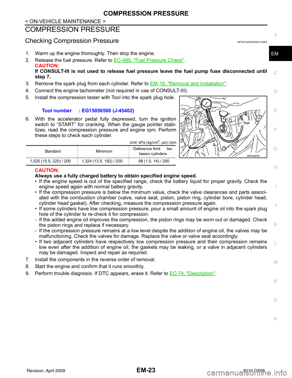
5. Install the compression tester with Tool into the spark plug hole.
6. With the accelerator pedal fully depressed, turn the ignition switch to “START” for cranking. When the gauge pointer stabi-
lizes, read the compression pressure and engine rpm. Perform
these steps to check each cylinder.
Unit: kPa (kg/cm2, psi) /rpm
CAUTION:
Always use a fully charged battery to obtain specified engine speed.
• If the engine speed is out of the specified range, check the battery liquid for proper gravity. Check the engine speed again with normal battery gravity.
• If the compression pressure is below the minimum value, check the valve clearances and parts associ-
ated with the combustion chamber (valve, valve seat , piston, piston ring, cylinder bore, cylinder head,
cylinder head gasket). After checking, measure the compression pressure again.
• If some cylinders have low compression pressure, pour a small amount of engine oil into the spark plug hole of the cylinder to re-check it for compression.
- If the added engine oil improves the compression, t he piston rings may be worn out or damaged. Check
the piston rings and replace if necessary.
- If the compression pressure remains at a low level despite the addition of engine oil, the valves may be malfunctioning. Check the valves for damage. Replace the valve or valve seat accordingly.
• If two adjacent cylinders have respectively low compression pressure and their compression remains low even after the addition of engine oil, the gaskets may be leaking, or a valve in adjacent cylinders
may be damaged. Inspect and repair as required.
7. Install the components in the reverse order of removal.
8. Start the engine and confirm that it runs smoothly.
9. Perform trouble diagnosis. If DTC appears, erase it. Refer to EC-74, "
Description".
Tool number : EG15050500 (J-45402)
Standard
MinimumDeference limit be-
tween cylinders
1,520 (15.5, 220) / 200 1,324 (13.5, 192) / 200 98 (1.0, 14) / 200WBIA0605E
Revision: April 20092010 QX56
Page 1893 of 4210
EM-42
< ON-VEHICLE REPAIR >
FUEL INJECTOR AND FUEL TUBE
• Lubricate O-ring with new engine oil.
• Do not clean O-ring with solvent.
• Make sure that O-ring and its mating part are free of foreign material.
• When installing O-ring, be careful not to scratch it with tool or fingernails. Also be careful not to
twist or stretch O-ring. If O-ring was stretc hed while it was being attached, do not insert it
quickly into fuel tube.
• Insert O-ring straight into fuel tube. Do not angle or twist it.
3. Install fuel injector to fuel tube.
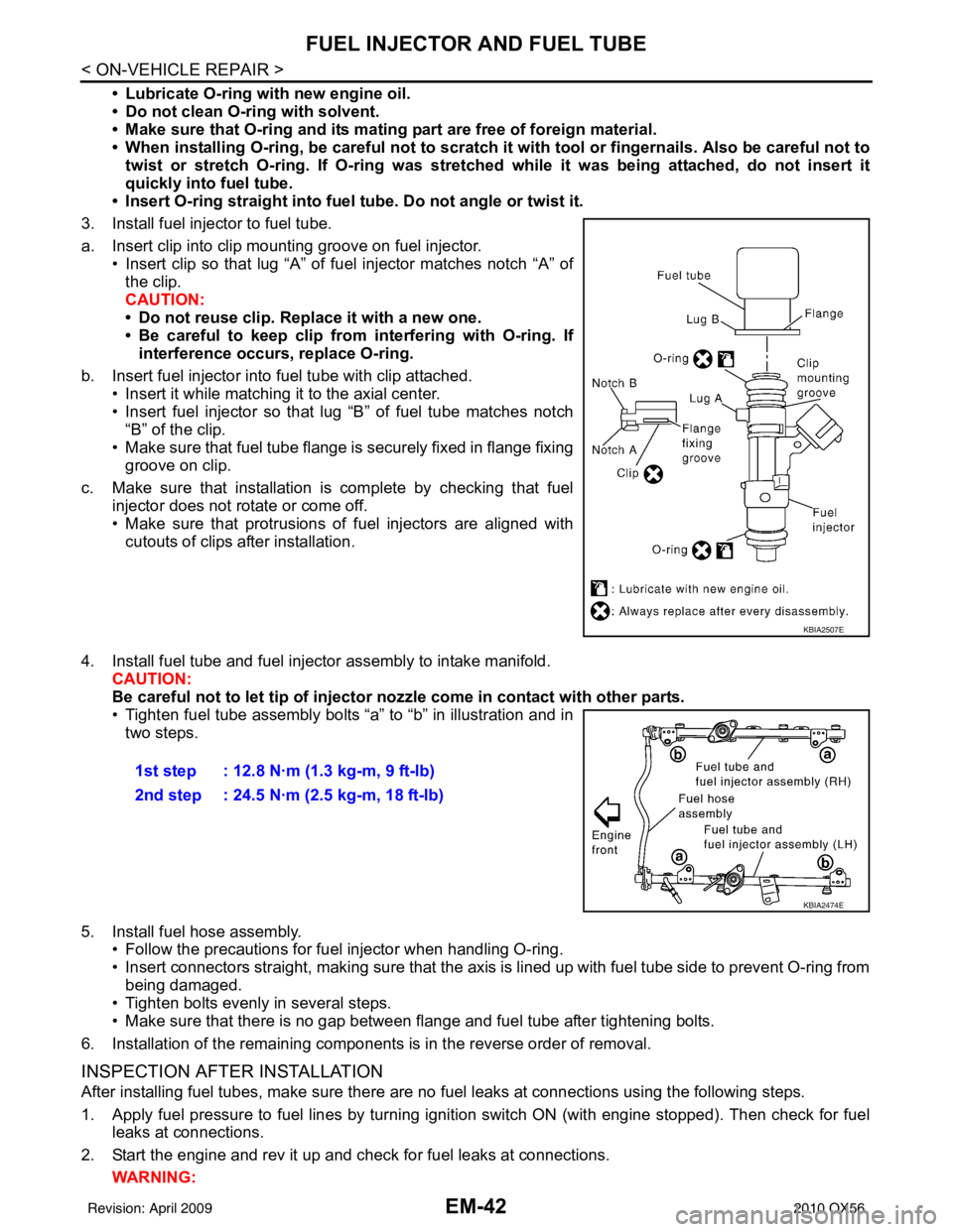
a. Insert clip into clip mounting groove on fuel injector. • Insert clip so that lug “A” of fuel injector matches notch “A” ofthe clip.
CAUTION:
• Do not reuse clip. Replace it with a new one.
• Be careful to keep clip from interfering with O-ring. Ifinterference occurs, replace O-ring.
b. Insert fuel injector into fuel tube with clip attached. • Insert it while matching it to the axial center.
• Insert fuel injector so that lug “B” of fuel tube matches notch
“B” of the clip.
• Make sure that fuel tube flange is securely fixed in flange fixing groove on clip.
c. Make sure that installation is complete by checking that fuel injector does not rotate or come off.
• Make sure that protrusions of fuel injectors are aligned withcutouts of clips after installation.
4. Install fuel tube and fuel injector assembly to intake manifold. CAUTION:
Be careful not to let tip of injector nozzle come in contact with other parts.
• Tighten fuel tube assembly bolts “a” to “b” in illustration and in
two steps.
5. Install fuel hose assembly. • Follow the precautions for fuel injector when handling O-ring.
• Insert connectors straight, making sure that the axis is lined up with fuel tube side to prevent O-ring from
being damaged.
• Tighten bolts evenly in several steps.
• Make sure that there is no gap between flange and fuel tube after tightening bolts.
6. Installation of the remaining components is in the reverse order of removal.
INSPECTION AFTER INSTALLATION
After installing fuel tubes, make sure there are no fuel leaks at connections using the following steps.
1. Apply fuel pressure to fuel lines by turning ignition switch ON (with engine stopped). Then check for fuel leaks at connections.
2. Start the engine and rev it up and check for fuel leaks at connections. WARNING:
KBIA2507E
1st step : 12.8 N·m (1.3 kg-m, 9 ft-lb)
2nd step : 24.5 N·m (2.5 kg-m, 18 ft-lb)
KBIA2474E
Revision: April 20092010 QX56
Page 1900 of 4210
TIMING CHAINEM-49
< ON-VEHICLE REPAIR >
C
DE
F
G H
I
J
K L
M A
EM
NP
O
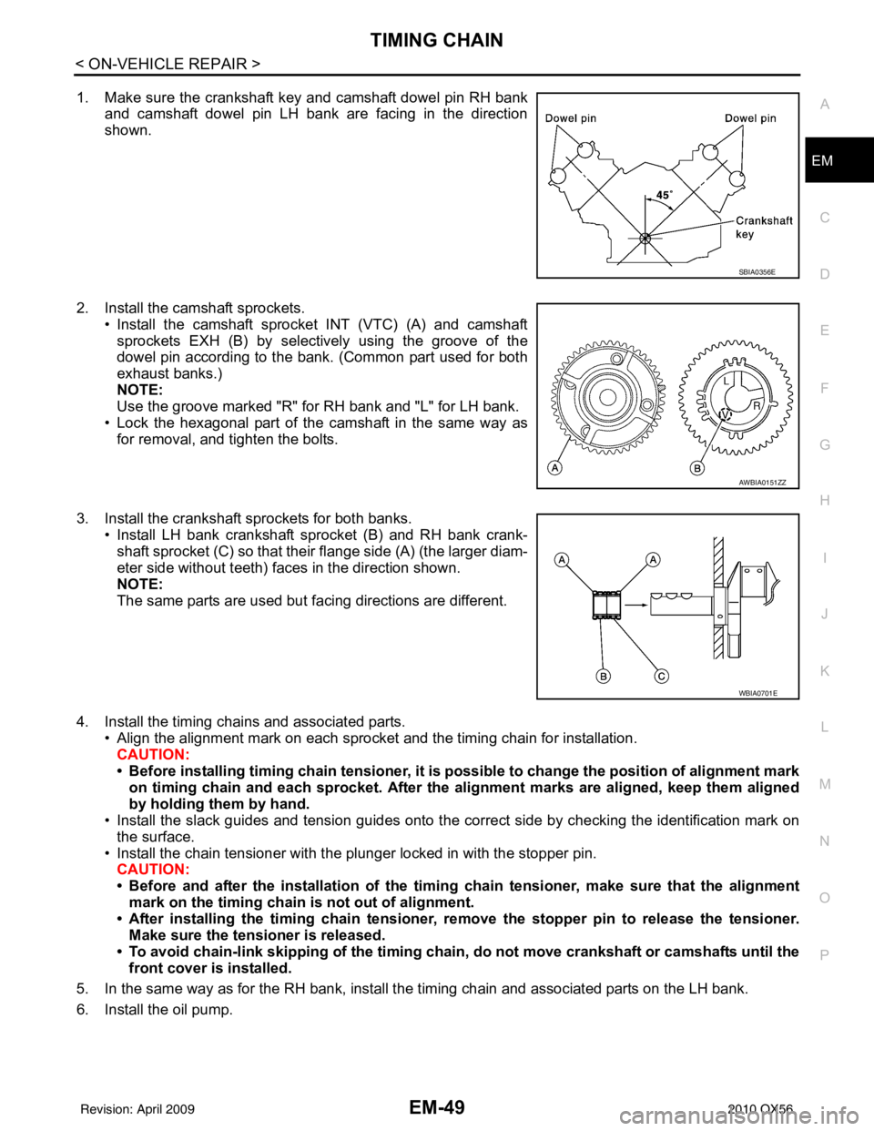
1. Make sure the crankshaft key and camshaft dowel pin RH bank
and camshaft dowel pin LH bank are facing in the direction
shown.
2. Install the camshaft sprockets. • Install the camshaft sprocket INT (VTC) (A) and camshaftsprockets EXH (B) by selectively using the groove of the
dowel pin according to the bank. (Common part used for both
exhaust banks.)
NOTE:
Use the groove marked "R" for RH bank and "L" for LH bank.
• Lock the hexagonal part of the camshaft in the same way as for removal, and tighten the bolts.
3. Install the crankshaft sprockets for both banks. • Install LH bank crankshaft sprocket (B) and RH bank crank-shaft sprocket (C) so that their flange side (A) (the larger diam-
eter side without teeth) faces in the direction shown.
NOTE:
The same parts are used but facing directions are different.
4. Install the timing chains and associated parts. • Align the alignment mark on each sprocket and the timing chain for installation.CAUTION:
• Before installing timing chain tensioner, it is possible to change the position of alignment mark
on timing chain and each sprocket . After the alignment marks are aligned, keep them aligned
by holding them by hand.
• Install the slack guides and tension guides onto the correct side by checking the identification mark on
the surface.
• Install the chain tensioner with t he plunger locked in with the stopper pin.
CAUTION:
• Before and after the installation of the timing chain tensioner, make sure that the alignment
mark on the timing chain is not out of alignment.
• After installing the timing chain tensioner, remove the stopp er pin to release the tensioner.
Make sure the tensioner is released.
• To avoid chain-link skipping of the timing chain, do not move crankshaft or camshafts until the
front cover is installed.
5. In the same way as for the RH bank, install the timing chain and associated parts on the LH bank.
6. Install the oil pump.
SBIA0356E
AWBIA0151ZZ
WBIA0701E
Revision: April 20092010 QX56
Page 1914 of 4210
CAMSHAFTEM-63
< ON-VEHICLE REPAIR >
C
DE
F
G H
I
J
K L
M A
EM
NP
O
• Perform this inspection only when
DTC P0011 is detected in self-diagnostic results of CONSULT III
and it is directed according to inspecti on procedure of EC section. Refer to EC-88, "
On Board Diag-
nosis Logic".
1. Check engine oil level. Refer to LU-8, "
Inspection".
2. Perform the following procedure so as to prevent the engine from being unintentionally started while checking.
a. Release fuel pressure. Refer to EC-489, "
Fuel Pressure Check".
b. Disconnect ignition coil and injector harness connectors if practical.
3. Remove IVT control solenoid valve.
4. Crank engine, and then make sure that engine oil comes out from IVT control cover oil hole. End cranking after checking.
WARNING:
Be careful not to touch rotating parts (drive be lts, idler pulley, and crankshaft pulley, etc.).
CAUTION:
• Engine oil may squirt from IVT control solenoid valve installation hole during cranking. Use a
shop cloth to prevent engine oil from splash ing on worker, engine components and vehicle.
• Do not allow engine oil to get on rubber components such as drive belts or engine mount insula- tors. Immediately wipe off any splashed engine oil.
5. Clean oil groove between oil strainer and IVT control solenoid valve if engine oil does not come out from IVT control valve cover oil hole. Refer to LU-7, "
Schematic".
6. Remove components between IVT control solenoid valve and camshaft sprocket (INT), and then check each oil groove for clogging.
• Clean oil groove if necessary.
7. After inspection, installation of the remaining components is in the reverse order of removal.
Revision: April 20092010 QX56
Page 2224 of 4210
GI-1
GENERAL INFORMATION
C
DE
F
G H
I
J
K L
M B
GI
SECTION GI
N
O P
CONTENTS
GENERAL INFORMATION
HOW TO USE THIS MANU AL ......................3
HOW TO USE THIS MANUAL ....................... .....3
Description .......................................................... ......3
Terms ........................................................................3
Units ..........................................................................3
Contents ....................................................................3
Relation between Illustrations and Descriptions .......4
Components ..............................................................4
HOW TO FOLLOW TROUBLE DIAGNOSES .....6
Description ................................................................6
How to Follow Test Groups in Trouble Diagnosis ......6
Key to Symbols Signifying Measurements or Pro-
cedures ............................................................... ......
7
HOW TO READ WIRING DIAGRAMS ................9
Connector symbols ............................................. ......9
Sample/wiring diagram -example- ...........................10
Description ..............................................................11
ABBREVIATIONS .......................................... ....13
Abbreviation List .................................................. ....13
TIGHTENING TORQUE OF STANDARD
BOLTS ................................................................
14
Tightening Torque Table .........................................14
RECOMMENDED CHEMICAL PRODUCTS
AND SEALANTS ............................................ ....
15
Recommended Chemical Products and Sealants ....15
TERMINOLOGY .................................................16
SAE J1930 Terminology List ............................... ....16
FEATURES OF NEW MODEL .....................20
IDENTIFICATION INFORMATION .....................20
Model Variation ................................................... ....20
Identification Number ..............................................21
Identification Plate ...................................................22
Dimensions .............................................................23
Wheels & Tires .................................................... ....23
PRECAUTION ..............................................24
PRECAUTIONS .................................................24
Description ........................................................... ....24
Precaution for Supplemental Restraint System
(SRS) "AIR BAG" and "SEAT BELT PRE-TEN-
SIONER" .................................................................
24
Precaution Necessary for Steering Wheel Rota-
tion After Battery Disconnect ...................................
24
Procedures without Cowl Top Cover .......................25
General Precautions ................................................25
Three Way Catalyst .................................................27
Precaution for Fuel (Unleaded Premium Gasoline
Required) .................................................................
27
Multiport Fuel Injection System or Engine Control
System .....................................................................
27
Hoses ......................................................................27
Engine Oils ..............................................................28
Air Conditioning .......................................................29
LIFTING POINT .................................................30
Pantograph Jack ......................................................30
Garage Jack and Safety Stand ................................30
2-Pole Lift ................................................................30
TOW TRUCK TOWING .....................................32
Tow Truck Towing ...................................................32
Vehicle Recovery (Freeing a stuck vehicle) ............33
BASIC INSPECTION ...................................34
SERVICE INFORMATION FOR ELECTRICAL
INCIDENT ..........................................................
34
Work Flow ............................................................ ....34
Control Units and Electrical Parts ............................34
How to Check Terminal ...........................................35
Intermittent Incident ............................................. ....38
Circuit Inspection .....................................................41
CONSULT-III CHECKING SYSTEM .................46
Revision: April 20092010 QX56
Page 2258 of 4210
SERVICE INFORMATION FOR ELECTRICAL INCIDENTGI-35
< BASIC INSPECTION >
C
DE
F
G H
I
J
K L
M B
GI
N
O P
• Do not apply excessive shock to the control unit by dropping or hit- ting it.
• Be careful to prevent condensation in the control unit due to rapid
temperature changes and do not let water or rain get on it. If water
is found in the control unit, dry it fully and then install it in the vehi-
cle.
• Be careful not to let oil to get on the control unit connector.
• Avoid cleaning the control unit with volatile oil.
• Do not disassemble the control unit, and do not remove the upper and lower covers.
• When using a DMM, be careful not to let test probes get close to each other to prevent the power transistor in the control unit from
damaging battery voltage because of short circuiting.
• When checking input and output signals of the control unit, use the specified check adapter.
How to Check TerminalINFOID:0000000005149606
CONNECTOR AND TERMINAL PIN KIT
• Use the connector and terminal pin kits listed below when replacing connectors or terminals.
• The connector and terminal pin kits contain some of the most commonly used NISSAN/INFINITI connectors
and terminals. For detailed connector and terminal pin r eplacement procedures, refer to the latest NISSAN/
INFINITI CONNECTOR AND TERMINAL PIN SERVICE MANUAL.
SAIA0255E
SEF348N
Revision: April 20092010 QX56