2010 INFINITI QX56 automatic transmission
[x] Cancel search: automatic transmissionPage 3743 of 4210

TM-48
< COMPONENT DIAGNOSIS >
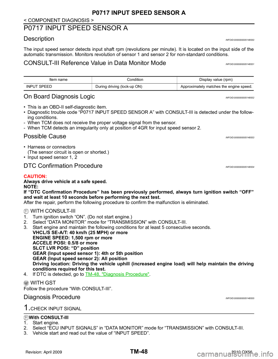
P0717 INPUT SPEED SENSOR A
P0717 INPUT SPEED SENSOR A
DescriptionINFOID:0000000005148550
The input speed sensor detects input shaft rpm (revolutions per minute). It is located on the input side of the
automatic transmission. Monitors revolution of sensor 1 and sensor 2 for non-standard conditions.
CONSULT-III Reference Value in Data Monitor ModeINFOID:0000000005148551
On Board Diagnosis LogicINFOID:0000000005148552
• This is an OBD-II self-diagnostic item.
• Diagnostic trouble code “P0717 INPUT SPEED SENSOR A” with CONSULT-III is detected under the follow-
ing conditions.
- When TCM does not receive the proper voltage signal from the sensor.
- When TCM detects an irregularity only at pos ition of 4GR for input speed sensor 2.
Possible CauseINFOID:0000000005148553
• Harness or connectors
(The sensor circuit is open or shorted.)
• Input speed sensor 1, 2
DTC Confirmation ProcedureINFOID:0000000005148554
CAUTION:
Always drive vehicle at a safe speed.
NOTE:
If “DTC Confirmation Procedure” has been previously performed, always turn ignition switch “OFF”
and wait at least 10 seconds before performing the next test.
After the repair, perform the following proc edure to confirm the malfunction is eliminated.
WITH CONSULT-III
1. Turn ignition switch “ON”. (Do not start engine.)
2. Select “DATA MONITOR” mode for “TRANSMISSION” with CONSULT-III.
3. Start engine and maintain the following conditions for at least 5 consecutive seconds.
VHCL/S SE-A/T: 40 km/h (25 MPH) or more
ENGINE SPEED: 1,500 rpm or more
ACCELE POSI: 0.5/8 or more
SLCT LVR POSI: “D” position
GEAR (Input speed sensor 1): 4th or 5th position
GEAR (Input speed sensor 2): All position
Driving location: Driving the vehicle uphill (increased engine load) will help maintain the driving
conditions required for this test.
4. If DTC is detected, go to TM-48, "
Diagnosis Procedure".
WITH GST
Follow the procedure “With CONSULT-III”.
Diagnosis ProcedureINFOID:0000000005148555
1.CHECK INPUT SIGNAL
With CONSULT-III
1. Start engine.
2. Select “ECU INPUT SIGNALS” in “DATA MONI TOR” mode for “TRANSMISSION” with CONSULT-III.
3. Vehicle start and read out the value of “INPUT SPEED”.
Item name Condition Display value (rpm)
INPUT SPEED During driving (lock-up ON) Approximately matches the engine speed.
Revision: April 20092010 QX56
Page 3839 of 4210

TM-144
< PRECAUTION >
PRECAUTIONS
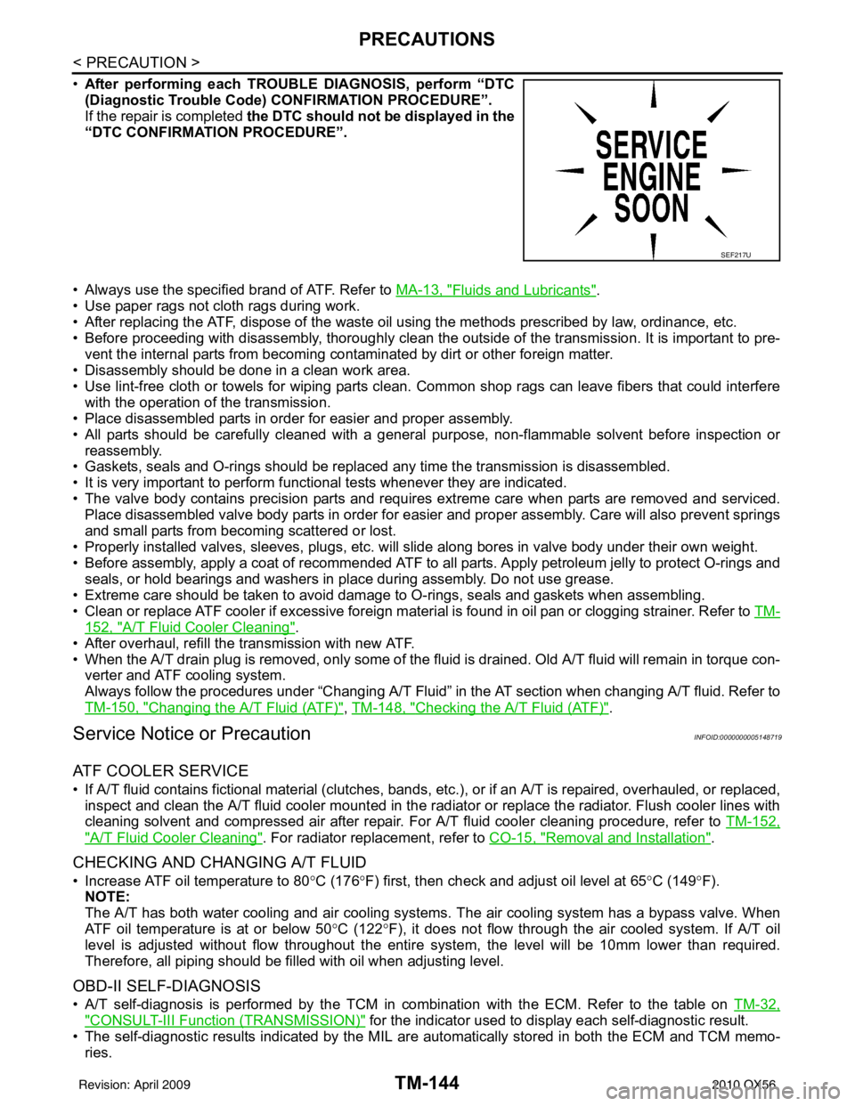
•After performing each TROUBLE DIAGNOSIS, perform “DTC
(Diagnostic Trouble Code) CONFIRMATION PROCEDURE”.
If the repair is completed the DTC should not be displayed in the
“DTC CONFIRMATION PROCEDURE”.
• Always use the specified brand of ATF. Refer to MA-13, "
Fluids and Lubricants".
• Use paper rags not cloth rags during work.
• After replacing the ATF, dispose of the waste oil using the methods prescribed by law, ordinance, etc.
• Before proceeding with disassembly, thoroughly clean the outside of the transmission. It is important to pre- vent the internal parts from becoming cont aminated by dirt or other foreign matter.
• Disassembly should be done in a clean work area.
• Use lint-free cloth or towels for wiping parts clean. Common shop rags can leave fibers that could interfere
with the operation of the transmission.
• Place disassembled parts in order for easier and proper assembly.
• All parts should be carefully cleaned with a general purpose, non-flammable solvent before inspection or
reassembly.
• Gaskets, seals and O-rings should be replaced any time the transmission is disassembled.
• It is very important to perform functional tests whenever they are indicated.
• The valve body contains precision parts and requires extreme care when parts are removed and serviced. Place disassembled valve body parts in order for easier and proper assembly. Care will also prevent springs
and small parts from becoming scattered or lost.
• Properly installed valves, sleeves, plugs, etc. will slide along bores in valve body under their own weight.
• Before assembly, apply a coat of recommended ATF to all parts. Apply petroleum jelly to protect O-rings and
seals, or hold bearings and washers in place during assembly. Do not use grease.
• Extreme care should be taken to avoid damage to O-rings, seals and gaskets when assembling.
• Clean or replace ATF cooler if excessive foreign material is found in oil pan or clogging strainer. Refer to TM-
152, "A/T Fluid Cooler Cleaning".
• After overhaul, refill the transmission with new ATF.
• When the A/T drain plug is removed, only some of the fluid is drained. Old A/T fluid will remain in torque con- verter and ATF cooling system.
Always follow the procedures under “Changing A/T Fluid” in the AT section when changing A/T fluid. Refer to
TM-150, "
Changing the A/T Fluid (ATF)", TM-148, "Checking the A/T Fluid (ATF)".
Service Notice or PrecautionINFOID:0000000005148719
ATF COOLER SERVICE
• If A/T fluid contains fictional material (clutches, bands, etc.), or if an A/T is repaired, overhauled, or replaced,
inspect and clean the A/T fluid cooler mounted in the radiator or replace the radiator. Flush cooler lines with
cleaning solvent and compressed air after repair. For A/T fluid cooler cleaning procedure, refer to TM-152,
"A/T Fluid Cooler Cleaning". For radiator replacement, refer to CO-15, "Removal and Installation".
CHECKING AND CHANGING A/T FLUID
• Increase ATF oil temperature to 80 °C (176° F) first, then check and adjust oil level at 65 °C (149° F).
NOTE:
The A/T has both water cooling and air cooling systems . The air cooling system has a bypass valve. When
ATF oil temperature is at or below 50 °C (122° F), it does not flow through the air cooled system. If A/T oil
level is adjusted without flow throughout the entire system, the level will be 10mm lower than required.
Therefore, all piping should be filled with oil when adjusting level.
OBD-II SELF-DIAGNOSIS
• A/T self-diagnosis is performed by the TCM in combination with the ECM. Refer to the table on TM-32,
"CONSULT-III Function (TRANSMISSION)" for the indicator used to display each self-diagnostic result.
• The self-diagnostic results indicated by the MIL ar e automatically stored in both the ECM and TCM memo-
ries.
SEF217U
Revision: April 20092010 QX56
Page 3960 of 4210

SERVICE DATA AND SPECIFICATIONS (SDS)TM-265
< SERVICE DATA AND SPECIFICATIONS (SDS)
CEF
G H
I
J
K L
M A
B
TM
N
O P
SERVICE DATA AND SPECIFICATIONS (SDS)
SERVICE DATA AND SPECIFICATIONS (SDS)
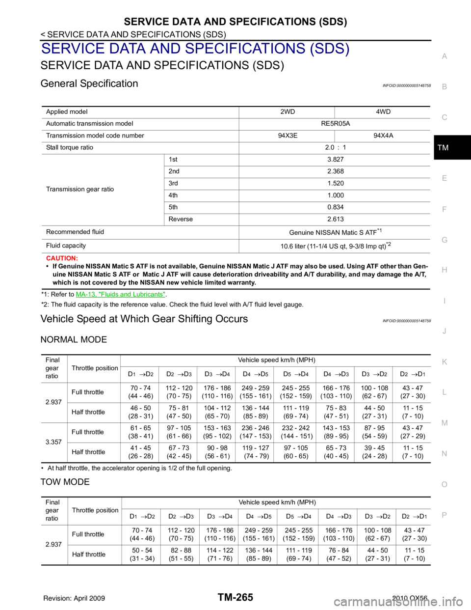
General SpecificationINFOID:0000000005148758
*1: Refer to MA-13, "Fluids and Lubricants".
*2: The fluid capacity is the reference value. Check the fluid level with A/T fluid level gauge.
Vehicle Speed at Which Gear Shifting OccursINFOID:0000000005148759
NORMAL MODE
• At half throttle, the accelerator opening is 1/2 of the full opening.
TOW MODE
Applied model 2WD4WD
Automatic transmission model RE5R05A
Transmission model code number 94X3E94X4A
Stall torque ratio 2.0 : 1
Transmission gear ratio 1st
3.827
2nd 2.368
3rd 1.520
4th 1.000
5th 0.834
Reverse 2.613
Recommended fluid Genuine NISSAN Matic S ATF
*1
Fluid capacity10.6 liter (11-1/4 US qt, 9-3/8 Imp qt)*2
CAUTION:
• If Genuine NISSAN Matic S ATF is not available, Genuine NISSAN Matic J ATF may also be used. Using ATF other than Gen-
uine NISSAN Matic S ATF or Matic J ATF will cause deterioration driveability and A/T durability, and may damage the A/T,
which is not covered by the NISSAN new vehicle limited warranty.
Final
gear
ratio Throttle position
Vehicle speed km/h (MPH)
D
1 → D2D2 →D3D3 →D4D4 →D5D5 →D4D4 →D3D3 → D2D2 →D1
2.937 Full throttle
70 - 74
(44 - 46) 112 - 120
(70 - 75) 176 - 186
(110 - 116) 249 - 259
(155 - 161) 245 - 255
(152 - 159) 166 - 176
(103 - 110) 100 - 108
(62 - 67) 43 - 47
(27 - 30)
Half throttle 46 - 50
(28 - 31) 75 - 81
(47 - 50) 104 - 112
(65 - 70) 136 - 144
(85 - 89) 111 - 11 9
(69 - 74) 75 - 83
(47 - 51) 44 - 50
(27 - 31) 11 - 1 5
(7 - 10)
3.357 Full throttle
61 - 65
(38 - 41) 97 - 105
(61 - 66) 153 - 163
(95 - 102) 236 - 246
(147 - 153) 232 - 242
(144 - 151) 143 - 153
(89 - 95) 87 - 95
(54 - 59) 43 - 47
(27 - 29)
Half throttle 41 - 45
(26 - 28) 67 - 73
(42 - 45) 90 - 98
(56 - 61) 11 9 - 1 2 7
(74 - 79) 97 - 105
(60 - 65) 65 - 73
(40 - 45) 39 - 45
(24 - 28) 11 - 1 5
(7 - 10)
Final
gear
ratio Throttle position Vehicle speed km/h (MPH)
D
1 → D2D2 →D3D3 →D4D4 →D5D5 →D4D4 →D3D3 → D2D2 →D1
2.937 Full throttle
70 - 74
(44 - 46) 112 - 120
(70 - 75) 176 - 186
(110 - 116) 249 - 259
(155 - 161) 245 - 255
(152 - 159) 166 - 176
(103 - 110) 100 - 108
(62 - 67) 43 - 47
(27 - 30)
Half throttle 50 - 54
(31 - 34) 82 - 88
(51 - 55) 114 - 122
(71 - 76) 136 - 144
(85 - 89) 111 - 11 9
(69 - 74) 76 - 84
(47 - 52) 44 - 50
(27 - 31) 11 - 1 5
(7 - 10)
Revision: April 20092010 QX56