Page 4108 of 4210

LOW TIRE PRESSURE WARNING LAMP BLINKSWT-39
< SYMPTOM DIAGNOSIS >
C
DF
G H
I
J
K L
M A
B
WT
N
O P
LOW TIRE PRESSURE WA RNING LAMP BLINKS
Low Tire Pressure Warning Lamp Flas hes When Ignition Switch Is Turned On
INFOID:0000000005148237
Regarding Wiring Diagram information, refer to WT-30, "Wiring Diagram - TIRE PRESSURE MONITORING
SYSTEM -".
NOTE:
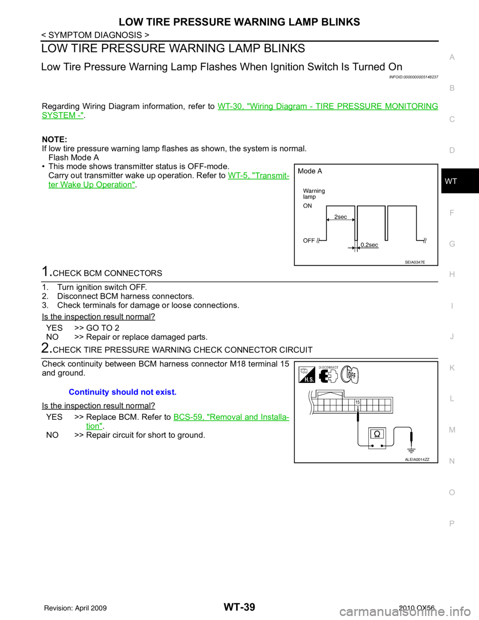
If low tire pressure warning lamp fl ashes as shown, the system is normal.
Flash Mode A
• This mode shows transmitter status is OFF-mode.
Carry out transmitter wake up operation. Refer to WT-5, "
Transmit-
ter Wake Up Operation".
1.CHECK BCM CONNECTORS
1. Turn ignition switch OFF.
2. Disconnect BCM harness connectors.
3. Check terminals for damage or loose connections.
Is the inspection result normal?
YES >> GO TO 2
NO >> Repair or replace damaged parts.
2.CHECK TIRE PRESSURE WARNING CHECK CONNECTOR CIRCUIT
Check continuity between BCM harness connector M18 terminal 15
and ground.
Is the inspection result normal?
YES >> Replace BCM. Refer to BCS-59, "Removal and Installa-
tion".
NO >> Repair circuit for short to ground.
SEIA0347E
Continuity should not exist.
ALEIA0014ZZ
Revision: April 20092010 QX56
Page 4109 of 4210
WT-40
< SYMPTOM DIAGNOSIS >
HAZARD WARNING LAMPS FLASH
HAZARD WARNING LAMPS FLASH
Hazard Warning Lamps Flash When Ignition Switch Is Turned OnINFOID:0000000005148238
DIAGNOSTIC PROCEDURE
1.CHECK BCM GROUND CIRCUIT
Check BCM ground circuit. Refer to BCS-33, "
Diagnosis Procedure".
Is the inspection result normal?
YES >> Replace BCM. Refer to BCS-59, "Removal and Installation".
NO >> Repair BCM ground circuit.
Revision: April 20092010 QX56
Page 4110 of 4210
"TIRE PRESSURE" INFORMATION IN DISPLAY UNIT DOES NOT EXIST
WT-41
< SYMPTOM DIAGNOSIS >
C
D F
G H
I
J
K L
M A
B
WT
N
O P
"TIRE PRESSURE" INFORMATION IN DISPLAY UNIT DOES NOT EXIST
"TIRE PRESSURE" Information in Display Unit Does Not ExistINFOID:0000000005148239
DIAGNOSTIC PROCEDURE
1.SELF-DIAGNOSTIC RESULT CHECK
Using CONSULT-III, check display contents in self-diagnostic results.
Is "CAN COMM CIRCUIT" displayed in the self-diagnosis display items?
YES >> Malfunction in CAN communication system.
NO >> GO TO 2.
2.CHECK DISPLAY UNIT
Perform display unit self-diagnosis. Refer to AV-38, "
AV CONTROL UNIT : CONSULT-III Function".
Is the inspection result normal?
YES >> Replace BCM. Refer to BCS-59, "Removal and Installation".
NO >> Repair or replace malfunctioning parts.
Revision: April 20092010 QX56
Page 4112 of 4210

NOISE, VIBRATION AND HARSHNESS (NVH) TROUBLESHOOTINGWT-43
< SYMPTOM DIAGNOSIS >
C
DF
G H
I
J
K L
M A
B
WT
N
O P
NOISE, VIBRATION AND HARSHN ESS (NVH) TROUBLESHOOTING
NVH Troubleshooting ChartINFOID:0000000005148241
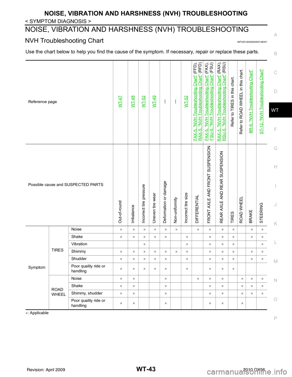
Use the chart below to help you find t he cause of the symptom. If necessary, repair or replace these parts.
×: ApplicableReference page
WT-47WT-48WT-52WT-49—
—
WT-52
FA X - 5 , "
NVH Troubleshooting Chart
" (FFD),
RAX-5, "
NVH Troubleshooting Chart
" (RFD)
FA X - 5 , "
NVH Troubleshooting Chart
" (FAX),
FSU-5, "
NVH Troubleshooting Chart
" (FSU)
RAX-5, "
NVH Troubleshooting Chart
" (RAX),
RSU-5, "
NVH Troubleshooting Chart
" (RSU)
Refer to TIRES in this chart.
Refer to ROAD WHEEL in this chart.
BR-6, "
NVH Troubleshooting Chart
"
ST-12, "
NVH Troubleshooting Chart
"
Possible cause and SUSPECTED PARTS
Out-of-round
Imbalance
Incorrect tire pressure
Uneven tire wear
Deformation or damage
Non-uniformity
Incorrect tire size
DIFFERENTIAL
FRONT AXLE AND FRONT SUSPENSION
REAR AXLE AND REAR SUSPENSION
TIRES
ROAD WHEEL
BRAKE
STEERING
Symptom TIRESNoise
× ××××× × × ×× ××
Shake × ×××× × × ×× ××
Vibration ××× ×××
Shimmy × ×××××× × ×× ××
Shudder × ×××× × × ×× ××
Poor quality ride or
handling × ×××× × × ××
ROAD
WHEEL Noise
×× × ××× ×××
Shake ×× × ×× ×××
Shimmy, shudder ×× × ×× ×××
Poor quality ride or
handling ×× ×
×× ×
Revision: April 20092010 QX56
Page 4113 of 4210

WT-44
< PRECAUTION >
PRECAUTIONS
PRECAUTION
PRECAUTIONS
Precaution for Supplemental Restraint System (SRS) "AIR BAG" and "SEAT BELT
PRE-TENSIONER"
INFOID:0000000005229917
The Supplemental Restraint System such as “A IR BAG” and “SEAT BELT PRE-TENSIONER”, used along
with a front seat belt, helps to reduce the risk or severity of injury to the driver and front passenger for certain
types of collision. This system includes seat belt switch inputs and dual stage front air bag modules. The SRS
system uses the seat belt switches to determine the front air bag deployment, and may only deploy one front
air bag, depending on the severity of a collision and w hether the front occupants are belted or unbelted.
Information necessary to service the system safely is included in the SR and SB section of this Service Man-
ual.
WARNING:
• To avoid rendering the SRS inopera tive, which could increase the risk of personal injury or death in
the event of a collision which would result in air bag inflation, all maintenance must be performed by
an authorized NISSAN/INFINITI dealer.
• Improper maintenance, including in correct removal and installation of the SRS, can lead to personal
injury caused by unintent ional activation of the system. For re moval of Spiral Cable and Air Bag
Module, see the SR section.
• Do not use electrical test equipmen t on any circuit related to the SRS unless instructed to in this
Service Manual. SRS wiring harn esses can be identified by yellow and/or orange harnesses or har-
ness connectors.
PRECAUTIONS WHEN USING POWER TOOLS (AIR OR ELECTRIC) AND HAMMERS
WARNING:
• When working near the Airbag Diagnosis Sensor Unit or other Airbag System sensors with the Igni-
tion ON or engine running, DO NOT use air or electri c power tools or strike near the sensor(s) with a
hammer. Heavy vibration could activate the sensor( s) and deploy the air bag(s), possibly causing
serious injury.
• When using air or electric power tools or hammers , always switch the Ignition OFF, disconnect the
battery, and wait at least 3 minu tes before performing any service.
Precaution Necessary for Steering W heel Rotation After Battery Disconnect
INFOID:0000000005229918
NOTE:
• This Procedure is applied only to models with Intelligent Key system and NATS (NISSAN ANTI-THEFT SYS-
TEM).
• Remove and install all control units after disconnecting both battery cables with the ignition knob in the
″LOCK ″ position.
• Always use CONSULT-III to perform self-diagnosis as a part of each function inspection after finishing work.
If DTC is detected, perform trouble diagnosis according to self-diagnostic results.
For models equipped with the Intelligent Key system and NATS, an electrically controlled steering lock mech-
anism is adopted on the key cylinder.
For this reason, if the battery is disconnected or if the battery is discharged, the steering wheel will lock and
steering wheel rotation will become impossible.
If steering wheel rotation is required when battery pow er is interrupted, follow the procedure below before
starting the repair operation.
OPERATION PROCEDURE
1. Connect both battery cables. NOTE:
Supply power using jumper cables if battery is discharged.
2. Use the Intelligent Key or mechanical key to turn the ignition switch to the ″ACC ″ position. At this time, the
steering lock will be released.
3. Disconnect both battery cables. The steering lock will remain released and the steering wheel can be rotated.
4. Perform the necessary repair operation.
Revision: April 20092010 QX56
Page 4114 of 4210
PRECAUTIONSWT-45
< PRECAUTION >
C
DF
G H
I
J
K L
M A
B
WT
N
O P
5. When the repair work is completed, return the ignition switch to the ″LOCK ″ position before connecting
the battery cables. (At this time, the steering lock mechanism will engage.)
6. Perform a self-diagnosis check of al l control units using CONSULT-III.
Revision: April 20092010 QX56
Page 4117 of 4210

WT-48
< ON-VEHICLE REPAIR >
WHEEL AND TIRE ASSEMBLY
ON-VEHICLE REPAIR
WHEEL AND TIRE ASSEMBLY
Balancing WheelsINFOID:0000000005148246
Removal
1. Using releasing agent, remove double-faced adhesive tape from the wheel.CAUTION:
• Be careful not to scratch the wheel during removal.
• After removing double-faced adh esive tape, wipe clean traces of releasing agent from the wheel.
Wheel Balance Adjustment
• If a tire balance machine has adhesion balance weight mode settings and drive-in weight mode setting,
select and adjust a drive-in weight mode suitable for wheels.
1. Set wheel on wheel balancer using the center hole as a guide. Start the tire balance machine.
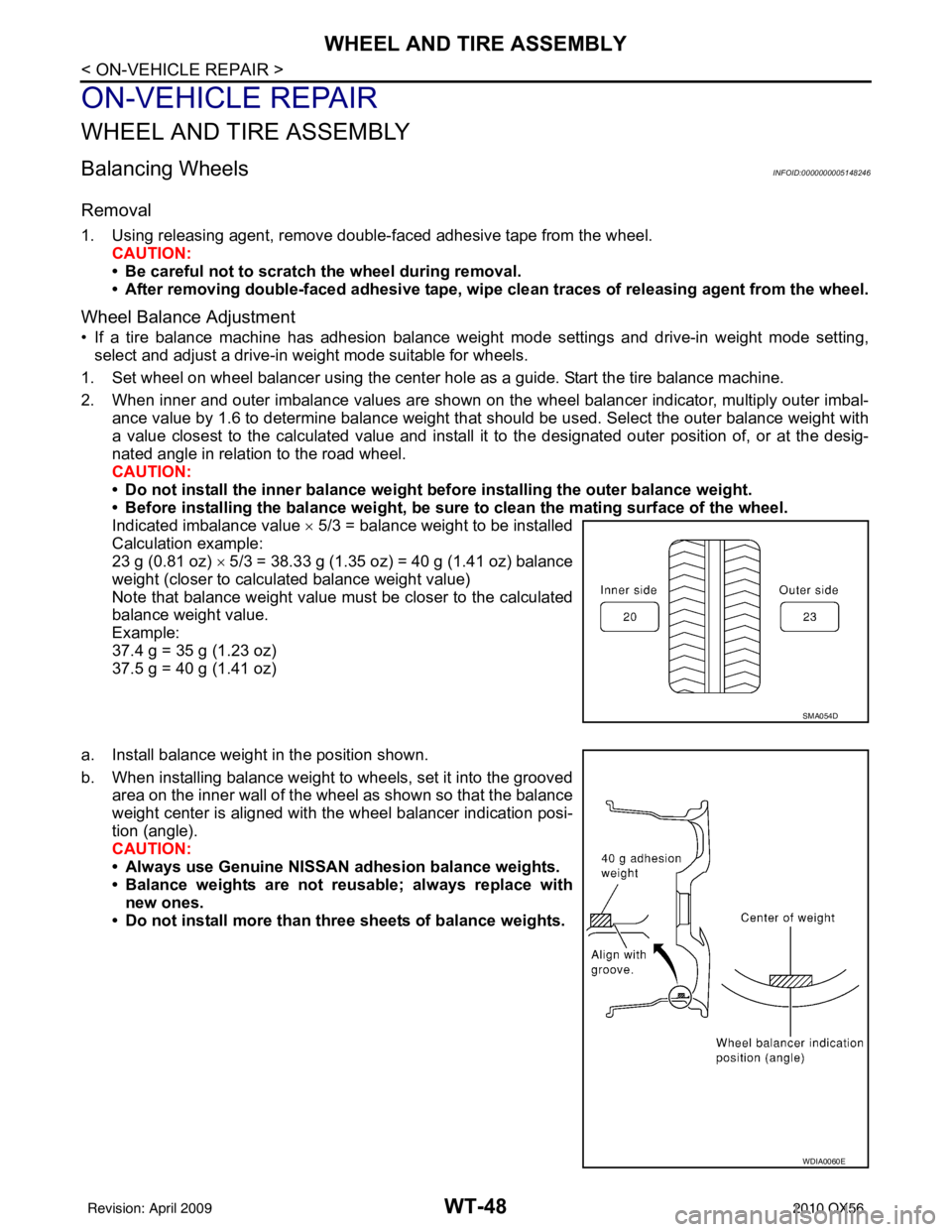
2. When inner and outer imbalance values are shown on the wheel balancer indicator, multiply outer imbal- ance value by 1.6 to determine balance weight that should be used. Select the outer balance weight with
a value closest to the calculated value and install it to the designated outer posit ion of, or at the desig-
nated angle in relation to the road wheel.
CAUTION:
• Do not install the inner balance weight before installing the outer balance weight.
• Before installing the balance weight, be sure to clean the mating surface of the wheel.
Indicated imbalance value × 5/3 = balance weight to be installed
Calculation example:
23 g (0.81 oz) × 5/3 = 38.33 g (1.35 oz) = 40 g (1.41 oz) balance
weight (closer to calculated balance weight value)
Note that balance weight value must be closer to the calculated
balance weight value.
Example:
37.4 g = 35 g (1.23 oz)
37.5 g = 40 g (1.41 oz)
a. Install balance weight in the position shown.
b. When installing balance weight to wheels, set it into the grooved area on the inner wall of the wheel as shown so that the balance
weight center is aligned with the wheel balancer indication posi-
tion (angle).
CAUTION:
• Always use Genuine NISSAN ad hesion balance weights.
• Balance weights are not reusable; always replace with new ones.
• Do not install more than three sheets of balance weights.
SMA054D
WDIA0060E
Revision: April 20092010 QX56
Page 4118 of 4210

WHEEL AND TIRE ASSEMBLYWT-49
< ON-VEHICLE REPAIR >
C
DF
G H
I
J
K L
M A
B
WT
N
O P
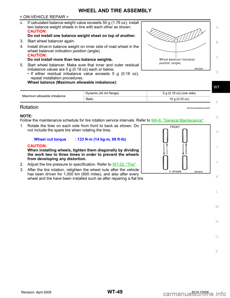
c. If calculated balance weight value exceeds 50 g (1.76 oz), install two balance weight sheets in line with each other as shown.
CAUTION:
Do not install one balance weig ht sheet on top of another.
3. Start wheel balancer again.
4. Install drive-in balance weight on inner side of road wheel in the wheel balancer indication position (angle).
CAUTION:
Do not install more than two balance weights.
5. Start wheel balancer. Make sure that inner and outer residual imbalance values are 5 g (0.18 oz) each or below.
• If either residual imbalance value exceeds 5 g (0.18 oz),repeat installation procedures.
Wheel balance (Maximum allowable imbalance):
RotationINFOID:0000000005148247
NOTE:
Follow the maintenance schedule for tire rotation service intervals. Refer to MA-6, "
General Maintenance" .
1. Rotate the tires on each side from front to back as shown. Do not include the spare tire when rotating the tires.
CAUTION:
When installing wheel s, tighten them diagonally by dividing
the work two to three times in order to prevent the wheels
from developing any distortion.
2. Adjust the tire pressure to specification. Refer to WT-52, "
Tire" .
3. After the tire rotation, retighten the wheel nuts after the vehicle has been driven for 1,000 km (600 miles), and also after every
wheel and tire have been installed such as after repairing a flat tire.
Maximum allowable imbalance Dynamic (At rim flange) 5 g (0.18 oz) (one side)
Static
10 g (0.35 oz)
SMA056D
Wheel nut torque : 133 N·m (14 kg-m, 98 ft-lb)
SMA829C
Revision: April 20092010 QX56