Page 3956 of 4210
![INFINITI QX56 2010 Factory Service Manual ASSEMBLYTM-261
< DISASSEMBLY AND ASSEMBLY >
CEF
G H
I
J
K L
M A
B
TM
N
O P
iii. Install plug (1) [with bracket (2)] to control valve with TCM and tighten bolt ( ) to specified torque.
CAUTION:
Adjust INFINITI QX56 2010 Factory Service Manual ASSEMBLYTM-261
< DISASSEMBLY AND ASSEMBLY >
CEF
G H
I
J
K L
M A
B
TM
N
O P
iii. Install plug (1) [with bracket (2)] to control valve with TCM and tighten bolt ( ) to specified torque.
CAUTION:
Adjust](/manual-img/42/57032/w960_57032-3955.png)
ASSEMBLYTM-261
< DISASSEMBLY AND ASSEMBLY >
CEF
G H
I
J
K L
M A
B
TM
N
O P
iii. Install plug (1) [with bracket (2)] to control valve with TCM and tighten bolt ( ) to specified torque.
CAUTION:
Adjust bolt hole of bracket to bolt hole of control valve.
14. Install control valve with TCM in transmission case. CAUTION:
• Make sure that input speed sensor is securely installed
into input speed sensor hole (A).
• Hang down output speed sensor harness toward outside so as not to disturb installati on of control valve with TCM.
• Adjust A/T assembly harness connector of control valve
with TCM to terminal hole of transmission case.
• Assemble it so that manual valve cutout is engaged with
manual plate projection.
15. Install bolts (A), (B) and (C) to control valve with TCM.
16. Tighten bolt (A), (B) and (C) temporarily to prevent dislocation. After that tighten them in order (A → B → C), and then tighten
other bolts. Bracket bolt : 7.9 N·m (0.81 kg-m, 70 in-lb)
JSDIA1311ZZ
1 : Brake band
JSDIA1318ZZ
SCIA5035E
: Front
Bolt symbol Length mm (in) Number of bolts
A 42 (1.65) 5
B 55 (2.17) 6
C 40 (1.57) 1
SCIA8077E
: Front
Bolt symbol A B C
Number of bolts 5 6 1
Length mm (in) 42 (1.65) 55 (2.17) 40 (1.57)
SCIA8078E
Revision: April 20092010 QX56
Page 3957 of 4210
TM-262
< DISASSEMBLY AND ASSEMBLY >
ASSEMBLY
17. After installing the A/T fluid temperature sensor 2, connect the A/T fluid temperature sensor 2 connector
as shown below.
a. Connect A/T fluid temperature sensor 2 connector (A).
b. Securely fasten terminal cord assembly and A/T fluid tempera- ture sensor 2 harness with terminal clips.
18. Connect output speed sensor connector (1).
19. Securely fasten output speed sensor harness with terminal clip ().
20. Pull down A/T assembly harness connector. CAUTION:
Do not damage connector.
Tightening torque
N·m (km-g, in-lb) 7.9 (0.81, 70)With ATF applied
7.9 (0.81, 70)
SCIA8124E
JSDIA1319ZZ
JSDIA1320ZZ
SCIA5299E
Revision: April 20092010 QX56
Page 3958 of 4210
ASSEMBLYTM-263
< DISASSEMBLY AND ASSEMBLY >
CEF
G H
I
J
K L
M A
B
TM
N
O P
21. Install snap ring to A/T assembly harness connector.
22. Install magnets in oil pan.
23. Install oil pan to transmission case. Refer to TM-170, "
Oil Pan".
24. Install torque converter.
a. Pour ATF into torque converter. NOTE:
• Approximately 2 liters (2-1/8 US qt. 1-3/4 Imp qt) of fluid is
required for a new torque converter.
• When reusing old torque converter, add the same amount of
fluid as was drained.
b. Install torque converter while aligning notches of torque con- verter with notches of oil pump.
CAUTION:
Install torque converte r while rotating it.
SCIA5300E
SCIA5200E
SAT428DA
SCIA5010E
Revision: April 20092010 QX56
Page 3959 of 4210
TM-264
< DISASSEMBLY AND ASSEMBLY >
ASSEMBLY
c. Measure distance "A" to make sure that torque converter is inproper position.
Distance "A" : 24.0 mm (0.94 in)
SCIA5694E
Revision: April 20092010 QX56
Page 3960 of 4210

SERVICE DATA AND SPECIFICATIONS (SDS)TM-265
< SERVICE DATA AND SPECIFICATIONS (SDS)
CEF
G H
I
J
K L
M A
B
TM
N
O P
SERVICE DATA AND SPECIFICATIONS (SDS)
SERVICE DATA AND SPECIFICATIONS (SDS)
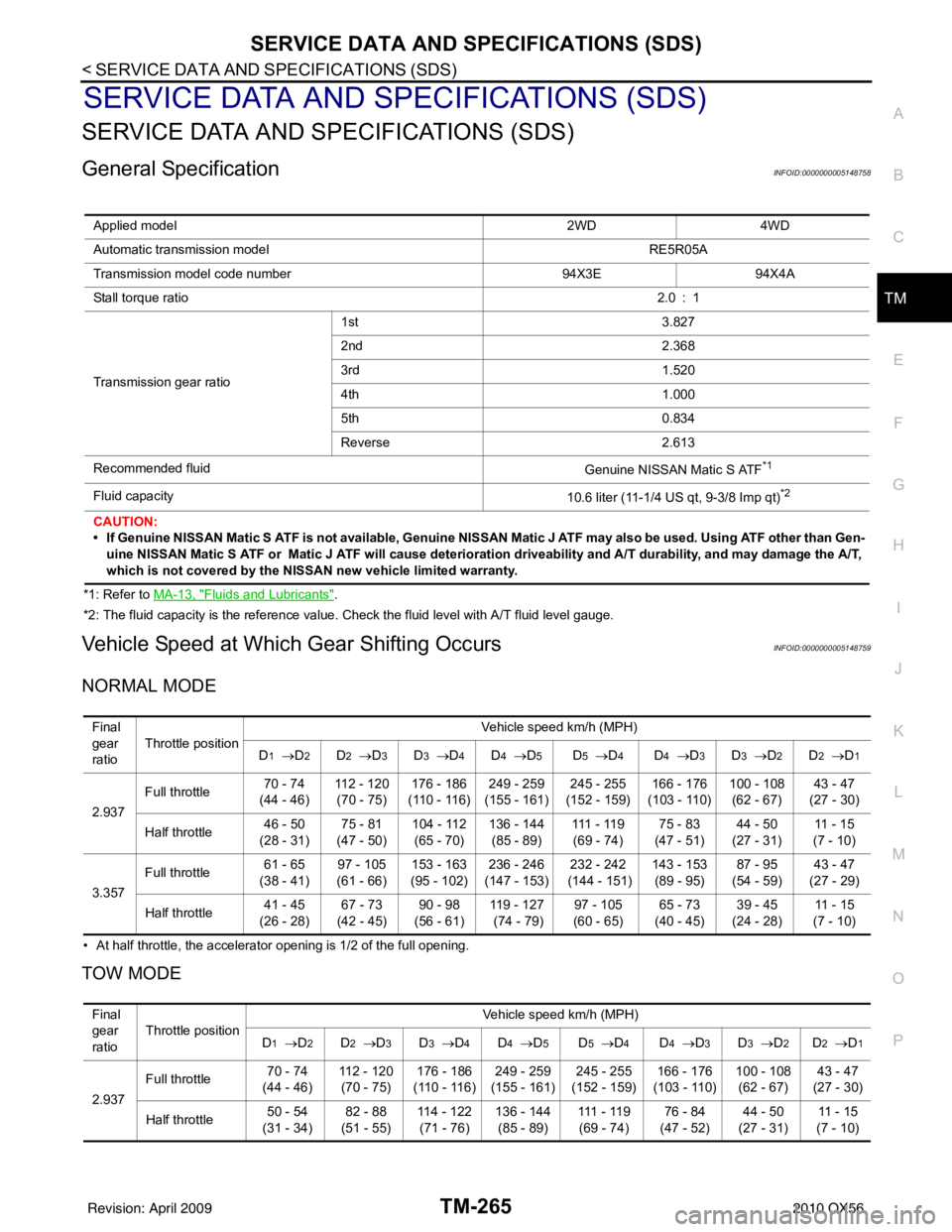
General SpecificationINFOID:0000000005148758
*1: Refer to MA-13, "Fluids and Lubricants".
*2: The fluid capacity is the reference value. Check the fluid level with A/T fluid level gauge.
Vehicle Speed at Which Gear Shifting OccursINFOID:0000000005148759
NORMAL MODE
• At half throttle, the accelerator opening is 1/2 of the full opening.
TOW MODE
Applied model 2WD4WD
Automatic transmission model RE5R05A
Transmission model code number 94X3E94X4A
Stall torque ratio 2.0 : 1
Transmission gear ratio 1st
3.827
2nd 2.368
3rd 1.520
4th 1.000
5th 0.834
Reverse 2.613
Recommended fluid Genuine NISSAN Matic S ATF
*1
Fluid capacity10.6 liter (11-1/4 US qt, 9-3/8 Imp qt)*2
CAUTION:
• If Genuine NISSAN Matic S ATF is not available, Genuine NISSAN Matic J ATF may also be used. Using ATF other than Gen-
uine NISSAN Matic S ATF or Matic J ATF will cause deterioration driveability and A/T durability, and may damage the A/T,
which is not covered by the NISSAN new vehicle limited warranty.
Final
gear
ratio Throttle position
Vehicle speed km/h (MPH)
D
1 → D2D2 →D3D3 →D4D4 →D5D5 →D4D4 →D3D3 → D2D2 →D1
2.937 Full throttle
70 - 74
(44 - 46) 112 - 120
(70 - 75) 176 - 186
(110 - 116) 249 - 259
(155 - 161) 245 - 255
(152 - 159) 166 - 176
(103 - 110) 100 - 108
(62 - 67) 43 - 47
(27 - 30)
Half throttle 46 - 50
(28 - 31) 75 - 81
(47 - 50) 104 - 112
(65 - 70) 136 - 144
(85 - 89) 111 - 11 9
(69 - 74) 75 - 83
(47 - 51) 44 - 50
(27 - 31) 11 - 1 5
(7 - 10)
3.357 Full throttle
61 - 65
(38 - 41) 97 - 105
(61 - 66) 153 - 163
(95 - 102) 236 - 246
(147 - 153) 232 - 242
(144 - 151) 143 - 153
(89 - 95) 87 - 95
(54 - 59) 43 - 47
(27 - 29)
Half throttle 41 - 45
(26 - 28) 67 - 73
(42 - 45) 90 - 98
(56 - 61) 11 9 - 1 2 7
(74 - 79) 97 - 105
(60 - 65) 65 - 73
(40 - 45) 39 - 45
(24 - 28) 11 - 1 5
(7 - 10)
Final
gear
ratio Throttle position Vehicle speed km/h (MPH)
D
1 → D2D2 →D3D3 →D4D4 →D5D5 →D4D4 →D3D3 → D2D2 →D1
2.937 Full throttle
70 - 74
(44 - 46) 112 - 120
(70 - 75) 176 - 186
(110 - 116) 249 - 259
(155 - 161) 245 - 255
(152 - 159) 166 - 176
(103 - 110) 100 - 108
(62 - 67) 43 - 47
(27 - 30)
Half throttle 50 - 54
(31 - 34) 82 - 88
(51 - 55) 114 - 122
(71 - 76) 136 - 144
(85 - 89) 111 - 11 9
(69 - 74) 76 - 84
(47 - 52) 44 - 50
(27 - 31) 11 - 1 5
(7 - 10)
Revision: April 20092010 QX56
Page 3962 of 4210
SERVICE DATA AND SPECIFICATIONS (SDS)TM-267
< SERVICE DATA AND SPECIFICATIONS (SDS)
CEF
G H
I
J
K L
M A
B
TM
N
O P
Total End PlayINFOID:0000000005148766
BEARING RACE FOR ADJUSTING TOTAL END PLAY
Torque ConverterINFOID:0000000005148767
Thickness of retaining plates Thickness mm (in)
4.2 (0.165)
4.4 (0.173)
4.6 (0.181)
4.8 (0.189)
5.0 (0.197)
5.2 (0.205)
5.4 (0.213)
Total end play mm (in) 0.25 – 0.55 (0.0098 – 0.0217)
Thickness mm (in)
0.8 (0.031)
1.0 (0.039)
1.2 (0.047)
1.4 (0.055)
1.6 (0.063)
1.8 (0.071)
Distance between end of converter housing and torque
converter mm (in) 24.0 (0.94)
Revision: April 20092010 QX56
Page 3979 of 4210
HEATER & COOLING UNIT ASSEMBLYVTL-17
< ON-VEHICLE REPAIR >
C
DE
F
G H
J
K L
M A
B
VTL
N
O P
Rear A/C System
NOTE:
Refer to HA-5, "
Precaution for Refrigerant Connection".
Removal and InstallationINFOID:0000000005147613
FRONT HEATER AND COOLING UNIT ASSEMBLY
Removal
7. High-pressure flexible hose 8. Low-pressure flexible hose 9. Low-pressure service valve
10. Low-pressure pipe 11. Expansion valve (front) 12. Drain hose
AWIIA0134GB
1. Rear heater and cooling unit assembly 2. Rear A/C pipes 3. Rear A/C heater core pipes
4. Rear heater core hose 5. Rear blower motor6. Underfloor rear A/C pipes
7. Underfloor rear heater core pipes A. Bolt torque specification B. Leak checking order (l - r)
C. Tightening torque D. Wrench sizeE. O-ring size
Front
NOTE: The O-ring size 8 is the high-side and the O-ring size 16 is the low-side.
Revision: April 20092010 QX56
Page 4118 of 4210

WHEEL AND TIRE ASSEMBLYWT-49
< ON-VEHICLE REPAIR >
C
DF
G H
I
J
K L
M A
B
WT
N
O P
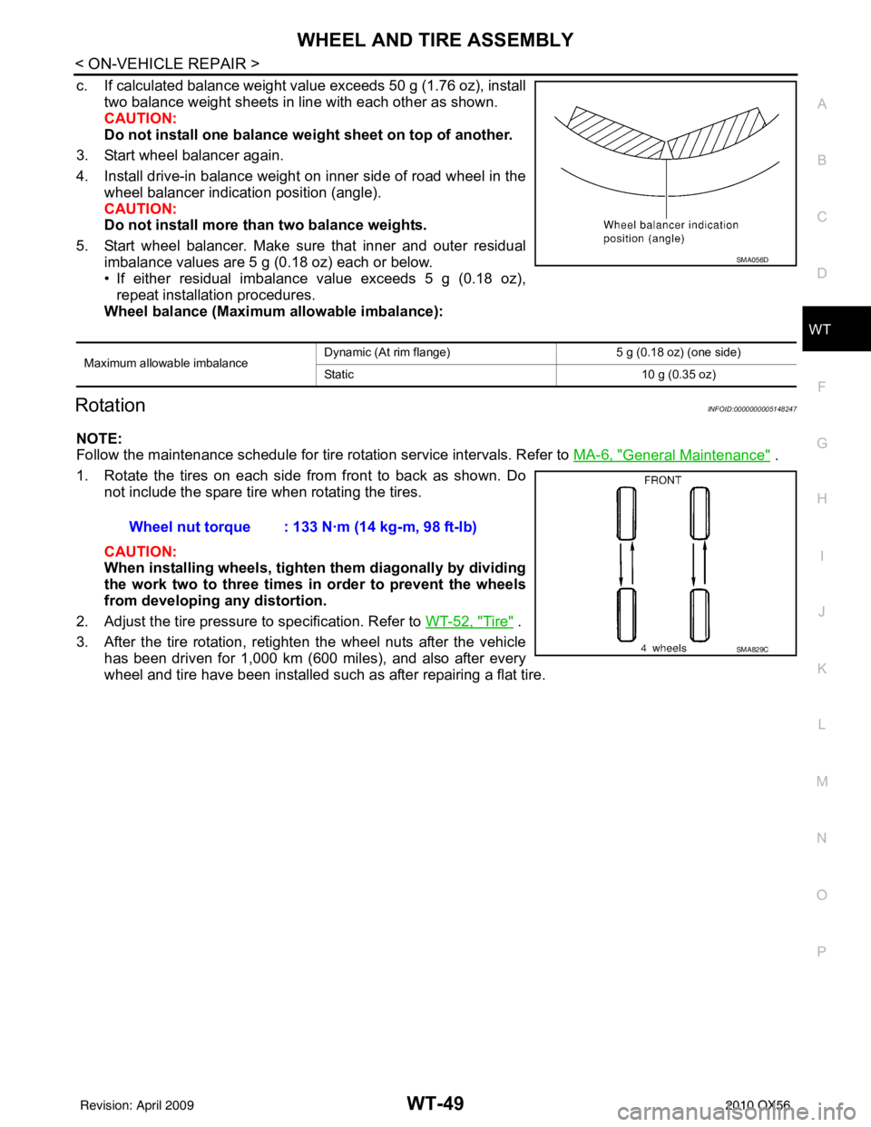
c. If calculated balance weight value exceeds 50 g (1.76 oz), install two balance weight sheets in line with each other as shown.
CAUTION:
Do not install one balance weig ht sheet on top of another.
3. Start wheel balancer again.
4. Install drive-in balance weight on inner side of road wheel in the wheel balancer indication position (angle).
CAUTION:
Do not install more than two balance weights.
5. Start wheel balancer. Make sure that inner and outer residual imbalance values are 5 g (0.18 oz) each or below.
• If either residual imbalance value exceeds 5 g (0.18 oz),repeat installation procedures.
Wheel balance (Maximum allowable imbalance):
RotationINFOID:0000000005148247
NOTE:
Follow the maintenance schedule for tire rotation service intervals. Refer to MA-6, "
General Maintenance" .
1. Rotate the tires on each side from front to back as shown. Do not include the spare tire when rotating the tires.
CAUTION:
When installing wheel s, tighten them diagonally by dividing
the work two to three times in order to prevent the wheels
from developing any distortion.
2. Adjust the tire pressure to specification. Refer to WT-52, "
Tire" .
3. After the tire rotation, retighten the wheel nuts after the vehicle has been driven for 1,000 km (600 miles), and also after every
wheel and tire have been installed such as after repairing a flat tire.
Maximum allowable imbalance Dynamic (At rim flange) 5 g (0.18 oz) (one side)
Static
10 g (0.35 oz)
SMA056D
Wheel nut torque : 133 N·m (14 kg-m, 98 ft-lb)
SMA829C
Revision: April 20092010 QX56