Page 2855 of 4210

MWI
THE OIL PRESSURE WARNING LAMP DOES NOT TURN ON
MWI-93
< SYMPTOM DIAGNOSIS >
C
D E
F
G H
I
J
K L
M B A
O P
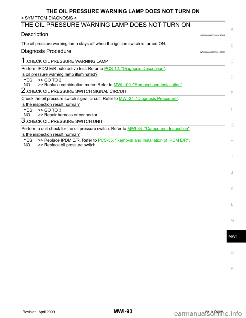
THE OIL PRESSURE WARNING LAMP DOES NOT TURN ON
DescriptionINFOID:0000000005146119
The oil pressure warning lamp stays off when the ignition switch is turned ON.
Diagnosis ProcedureINFOID:0000000005146120
1.CHECK OIL PRESSURE WARNING LAMP
Perform IPDM E/R auto active test. Refer to PCS-12, "
Diagnosis Description".
Is oil pressure warning lamp illuminated?
YES >> GO TO 2
NO >> Replace combination meter. Refer to MWI-100, "
Removal and Installation".
2.CHECK OIL PRESSURE SWITCH SIGNAL CIRCUIT
Check the oil pressure switch signal circuit. Refer to MWI-34, "
Diagnosis Procedure".
Is the inspection result normal?
YES >> GO TO 3
NO >> Repair harness or connector.
3.CHECK OIL PRESSURE SWITCH UNIT
Perform a unit check for the oil pressure switch. Refer to MWI-34, "
Component Inspection".
Is the inspection result normal?
YES >> Replace IPDM E/R. Refer to PCS-35, "Removal and Installation of IPDM E/R".
NO >> Replace oil pressure switch.
Revision: April 20092010 QX56
Page 2856 of 4210

MWI-94
< SYMPTOM DIAGNOSIS >
THE OIL PRESSURE WARNING LAMP DOES NOT TURN OFF
THE OIL PRESSURE WARNING LA MP DOES NOT TURN OFF
DescriptionINFOID:0000000005146121
The oil pressure warning lamp remains illuminated while the engine is running (normal oil pressure).
Diagnosis ProcedureINFOID:0000000005146122
Regarding Wiring Diagram information, refer to MWI-41, "Wiring Diagram".
1.CHECK OIL PRESSURE WARNING LAMP
Perform IPDM E/R auto active test. Refer to PCS-12, "
Diagnosis Description".
Is oil pressure warning lamp illuminated?
YES >> GO TO 2
NO >> Replace combination meter. Refer to MWI-100, "
Removal and Installation".
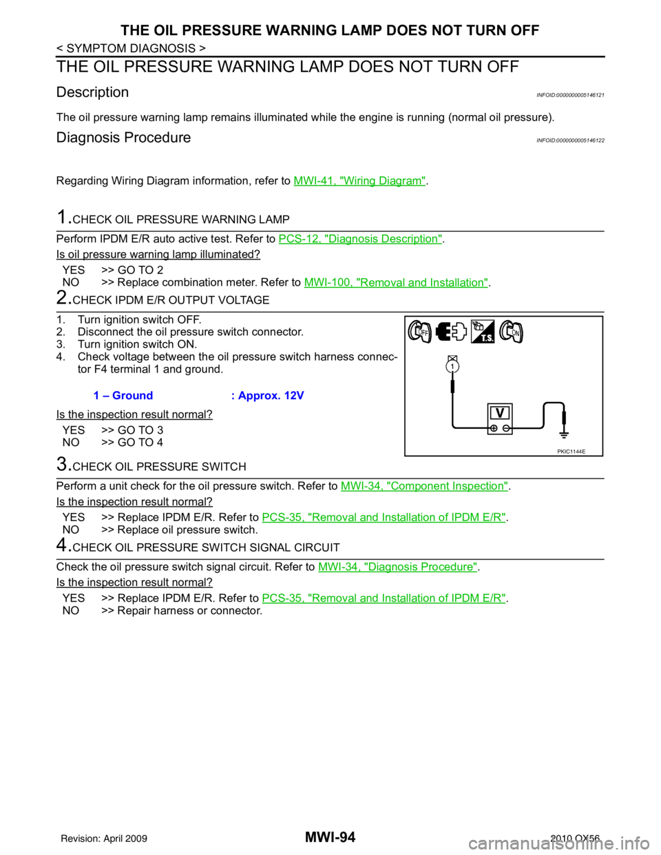
2.CHECK IPDM E/R OUTPUT VOLTAGE
1. Turn ignition switch OFF.
2. Disconnect the oil pressure switch connector.
3. Turn ignition switch ON.
4. Check voltage between the oil pressure switch harness connec- tor F4 terminal 1 and ground.
Is the inspection result normal?
YES >> GO TO 3
NO >> GO TO 4
3.CHECK OIL PRESSURE SWITCH
Perform a unit check for the oil pressure switch. Refer to MWI-34, "
Component Inspection".
Is the inspection result normal?
YES >> Replace IPDM E/R. Refer to PCS-35, "Removal and Installation of IPDM E/R".
NO >> Replace oil pressure switch.
4.CHECK OIL PRESSURE SWITCH SIGNAL CIRCUIT
Check the oil pressure switch signal circuit. Refer to MWI-34, "
Diagnosis Procedure".
Is the inspection result normal?
YES >> Replace IPDM E/R. Refer to PCS-35, "Removal and Installation of IPDM E/R".
NO >> Repair harness or connector. 1 – Ground
: Approx. 12V
PKIC1144E
Revision: April 20092010 QX56
Page 2887 of 4210
![INFINITI QX56 2010 Factory Service Manual PCS-12
< FUNCTION DIAGNOSIS >[IPDM E/R]
DIAGNOSIS SYSTEM (IPDM E/R)
DIAGNOSIS SYSTEM (IPDM E/R)
Diagnosis DescriptionINFOID:0000000005146506
AUTO ACTIVE TEST
Description
In auto active test mode, the INFINITI QX56 2010 Factory Service Manual PCS-12
< FUNCTION DIAGNOSIS >[IPDM E/R]
DIAGNOSIS SYSTEM (IPDM E/R)
DIAGNOSIS SYSTEM (IPDM E/R)
Diagnosis DescriptionINFOID:0000000005146506
AUTO ACTIVE TEST
Description
In auto active test mode, the](/manual-img/42/57032/w960_57032-2886.png)
PCS-12
< FUNCTION DIAGNOSIS >[IPDM E/R]
DIAGNOSIS SYSTEM (IPDM E/R)
DIAGNOSIS SYSTEM (IPDM E/R)
Diagnosis DescriptionINFOID:0000000005146506
AUTO ACTIVE TEST
Description
In auto active test mode, the IPDM
E/R sends a drive signal to the follo wing systems to check their operation.
• Oil pressure low/coolant pressure high warning indicator
• Oil pressure gauge
• Rear window defogger
• Front wipers
• Tail, license and parking lamps
• Front fog lamps
• Headlamps (Hi, Lo)
• A/C compressor (magnetic clutch)
• Cooling fan
Operation Procedure
1. Close the hood and front door RH, and lift the wiper a rms from the windshield (to prevent windshield dam-
age due to wiper operation).
NOTE:
When auto active test is performed with hood opened, sprinkle water on windshield before hand.
2. Turn ignition switch OFF.
3. Turn the ignition switch ON and, within 20 seconds, press the front door switch LH 10 times. Then turn the ignition switch OFF.
4. Turn the ignition switch ON within 10 seconds. Af ter that the horn sounds once and the auto active test
starts.
5. After a series of the following operations is repeated 3 times, auto active test is completed.
NOTE:
When auto active test mode has to be cancelled halfway through test, turn ignition switch OFF.
CAUTION:
• If auto active test mode cannot be actuated, check door switch system. Refer to DLK-71, "
Descrip-
tion".
• Do not start the engine.
Inspection in Auto Active Test Mode
When auto active test mode is actuated, the following 7 steps are repeated 3 times.
Operation
sequence Inspection Location
Operation
1 Rear window defogger 10 seconds
2 Front wipers LO for 5 seconds → HI for 5 seconds
WKIA4655E
Revision: April 20092010 QX56
Page 3179 of 4210

PRECAUTIONSRF-51
< PRECAUTION >
C
DE
F
G H
I
J
L
M A
B
RF
N
O P
5. When the repair work is completed, return the ignition switch to the ″LOCK ″ position before connecting
the battery cables. (At this time, the steering lock mechanism will engage.)
6. Perform a self-diagnosis check of al l control units using CONSULT-III.
PrecautionINFOID:0000000005147304
• Disconnect both battery cables in advance.
• Never tamper with or force air bag lid open, as this may adversely affect air bag performance.
• Be careful not to scratch pad and other parts.
• When removing or disassembling any part, be careful not to damage or deform it. Protect parts which may
get in the way with cloth.
• When removing parts with a screwdriver or other tool , protect parts by wrapping them with vinyl or tape.
• Keep removed parts protected with cloth.
• If a clip is deformed or damaged, replace it.
• If an unreusable part is removed, replace it with a new one.
• Tighten bolts and nuts firmly to the specified torque.
• After re-assembly has been completed, make sure each part functions correctly.
• Remove stains in the following way.
Water-soluble stains:
Dip a soft cloth in warm water, and then squeeze it tight ly. After wiping the stain, wipe with a soft dry cloth.
Oil stain:
Dissolve a synthetic detergent in warm water (density of 2 to 3% or less), dip the cloth, then clean off the stain
with the cloth. Next, dip the cloth in fresh water and squeeze it tightly. Then clean off the detergent completely.
Then wipe the area with a soft dry cloth.
• Do not use any organic solvent, such as thinner or benzine.
Revision: April 20092010 QX56
Page 3190 of 4210

PRECAUTIONSRSU-3
< PRECAUTION >
C
DF
G H
I
J
K L
M A
B
RSU
N
O P
5. When the repair work is completed, return the ignition switch to the ″LOCK ″ position before connecting
the battery cables. (At this time, the steering lock mechanism will engage.)
6. Perform a self-diagnosis check of al l control units using CONSULT-III.
Precaution for Rear SuspensionINFOID:0000000005148126
• When installing the rubber bushings, the final tightening must be done under unladen condition and with the
tires on level ground. Oil will shorten the life of the rubber bushings, so wipe off any spilled oil immediately.
• Unladen condition means the fuel tank, engine coolant and lubricants are at the full specification. The spare
tire, jack, hand tools, and mats are in their designated positions.
• After installing suspension components, check the wheel alignment.
• Caulking nuts are not reusable. Always use new caulking nuts for installation. New caulking nuts are pre- oiled, do not apply any additional lubrication.
Revision: April 20092010 QX56
Page 3200 of 4210

REAR SUSPENSION MEMBERRSU-13
< REMOVAL AND INSTALLATION >
C
DF
G H
I
J
K L
M A
B
RSU
N
O P
• Do not crimp or stretch the brake hose when re positioning the brake caliper out of the way.
• Do not press brake pedal while the brake caliper is removed.
7. Remove the spare tire.
8. Disconnect the two rear ABS sensor electrical connectors.
9. Remove the two rear drive shafts. Refer to RAX-10, "
Removal and Installation" .
10. Remove the rear final drive. Refer to DLN-250, "
Removal and Installation" .
11. Remove the EVAP canister bolt from the top of the rear suspension member.
12. Disconnect the parking brake cables from the brackets on the rear suspension member.
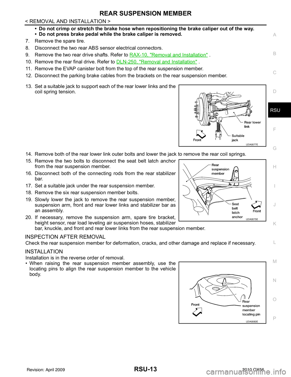
13. Set a suitable jack to support each of the rear lower links and the coil spring tension.
14. Remove both of the rear lower link outer bolts and lower the jack to remove the rear coil springs.
15. Remove the two bolts to disconnect the seat belt latch anchor from the rear suspension member.
16. Disconnect both of the connecting rods from the rear stabilizer
bar.
17. Set a suitable jack under the rear suspension member.
18. Remove the six rear suspension member bolts.
19. Slowly lower the jack to remove the rear suspension member, suspension arm, front and rear lower links and stabilizer bar as
an assembly.
20. If necessary, remove the suspension arm, spare tire bracket, height sensor, rear load leveling air suspension hoses, stabilizer
bar, knuckle, and front and rear lower links from the rear suspension member.
INSPECTION AFTER REMOVAL
Check the rear suspension member for deformation, cracks, and other damage and replace if necessary.
INSTALLATION
Installation is in the reverse order of removal.
• When raising the rear suspension member assembly, use the
locating pins to align the rear suspension member to the vehicle
body.
LEIA0077E
LEIA0075E
LEIA0083E
Revision: April 20092010 QX56
Page 3201 of 4210
RSU-14
< REMOVAL AND INSTALLATION >
REAR SUSPENSION MEMBER
• When installing the upper and lower rubber seats for the rear coilsprings, the arrow embossed on the rubber seats must point out
toward the wheel and tire assembly.
• To connect the rear load leveling air suspension hoses, the lock ring must be fully seated in the fitt ing. Insert the hose (B) into the
lock ring (A) until the lock ring (A) is touching the hose (B) as
shown. Pull on the hose to check that it is securely inserted.
• Perform the final tightening of the nuts and bolts for the links (rubber bushing) under unladen condition (unladen condition means that the fuel tank, engine cool ant and lubricants are at the full specification, and
the spare tire, jack, hand tools, and mats are in t heir designated positions) with the tires on level ground.
• Check the wheel alignment. Refer to RSU-6, "
Wheel Alignment Inspection" .
LEIA0076E
LEIA0078E
Revision: April 20092010 QX56
Page 3209 of 4210
RSU-22
< REMOVAL AND INSTALLATION >
REAR LOWER LINK & COIL SPRING
8. Remove the rear lower link adjusting bolt and nut from the rearsuspension member using power tool, then remove the rear
lower link.
INSPECTION AFTER REMOVAL
Check the coil spring and rubber seats for deformation, cracks, or other damage and replace if necessary.
INSTALLATION
Installation is in the reverse order of removal.
• Tighten the nuts and bolts to specification. Refer to RSU-9, "
Component" .
• When installing the upper and lower rubber seats for the rear coil springs, the arrow embossed on the rubber seats must point out
toward the wheel and tire assembly.
• After installing the rear lower link and coil spring, check the wheel alignment and adjust if necessary. Refer to RSU-6, "
Wheel Align-
ment Inspection"
LEIA0009E
LEIA0076E
Revision: April 20092010 QX56