2010 INFINITI QX56 steering wheel
[x] Cancel search: steering wheelPage 2688 of 4210
LU-2
< PRECAUTION >
PRECAUTIONS
PRECAUTION
PRECAUTIONS
Precaution for Supplemental Restraint System (SRS) "AIR BAG" and "SEAT BELT
PRE-TENSIONER"
INFOID:0000000005260134
The Supplemental Restraint System such as “A IR BAG” and “SEAT BELT PRE-TENSIONER”, used along
with a front seat belt, helps to reduce the risk or severity of injury to the driver and front passenger for certain
types of collision. This system includes seat belt switch inputs and dual stage front air bag modules. The SRS
system uses the seat belt switches to determine the front air bag deployment, and may only deploy one front
air bag, depending on the severity of a collision and w hether the front occupants are belted or unbelted.
Information necessary to service the system safely is included in the SR and SB section of this Service Man-
ual.
WARNING:
• To avoid rendering the SRS inopera tive, which could increase the risk of personal injury or death in
the event of a collision which would result in air bag inflation, all maintenance must be performed by
an authorized NISSAN/INFINITI dealer.
• Improper maintenance, including in correct removal and installation of the SRS, can lead to personal
injury caused by unintent ional activation of the system. For re moval of Spiral Cable and Air Bag
Module, see the SR section.
• Do not use electrical test equipmen t on any circuit related to the SRS unless instructed to in this
Service Manual. SRS wiring harn esses can be identified by yellow and/or orange harnesses or har-
ness connectors.
PRECAUTIONS WHEN USING POWER TOOLS (AIR OR ELECTRIC) AND HAMMERS
WARNING:
• When working near the Airbag Diagnosis Sensor Unit or other Airbag System sensors with the Igni-
tion ON or engine running, DO NOT use air or electri c power tools or strike near the sensor(s) with a
hammer. Heavy vibration could activate the sensor( s) and deploy the air bag(s), possibly causing
serious injury.
• When using air or electric power tools or hammers , always switch the Ignition OFF, disconnect the
battery, and wait at least 3 minu tes before performing any service.
Precaution Necessary for Steering W heel Rotation After Battery Disconnect
INFOID:0000000005260135
NOTE:
• This Procedure is applied only to models with Intelligent Key system and NATS (NISSAN ANTI-THEFT SYS-
TEM).
• Remove and install all control units after disconnecting both battery cables with the ignition knob in the
″LOCK ″ position.
• Always use CONSULT-III to perform self-diagnosis as a part of each function inspection after finishing work.
If DTC is detected, perform trouble diagnosis according to self-diagnostic results.
For models equipped with the Intelligent Key system and NATS, an electrically controlled steering lock mech-
anism is adopted on the key cylinder.
For this reason, if the battery is disconnected or if the battery is discharged, the steering wheel will lock and
steering wheel rotation will become impossible.
If steering wheel rotation is required when battery pow er is interrupted, follow the procedure below before
starting the repair operation.
OPERATION PROCEDURE
1. Connect both battery cables. NOTE:
Supply power using jumper cables if battery is discharged.
2. Use the Intelligent Key or mechanical key to turn the ignition switch to the ″ACC ″ position. At this time, the
steering lock will be released.
3. Disconnect both battery cables. The steering lock will remain released and the steering wheel can be rotated.
4. Perform the necessary repair operation.
Revision: April 20092010 QX56
Page 2705 of 4210
MA-1
MAINTENANCE
C
DE
F
G H
I
J
K L
M B
MA
SECTION MA
N
O A
CONTENTS
MAINTENANCE
PRECAUTION .......
........................................3
PRECAUTIONS .............................................. .....3
Precaution for Supplemental Restraint System
(SRS) "AIR BAG" and "SEAT BELT PRE-TEN-
SIONER" ............................................................. ......
3
Precaution Necessary for Steering Wheel Rota-
tion After Battery Disconnect ............................... ......
3
PREPARATION ............................................5
PREPARATION .............................................. .....5
Special Service Tool ........................................... ......5
Commercial Service Tool ..........................................5
ON-VEHICLE MAINTENANCE .....................6
GENERAL MAINTE NANCE ........................... .....6
General Maintenance .......................................... ......6
PERIODIC MAINTENANCE ................................9
Introduction of Periodic Maintenance .................. ......9
Maintenance for Off-road Driving (4WD only) ...........9
Schedule 1 ................................................................9
Schedule 2 ..............................................................11
RECOMMENDED FLUIDS AND LUBRI-
CANTS ................................................................
13
Fluids and Lubricants .......................................... ....13
Engine Oil Recommendation ..................................14
ENGINE MAINTENANCE ...................................15
DRIVE BELTS ....................................................... ....15
DRIVE BELTS : Exploded View ..............................15
DRIVE BELTS : Checking Drive Belts ....................15
ENGINE COOLANT ............................................... ....15
ENGINE COOLANT : Inspection .............................15
ENGINE COOLANT : Changing Engine Coolant ....17
FUEL LINES .......................................................... ....19
FUEL LINES : Checking Fuel Line ..........................19
FUEL FILTER ......................................................... ....19
FUEL FILTER : Changing Fuel Filter .......................19
AIR CLEANER FILTER ......................................... ....19
AIR CLEANER FILTER : Exploded View ................20
AIR CLEANER FILTER : Removal and Installation
(Viscous paper type) ................................................
20
ENGINE OIL ........................................................... ....20
ENGINE OIL : Inspection .........................................20
ENGINE OIL : Changing Engine Oil ........................22
OIL FILTER ............................................................ ....22
OIL FILTER : Removal and Installation ...................22
SPARK PLUG ........................................................ ....23
SPARK PLUG : Exploded View ...............................24
SPARK PLUG : Removal and Installation ...............24
EVAP VAPOR LINES ............................................ ....25
EVAP VAPOR LINES : Checking EVAP Vapor
Line ..........................................................................
25
CHASSIS AND BODY MAINTENANCE ...........26
IN-CABIN MICROFILTER ...................................... ....26
IN-CABIN MICROFILTER : Removal and Installa-
tion ....................................................................... ....
26
EXHAUST SYSTEM ...................................................26
EXHAUST SYSTEM : Checking Exhaust System ....26
A/T FLUID .............................................................. ....27
A/T FLUID : Checking the A/T Fluid (ATF) ..............27
A/T FLUID : Changing the A/T Fluid (ATF) ..............29
TRANSFER FLUID ................................................ ....30
TRANSFER FLUID : Replacement ..........................30
TRANSFER FLUID : Inspection ..............................30
PROPELLER SHAFT ............................................. ....31
PROPELLER SHAFT : Checking Propeller Shaft ....31
DIFFERENTIAL GEAR OIL ................................... ....31
Revision: April 20092010 QX56
Page 2706 of 4210

MA-2
DIFFERENTIAL GEAR OIL : Changing Front Dif-
ferential Gear Oil ....................................................
31
DIFFERENTIAL GEAR OIL : Checking Front Dif-
ferential Gear Oil ....................................................
31
DIFFERENTIAL GEAR OIL : Changing Rear Dif-
ferential Gear Oil ....................................................
32
DIFFERENTIAL GEAR OIL : Checking Rear Dif-
ferential Gear Oil ....................................................
32
WHEELS ................................................................ ...32
WHEELS : Balancing Wheels .................................32
WHEELS : Rotation ................................................34
BRAKE FLUID LEVEL AND LEAKS ........................34
BRAKE FLUID LEVEL AND LEAKS : On Board In-
spection ............................................................... ...
34
BRAKE LINES AND CABLES ............................... ...34
BRAKE LINES AND CABLES : Checking Brake
Line and Cables ......................................................
34
DISC BRAKE ......................................................... ...34
DISC BRAKE : Front Pad Inspection ......................35
DISC BRAKE : Front Rotor Inspection ...................35
DISC BRAKE : Rear Pad Inspection ......................35
DISC BRAKE : Rear Rotor Inspection ....................36
STEERING GEAR AND LINKAGE ........................ ...36
STEERING GEAR AND LINKAGE : Checking
Steering Gear and Linkage .....................................
36
POWER STEERING FLUID AND LINES ............... ...37
POWER STEERING FLUID AND LINES : Check-
ing Fluid Level .........................................................
37
POWER STEERING FLUID AND LINES : Check-
ing Fluid Leakage ....................................................
37
AXLE AND SUSPENSION PARTS ........................ ...37
AXLE AND SUSPENSION PARTS : Checking
Axle and Suspension Parts .................................. ...
37
LOCKS AND HINGES ............................................ ...38
LOCKS AND HINGES : Lubricating Locks, Hinges
and Hood Latches ...................................................
38
SEAT BELT, BUCKLES, RETRACTORS, AN-
CHORS AND ADJUSTERS ................................... ...
39
SEAT BELT, BUCKLES, RETRACTORS, AN-
CHORS AND ADJUSTERS : Checking Seat
Belts, Buckles, Retractors, Anchors and Adjusters
...
39
Revision: April 20092010 QX56
Page 2707 of 4210
PRECAUTIONSMA-3
< PRECAUTION >
C
DE
F
G H
I
J
K L
M B
MA
N
O A
PRECAUTION
PRECAUTIONS
Precaution for Supplemental
Restraint System (SRS) "AIR BAG" and "SEAT BELT
PRE-TENSIONER"
INFOID:0000000005403129
The Supplemental Restraint System such as “AIR BAG” and “SEAT BELT PRE-TENSIONER”, used along
with a front seat belt, helps to reduce the risk or severi ty of injury to the driver and front passenger for certain
types of collision. This system includes seat belt switch inputs and dual stage front air bag modules. The SRS
system uses the seat belt switches to determine the front air bag deployment, and may only deploy one front
air bag, depending on the severity of a collision and w hether the front occupants are belted or unbelted.
Information necessary to service the system safely is included in the SR and SB section of this Service Man-
ual.
WARNING:
• To avoid rendering the SRS inoper ative, which could increase the risk of personal injury or death in
the event of a collision which would result in air bag inflation, all maintenance must be performed by
an authorized NISSAN/INFINITI dealer.
• Improper maintenance, including in correct removal and installation of the SRS, can lead to personal
injury caused by unintentional act ivation of the system. For removal of Spiral Cable and Air Bag
Module, see the SR section.
• Do not use electrical test equipm ent on any circuit related to the SRS unless instructed to in this
Service Manual. SRS wiring harnesses can be identi fied by yellow and/or orange harnesses or har-
ness connectors.
PRECAUTIONS WHEN USING POWER TOOLS (AIR OR ELECTRIC) AND HAMMERS
WARNING:
• When working near the Airbag Diagnosis Sensor Un it or other Airbag System sensors with the Igni-
tion ON or engine running, DO NOT use air or el ectric power tools or strike near the sensor(s) with a
hammer. Heavy vibration could activate the sensor( s) and deploy the air bag(s), possibly causing
serious injury.
• When using air or electric power tools or hammers, always switch the Ignition OFF, disconnect the battery, and wait at least 3 minutes before performing any service.
Precaution Necessary for Steering Wheel Rotation After Battery Disconnect
INFOID:0000000005403130
NOTE:
• This Procedure is applied only to models with Intelligent Key system and NATS (NISSAN ANTI-THEFT SYS-
TEM).
• Remove and install all control units after disconnecti ng both battery cables with the ignition knob in the
″ LOCK ″ position.
• Always use CONSULT-III to perform self-diagnosis as a part of each function inspection after finishing work.
If DTC is detected, perform trouble diagnosis according to self-diagnostic results.
For models equipped with the Intelligent Key system and NATS , an electrically controlled steering lock mech-
anism is adopted on the key cylinder.
For this reason, if the battery is disconnected or if the battery is discharged, the steering wheel will lock and
steering wheel rotation will become impossible.
If steering wheel rotation is required when battery power is interrupted, follow the procedure below before
starting the repair operation.
OPERATION PROCEDURE
1. Connect both battery cables. NOTE:
Supply power using jumper cables if battery is discharged.
2. Use the Intelligent Key or mechanical key to turn the ignition switch to the ″ACC ″ position. At this time, the
steering lock will be released.
3. Disconnect both battery cables. The steering lock will remain released and the steering wheel can be
rotated.
4. Perform the necessary repair operation.
Revision: April 20092010 QX56
Page 2710 of 4210
MA-6
< ON-VEHICLE MAINTENANCE >
GENERAL MAINTENANCE
ON-VEHICLE MAINTENANCE
GENERAL MAINTENANCE
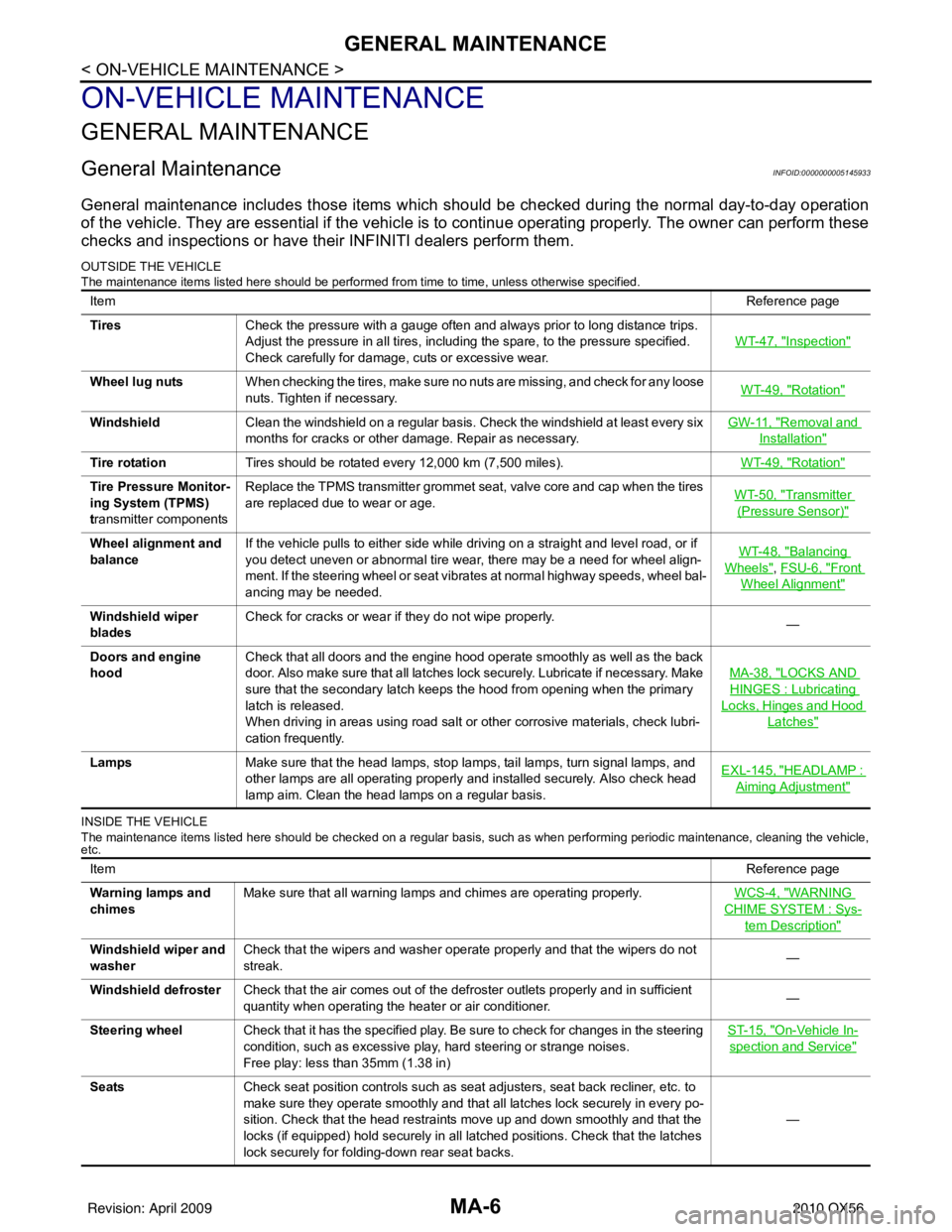
General MaintenanceINFOID:0000000005145933
General maintenance includes those items which should be checked during the normal day-to-day operation
of the vehicle. They are essential if the vehicle is to continue operating properly. The owner can perform these
checks and inspections or have thei r INFINITI dealers perform them.
OUTSIDE THE VEHICLE
The maintenance items listed here should be performed fr om time to time, unless otherwise specified.
INSIDE THE VEHICLE
The maintenance items listed here should be checked on a regular basis, such as when performing periodic maintenance, cleaning the vehicle,
etc.
Item Reference page
Tires Check the pressure with a gauge often and always prior to long distance trips.
Adjust the pressure in all tires, including the spare, to the pressure specified.
Check carefully for damage, cuts or excessive wear. WT-47, "
Inspection"
Wheel lug nuts
When checking the tires, make sure no nuts are missing, and check for any loose
nuts. Tighten if necessary. WT-49, "Rotation"
Windshield
Clean the windshield on a regular basis. Check the windshield at least every six
months for cracks or other damage. Repair as necessary. GW-11, "Removal and
Installation"
Tire rotation
Tires should be rotated every 12,000 km (7,500 miles). WT-49, "Rotation"
Tire Pressure Monitor-
ing System (TPMS)
transmitter componentsReplace the TPMS transmitter grommet seat, valve core and cap when the tires
are replaced due to wear or age.
WT-50, "Transmitter
(Pressure Sensor)"
Wheel alignment and
balanceIf the vehicle pulls to either side while driving on a straight and level road, or if
you detect uneven or abnormal tire wear, there may be a need for wheel align-
ment. If the steering wheel or seat vibrates at normal highway speeds, wheel bal-
ancing may be needed. WT-48, "Balancing
Wheels", FSU-6, "Front
Wheel Alignment"
Windshield wiper
blades
Check for cracks or wear if they do not wipe properly.
—
Doors and engine
hood Check that all doors and the engine hood operate smoothly as well as the back
door. Also make sure that all latches lock securely. Lubricate if necessary. Make
sure that the secondary latch keeps the hood from opening when the primary
latch is released.
When driving in areas using road salt or other corrosive materials, check lubri-
cation frequently. MA-38, "
LOCKS AND
HINGES : Lubricating
Locks, Hinges and Hood
Latches"
Lamps
Make sure that the head lamps, stop lamps, tail lamps, turn signal lamps, and
other lamps are all operating properly and installed securely. Also check head
lamp aim. Clean the head lamps on a regular basis. EXL-145, "HEADLAMP :
Aiming Adjustment"
Item
Reference page
Warning lamps and
chimes Make sure that all warning lamps and chimes are operating properly.
WCS-4, "
WARNING
CHIME SYSTEM : Sys-
tem Description"
Windshield wiper and
washerCheck that the wipers and washer operate properly and that the wipers do not
streak.
—
Windshield defroster Check that the air comes out of the defroster outlets properly and in sufficient
quantity when operating the heater or air conditioner. —
Steering wheel Check that it has the specified play. Be sure to check for changes in the steering
condition, such as excessive play, hard steering or strange noises.
Free play: less than 35mm (1.38 in) ST-15, "
On-Vehicle In-
spection and Service"
Seats
Check seat position controls such as seat adjusters, seat back recliner, etc. to
make sure they operate smoothly and that all latches lock securely in every po-
sition. Check that the head restraints move up and down smoothly and that the
locks (if equipped) hold securely in all latched positions. Check that the latches
lock securely for folding-down rear seat backs. —
Revision: April 20092010 QX56
Page 2740 of 4210
MA-36
< ON-VEHICLE MAINTENANCE >
CHASSIS AND BODY MAINTENANCE
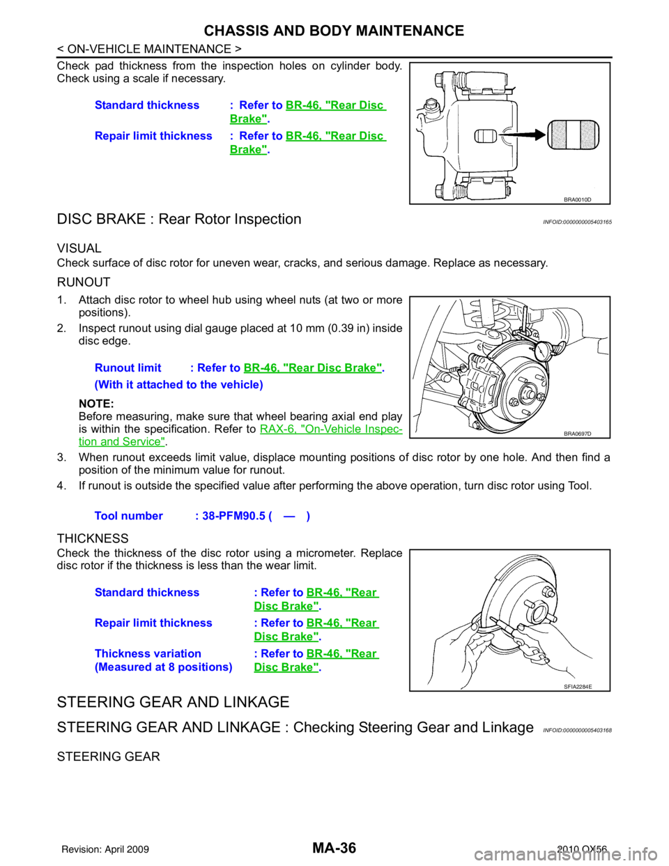
Check pad thickness from the inspection holes on cylinder body.
Check using a scale if necessary.
DISC BRAKE : Rear Rotor InspectionINFOID:0000000005403165
VISUAL
Check surface of disc rotor for uneven wear, cracks, and serious damage. Replace as necessary.
RUNOUT
1. Attach disc rotor to wheel hub using wheel nuts (at two or more
positions).
2. Inspect runout using dial gauge placed at 10 mm (0.39 in) inside disc edge.
NOTE:
Before measuring, make sure that wheel bearing axial end play
is within the specification. Refer to RAX-6, "
On-Vehicle Inspec-
tion and Service".
3. When runout exceeds limit value, displace mounting positions of disc rotor by one hole. And then find a position of the minimum value for runout.
4. If runout is outside the specified value after performing the above operation, turn disc rotor using Tool.
THICKNESS
Check the thickness of the disc rotor using a micrometer. Replace
disc rotor if the thickness is less than the wear limit.
STEERING GEAR AND LINKAGE
STEERING GEAR AND LINKAGE : Che cking Steering Gear and LinkageINFOID:0000000005403168
STEERING GEAR
Standard thickness : Refer to BR-46, "Rear Disc
Brake".
Repair limit thickness : Refer to BR-46, "
Rear Disc
Brake".
BRA0010D
Runout limit : Refer to BR-46, "Rear Disc Brake".
(With it attached to the vehicle)
Tool number : 38-PFM90.5 ( — )
BRA0697D
Standard thickness : Refer to BR-46, "Rear
Disc Brake".
Repair limit thickness : Refer to BR-46, "
Rear
Disc Brake".
Thickness variation
(Measured at 8 positions) : Refer to BR-46, "
Rear
Disc Brake".
SFIA2284E
Revision: April 20092010 QX56
Page 2741 of 4210
CHASSIS AND BODY MAINTENANCEMA-37
< ON-VEHICLE MAINTENANCE >
C
DE
F
G H
I
J
K L
M B
MA
N
O A
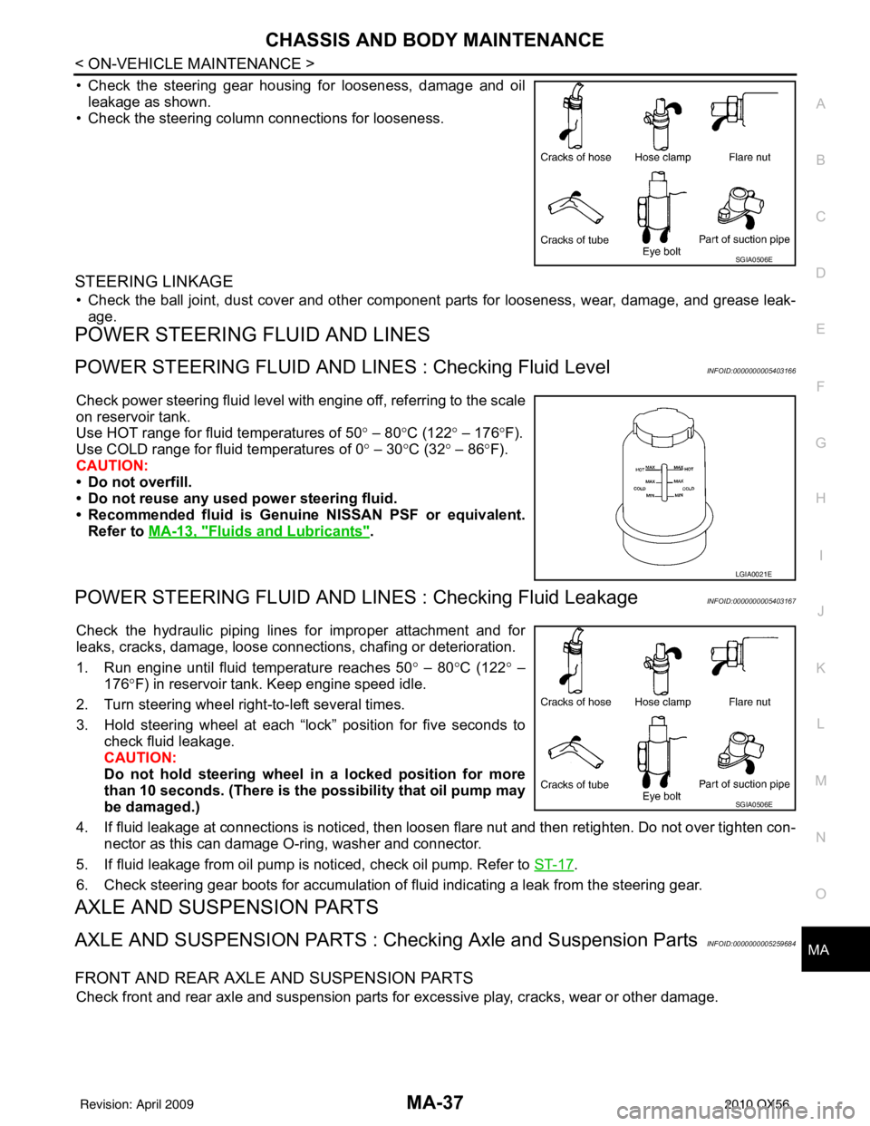
• Check the steering gear housing for looseness, damage and oil
leakage as shown.
• Check the steering column connections for looseness.
STEERING LINKAGE
• Check the ball joint, dust cover and other component parts for looseness, wear, damage, and grease leak-
age.
POWER STEERING FLUID AND LINES
POWER STEERING FLUID AND LINE S : Checking Fluid LevelINFOID:0000000005403166
Check power steering fluid level with engine off, referring to the scale
on reservoir tank.
Use HOT range for fluid temperatures of 50 ° – 80 °C (122 ° – 176 °F).
Use COLD range for fluid temperatures of 0 ° – 30 °C (32° – 86°F).
CAUTION:
• Do not overfill.
• Do not reuse any used power steering fluid.
• Recommended fluid is Genuine NISSAN PSF or equivalent.
Refer to MA-13, "
Fluids and Lubricants".
POWER STEERING FLUID AND LINES : Checking Fluid LeakageINFOID:0000000005403167
Check the hydraulic piping lines for improper attachment and for
leaks, cracks, damage, loose connec tions, chafing or deterioration.
1. Run engine until fluid temperature reaches 50 ° – 80° C (122° –
176° F) in reservoir tank. Keep engine speed idle.
2. Turn steering wheel right-to-left several times.
3. Hold steering wheel at each “lock” position for five seconds to check fluid leakage.
CAUTION:
Do not hold steering wheel in a locked position for more
than 10 seconds. (There is the possibility that oil pump may
be damaged.)
4. If fluid leakage at connections is noticed, then loosen flare nut and then retighten. Do not over tighten con- nector as this can damage O-ring, washer and connector.
5. If fluid leakage from oil pump is noticed, check oil pump. Refer to ST-17
.
6. Check steering gear boots for accumulation of fluid indicating a leak from the steering gear.
AXLE AND SUSPENSION PARTS
AXLE AND SUSPENSION PARTS : Chec king Axle and Suspension PartsINFOID:0000000005259684
FRONT AND REAR AXLE AND SUSPENSION PARTS
Check front and rear axle and suspension parts for excessive play, cracks, wear or other damage.
SGIA0506E
LGIA0021E
SGIA0506E
Revision: April 20092010 QX56
Page 2744 of 4210
MIR-1
DRIVER CONTROLS
C
DE
F
G H
I
J
K
M
SECTION MIR
A
B
MIR
N
O P
CONTENTS
MIRRORS
COMPONENT DIAGNOSIS ..........................2
DOOR MIRROR .............................................. .....2
Wiring Diagram ................................................... ......2
INSIDE MIRROR .................................................5
Wiring Diagram ................................................... ......5
PRECAUTION ...............................................8
PRECAUTIONS .............................................. .....8
Precaution for Supplemental Restraint System
(SRS) "AIR BAG" and "SEAT BELT PRE-TEN-
SIONER" ............................................................. ......
8
Precaution Necessary for Steering Wheel Rota-
tion After Battery Disconnect ............................... ......
8
Handling for Adhesive and Primer ............................9
PREPARATION ...........................................10
PREPARATION .............................................. ....10
Special Service Tool ............................................ ....10
Commercial Service Tool ........................................10
REMOVAL AND INSTALLATION ...............11
INSIDE MIRROR ...............................................11
Wiring Diagram - I/MIRR - ................................... ....11
Removal and Installation .........................................12
DOOR MIRROR ................................................13
Wiring Diagram - MIRROR -Without Power Fold-
ing Mirrors ................................................................
13
Wiring Diagram - H/MIRR - ......................................15
Door Mirror Assembly ..............................................17
Door Mirror Glass ....................................................17
DISASSEMBLY AND ASSEMBLY ..............19
DOOR MIRROR ................................................19
Mirror Actuator ..................................................... ....19
Revision: April 20092010 QX56