2010 INFINITI QX56 engine oil
[x] Cancel search: engine oilPage 2725 of 4210
ENGINE MAINTENANCEMA-21
< ON-VEHICLE MAINTENANCE >
C
DE
F
G H
I
J
K L
M B
MA
N
O A
• If the engine oil is milky, it is highly probable that it is contaminated with engine coolant. Repair the broken
parts.
OIL LEAKAGE
Check for oil leakage around the following areas:
•Oil pan
• Oil pan drain plug
• Oil pressure switch
• Oil filter
• Oil cooler
• Intake valve timing control cover
• Intake valve timing control solenoid valve
• Front cover
• Mating surface between cylinder block and cylinder head
• Mating surface between cylinder head and rocker cover
• Crankshaft oil seal (front and rear)
OIL PRESSURE CHECK
WARNING:
• Be careful not to burn yoursel f, as engine oil may be hot.
• Put the selector lever in the Park “P” position.
1. Check the engine oil level. Refer to MA-20, "
ENGINE OIL : Inspection".
2. Remove engine front undercover using power tool.
3. Disconnect the oil pressure switch harness connector.
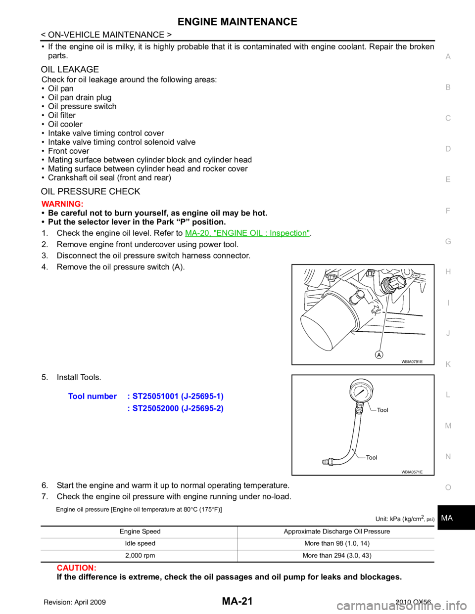
4. Remove the oil pressure switch (A).
5. Install Tools.
6. Start the engine and warm it up to normal operating temperature.
7. Check the engine oil pressure with engine running under no-load.
Engine oil pressure [Engine oil temperature at 80 °C (175 °F)]
Unit: kPa (kg/cm2, psi)
CAUTION:
If the difference is extreme, check the oil passages and oil pump for leaks and blockages.
WBIA0791E
Tool number : ST25051001 (J-25695-1)
: ST25052000 (J-25695-2)
WBIA0571E
Engine Speed Approximate Discharge Oil Pressure
Idle speed More than 98 (1.0, 14)
2,000 rpm More than 294 (3.0, 43)
Revision: April 20092010 QX56
Page 2726 of 4210
MA-22
< ON-VEHICLE MAINTENANCE >
ENGINE MAINTENANCE
8. After the inspections, install oil pressure switch as follows:
a. Remove old liquid gasket adhering to oil pressure switch and engine.
b. Apply liquid gasket and tighten oil pressure switch to the specification.Use Genuine RTV Silicone Seal ant or equivalent. Refer to GI-15, "
Recommended Chemical Prod-
ucts and Sealants".
c. After warming up engine, make sure there is no leakage of engine oil with engine running.
ENGINE OIL : Changing Engine OilINFOID:0000000005403141
WARNING:
• Be careful not to burn yoursel f, as the engine oil is hot.
• Prolonged and repeated contact with used engine oil may
cause skin cancer. Try to avoid di rect skin contact with used
engine oil. If skin contact is made, wash thoroughly with soap
or hand cleaner as soon as possible.
1. Remove engine front undercover using power tool.
2. Warm up engine, and check for oil leakage from engine compo- nents. Refer to MA-20, "
ENGINE OIL : Inspection".
3. Stop engine and wait for 10 minutes.
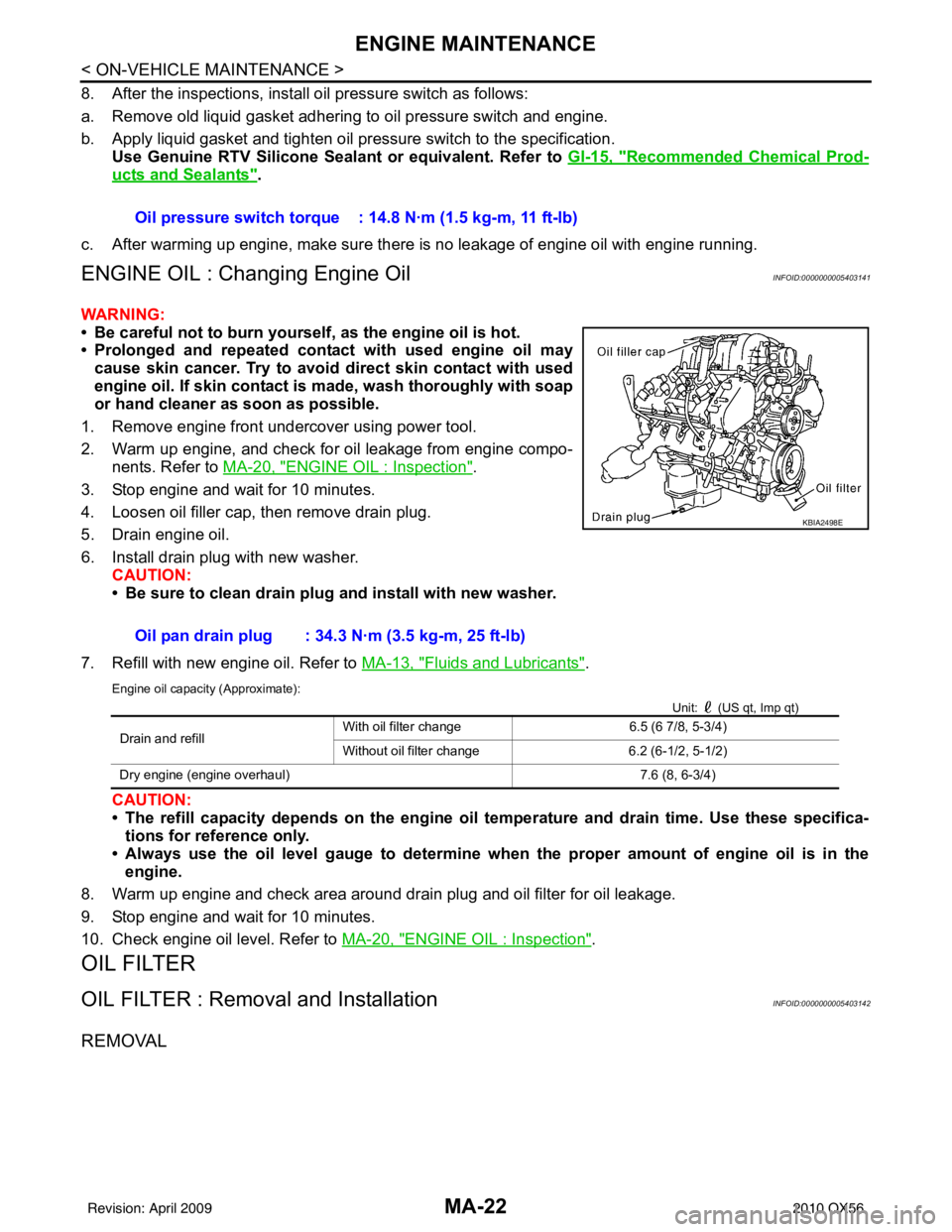
4. Loosen oil filler cap, then remove drain plug.
5. Drain engine oil.
6. Install drain plug with new washer. CAUTION:
• Be sure to clean drain plug and install with new washer.
7. Refill with new engine oil. Refer to MA-13, "
Fluids and Lubricants".
Engine oil capacity (Approximate):
Unit: (US qt, Imp qt)
CAUTION:
• The refill capacity depends on the engine oil temperature and drain time. Use these specifica-
tions for reference only.
• Always use the oil level gauge to determine when the proper amount of engine oil is in the engine.
8. Warm up engine and check area around drain plug and oil filter for oil leakage.
9. Stop engine and wait for 10 minutes.
10. Check engine oil level. Refer to MA-20, "
ENGINE OIL : Inspection".
OIL FILTER
OIL FILTER : Removal and InstallationINFOID:0000000005403142
REMOVAL
Oil pressure switch torque : 14.8 N·m (1.5 kg-m, 11 ft-lb)
Oil pan drain plug : 34.3 N·m (3.5 kg-m, 25 ft-lb)
KBIA2498E
Drain and refill With oil filter change
6.5 (6 7/8, 5-3/4)
Without oil filter change 6.2 (6-1/2, 5-1/2)
Dry engine (engine overhaul) 7.6 (8, 6-3/4)
Revision: April 20092010 QX56
Page 2727 of 4210
ENGINE MAINTENANCEMA-23
< ON-VEHICLE MAINTENANCE >
C
DE
F
G H
I
J
K L
M B
MA
N
O A
1. Drain the engine oil. Refer to
MA-22, "ENGINE OIL : Changing
Engine Oil".
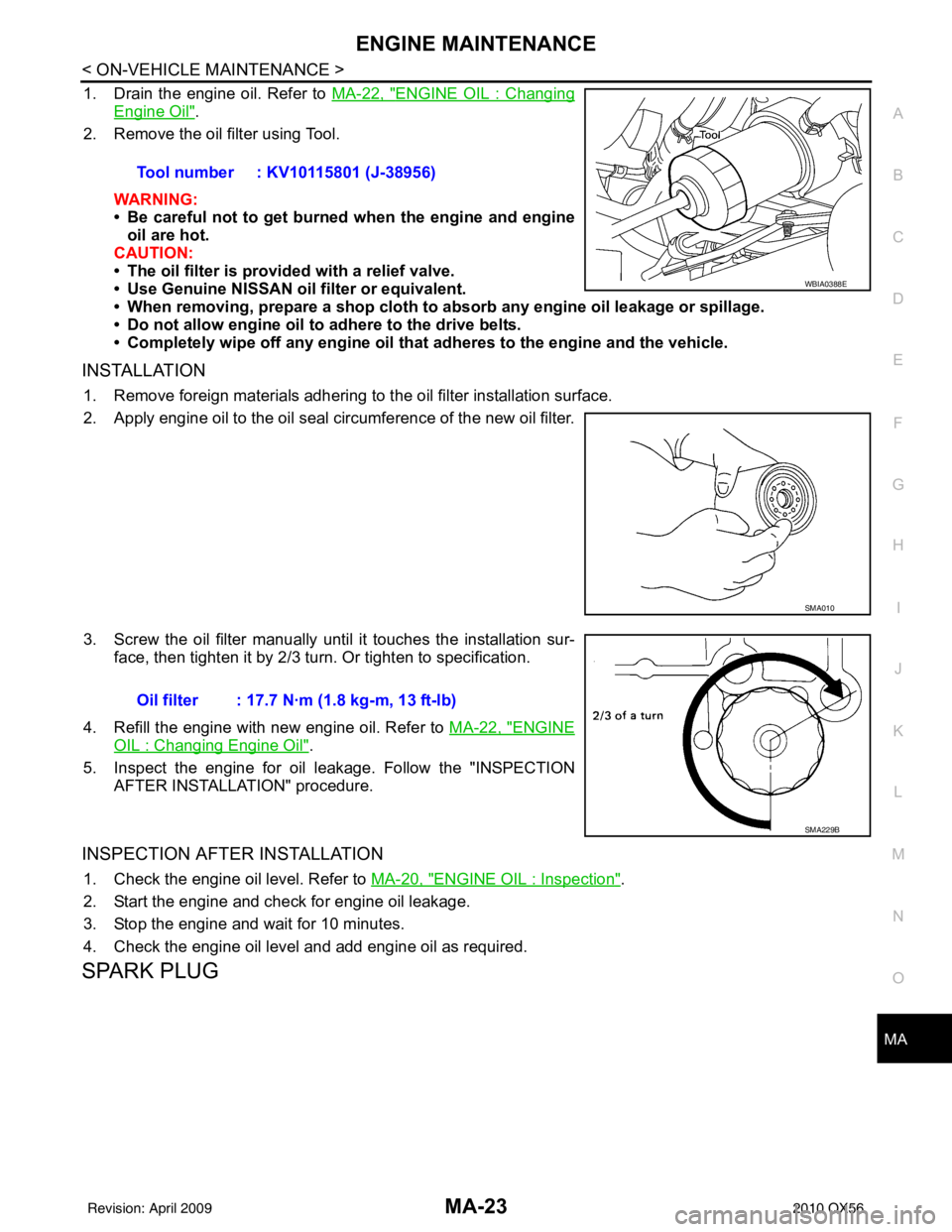
2. Remove the oil filter using Tool.
WARNING:
• Be careful not to get burned when the engine and engine
oil are hot.
CAUTION:
• The oil filter is provided with a relief valve.
• Use Genuine NISSAN oil filter or equivalent.
• When removing, prepare a shop cloth to ab sorb any engine oil leakage or spillage.
• Do not allow engine oil to adhere to the drive belts.
• Completely wipe off any engine oil that adheres to the engine and the vehicle.
INSTALLATION
1. Remove foreign materials adhering to the oil filter installation surface.
2. Apply engine oil to the oil seal circumference of the new oil filter.
3. Screw the oil filter manually until it touches the installation sur-
face, then tighten it by 2/3 turn. Or tighten to specification.
4. Refill the engine with new engine oil. Refer to MA-22, "
ENGINE
OIL : Changing Engine Oil".
5. Inspect the engine for oil leakage. Follow the "INSPECTION AFTER INSTALLATION" procedure.
INSPECTION AFTER INSTALLATION
1. Check the engine oil level. Refer to MA-20, "ENGINE OIL : Inspection".
2. Start the engine and check for engine oil leakage.
3. Stop the engine and wait for 10 minutes.
4. Check the engine oil level and add engine oil as required.
SPARK PLUG
Tool number : KV10115801 (J-38956)
WBIA0388E
SMA010
Oil filter : 17.7 N·m (1.8 kg-m, 13 ft-lb)
SMA229B
Revision: April 20092010 QX56
Page 2728 of 4210
MA-24
< ON-VEHICLE MAINTENANCE >
ENGINE MAINTENANCE
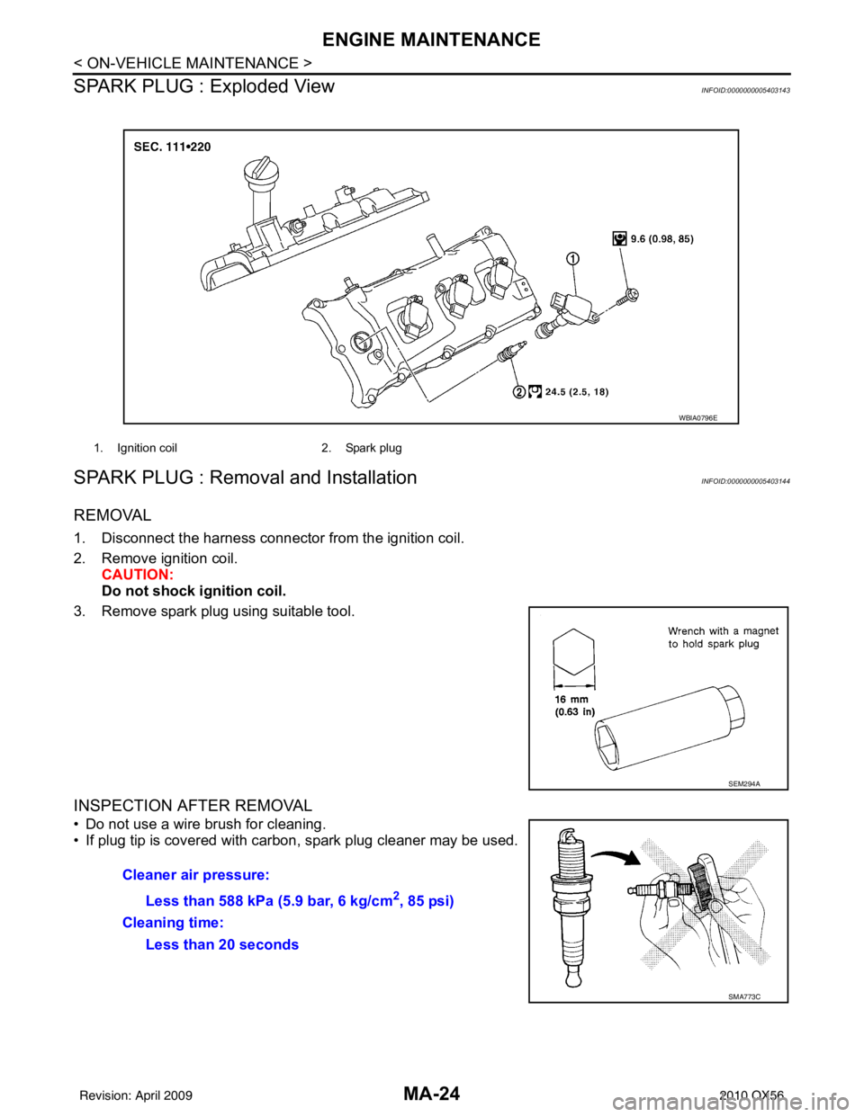
SPARK PLUG : Exploded View
INFOID:0000000005403143
SPARK PLUG : Removal and InstallationINFOID:0000000005403144
REMOVAL
1. Disconnect the harness connector from the ignition coil.
2. Remove ignition coil. CAUTION:
Do not shock ig nition coil.
3. Remove spark plug using suitable tool.
INSPECTION AFTER REMOVAL
• Do not use a wire brush for cleaning.
• If plug tip is covered with carbon, spark plug cleaner may be used.
1. Ignition coil 2. Spark plug
WBIA0796E
SEM294A
Cleaner air pressure:
Less than 588 kPa (5.9 bar, 6 kg/cm
2, 85 psi)
Cleaning time: Less than 20 seconds
SMA773C
Revision: April 20092010 QX56
Page 2733 of 4210
CHASSIS AND BODY MAINTENANCEMA-29
< ON-VEHICLE MAINTENANCE >
C
DE
F
G H
I
J
K L
M B
MA
N
O A
A/T FLUID : Changing the A/T Fluid (ATF)INFOID:0000000005403152
CAUTION:
If using the vehicle for towing, the A/T fluid must be replaced as specified. Refer to
MA-9, "
Introduc-
tion of Periodic Maintenance".
1. Drive the vehicle to warm up the A/T fluid to approximately 80 ° C (176 ° F).
2. Stop the engine.
3. Remove the A/T fluid level gauge.
4. Drain the A/T fluid from the drain plug hole, then install the drain plug with a new gasket. Refill the transmission with new A/T
fluid. Always refill with the same volume as the drained A/T fluid.
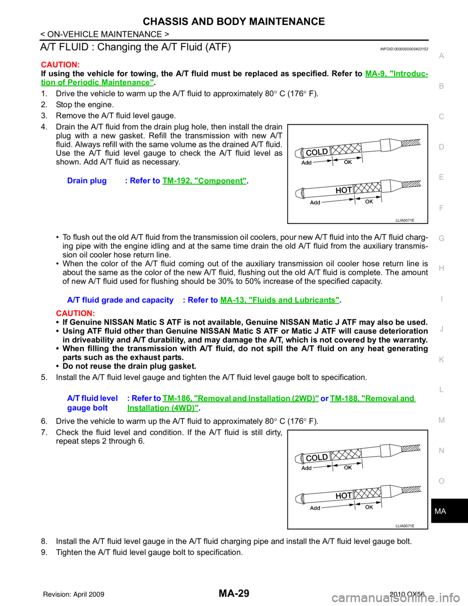
Use the A/T fluid level gauge to check the A/T fluid level as
shown. Add A/T fluid as necessary.
• To flush out the old A/T fluid from the transmission o il coolers, pour new A/T fluid into the A/T fluid charg-
ing pipe with the engine idling and at the same time drain the old A/T fluid from the auxiliary transmis-
sion oil cooler hose return line.
• When the color of the A/T fluid coming out of the aux iliary transmission oil cooler hose return line is
about the same as the color of the new A/T fluid, flushing out the old A/T fluid is complete. The amount
of new A/T fluid used for flushing should be 30% to 50% increase of the specified capacity.
CAUTION:
• If Genuine NISSAN Matic S ATF is not available, Genuine NISSAN Matic J ATF may also be used.
• Using ATF fluid other than Genuine NISSAN Matic S ATF or Matic J ATF will cause deterioration
in driveability and A/T durability, and may damage the A/T, which is not covered by the warranty.
• When filling the transmission with A/T fluid, do not spill the A/T fluid on any heat generating
parts such as the exhaust parts.
• Do not reuse the drain plug gasket.
5. Install the A/T fluid level gauge and tighten t he A/T fluid level gauge bolt to specification.
6. Drive the vehicle to warm up the A/T fluid to approximately 80 ° C (176 ° F).
7. Check the fluid level and condition. If the A/T fluid is still dirty, repeat steps 2 through 6.
8. Install the A/T fluid level gauge in the A/T fluid charging pipe and install the A/T fluid level gauge bolt.
9. Tighten the A/T fluid level gauge bolt to specification. Drain plug : Refer to
TM-192, "
Component".
LLIA0071E
A/T fluid grade and capacity : Refer to MA-13, "Fluids and Lubricants".
A/T fluid level
gauge bolt : Refer to
TM-186, "
Removal and Installation (2WD)" or TM-188, "Removal and
Installation (4WD)".
LLIA0071E
Revision: April 20092010 QX56
Page 2735 of 4210
CHASSIS AND BODY MAINTENANCEMA-31
< ON-VEHICLE MAINTENANCE >
C
DE
F
G H
I
J
K L
M B
MA
N
O A
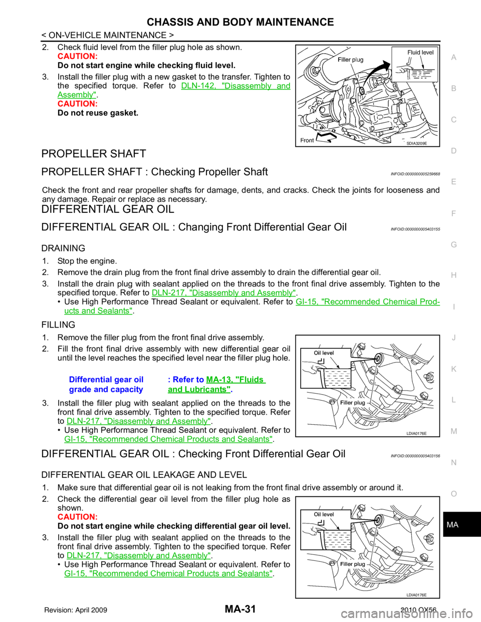
2. Check fluid level from the filler plug hole as shown.
CAUTION:
Do not start engine while checking fluid level.
3. Install the filler plug with a new gasket to the transfer. Tighten to the specified torque. Refer to DLN-142, "
Disassembly and
Assembly".
CAUTION:
Do not reuse gasket.
PROPELLER SHAFT
PROPELLER SHAFT : Checking Propeller ShaftINFOID:0000000005259668
Check the front and rear propeller shafts for damage, dents, and cracks. Check the joints for looseness and
any damage. Repair or replace as necessary.
DIFFERENTIAL GEAR OIL
DIFFERENTIAL GEAR OIL : Changing Front Differential Gear OilINFOID:0000000005403155
DRAINING
1. Stop the engine.
2. Remove the drain plug from the front final drive assembly to drain the differential gear oil.
3. Install the drain plug with sealant applied on the thr eads to the front final drive assembly. Tighten to the
specified torque. Refer to DLN-217, "
Disassembly and Assembly".
• Use High Performance Thread Sealant or equivalent. Refer to GI-15, "
Recommended Chemical Prod-
ucts and Sealants".
FILLING
1. Remove the filler plug from the front final drive assembly.
2. Fill the front final drive assembly with new differential gear oil
until the level reaches the specified level near the filler plug hole.
3. Install the filler plug with sealant applied on the threads to the front final drive assembly. Tighten to the specified torque. Refer
to DLN-217, "
Disassembly and Assembly".
• Use High Performance Thread Sealant or equivalent. Refer to GI-15, "
Recommended Chemical Products and Sealants".
DIFFERENTIAL GEAR OIL : Checking Front Differential Gear OilINFOID:0000000005403156
DIFFERENTIAL GEAR OIL LEAKAGE AND LEVEL
1. Make sure that differential gear oil is not leaking from the front final drive assembly or around it.
2. Check the differential gear oil level from the filler plug hole as
shown.
CAUTION:
Do not start engine while checki ng differential gear oil level.
3. Install the filler plug with sealant applied on the threads to the front final drive assembly. Tighten to the specified torque. Refer
to DLN-217, "
Disassembly and Assembly".
• Use High Performance Thread Sealant or equivalent. Refer to GI-15, "
Recommended Chemical Products and Sealants".
SDIA3209E
Differential gear oil
grade and capacity : Refer to
MA-13, "Fluids
and Lubricants".
LDIA0176E
LDIA0176E
Revision: April 20092010 QX56
Page 2736 of 4210
MA-32
< ON-VEHICLE MAINTENANCE >
CHASSIS AND BODY MAINTENANCE
DIFFERENTIAL GEAR OIL : Changi ng Rear Differential Gear Oil
INFOID:0000000005403157
DRAINING
1. Stop the engine.
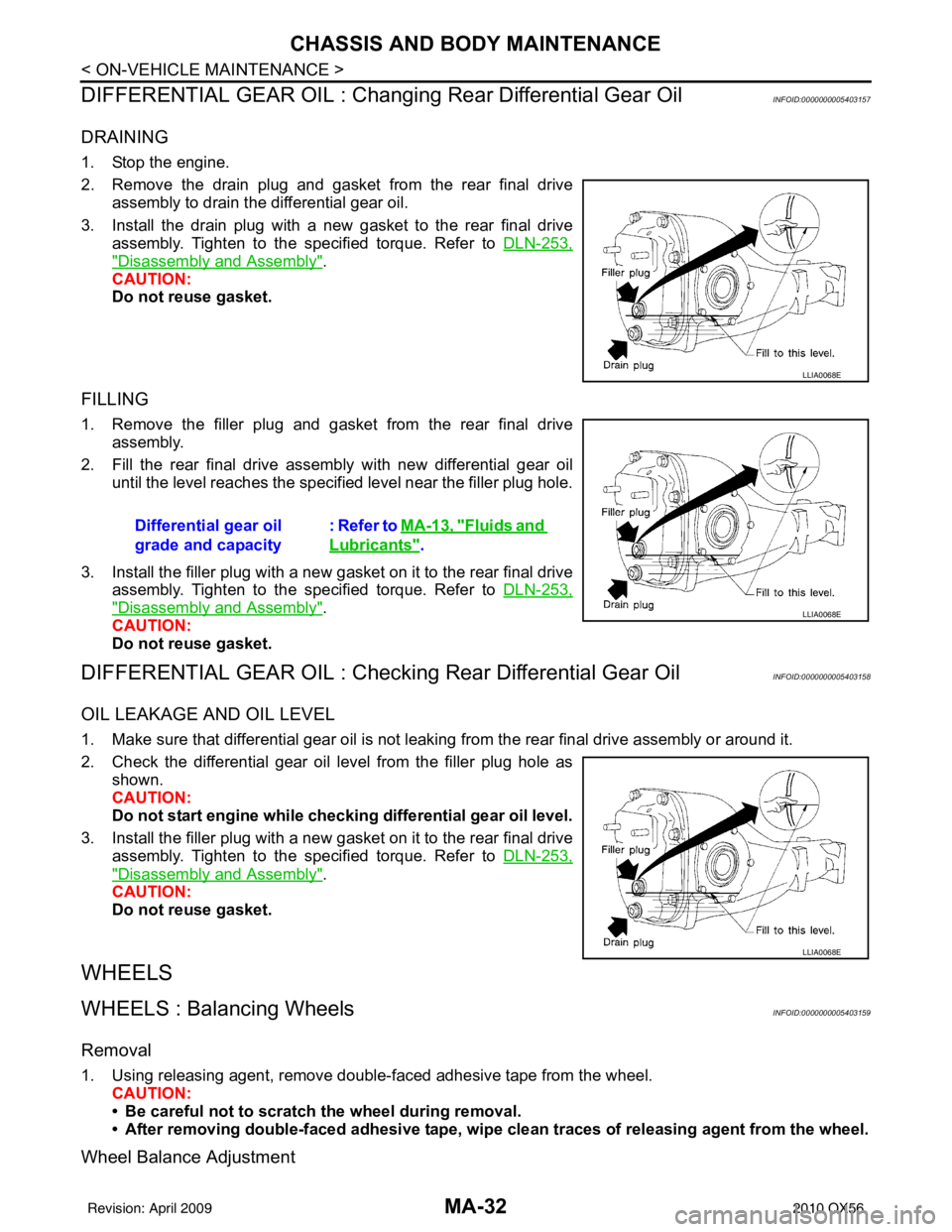
2. Remove the drain plug and gasket from the rear final drive
assembly to drain the differential gear oil.
3. Install the drain plug with a new gasket to the rear final drive assembly. Tighten to the specified torque. Refer to DLN-253,
"Disassembly and Assembly".
CAUTION:
Do not reuse gasket.
FILLING
1. Remove the filler plug and gasket from the rear final drive assembly.
2. Fill the rear final drive assembly with new differential gear oil until the level reaches the specified level near the filler plug hole.
3. Install the filler plug with a new gasket on it to the rear final drive assembly. Tighten to the specified torque. Refer to DLN-253,
"Disassembly and Assembly".
CAUTION:
Do not reuse gasket.
DIFFERENTIAL GEAR OIL : Checking Rear Differential Gear OilINFOID:0000000005403158
OIL LEAKAGE AND OIL LEVEL
1. Make sure that differential gear oil is not leaki ng from the rear final drive assembly or around it.
2. Check the differential gear oil level from the filler plug hole as shown.
CAUTION:
Do not start engine while checki ng differential gear oil level.
3. Install the filler plug with a new gasket on it to the rear final drive assembly. Tighten to the specified torque. Refer to DLN-253,
"Disassembly and Assembly".
CAUTION:
Do not reuse gasket.
WHEELS
WHEELS : Balancing WheelsINFOID:0000000005403159
Removal
1. Using releasing agent, remove double-faced adhesive tape from the wheel. CAUTION:
• Be careful not to scratch the wheel during removal.
• After removing double-faced adh esive tape, wipe clean traces of releasing agent from the wheel.
Wheel Balance Adjustment
LLIA0068E
Differential gear oil
grade and capacity: Refer to MA-13, "Fluids and
Lubricants".
LLIA0068E
LLIA0068E
Revision: April 20092010 QX56
Page 2741 of 4210
CHASSIS AND BODY MAINTENANCEMA-37
< ON-VEHICLE MAINTENANCE >
C
DE
F
G H
I
J
K L
M B
MA
N
O A
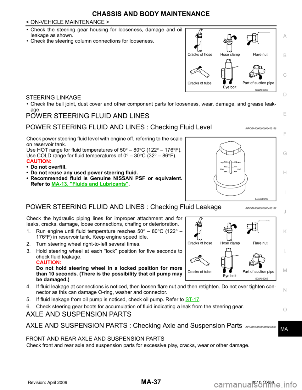
• Check the steering gear housing for looseness, damage and oil
leakage as shown.
• Check the steering column connections for looseness.
STEERING LINKAGE
• Check the ball joint, dust cover and other component parts for looseness, wear, damage, and grease leak-
age.
POWER STEERING FLUID AND LINES
POWER STEERING FLUID AND LINE S : Checking Fluid LevelINFOID:0000000005403166
Check power steering fluid level with engine off, referring to the scale
on reservoir tank.
Use HOT range for fluid temperatures of 50 ° – 80 °C (122 ° – 176 °F).
Use COLD range for fluid temperatures of 0 ° – 30 °C (32° – 86°F).
CAUTION:
• Do not overfill.
• Do not reuse any used power steering fluid.
• Recommended fluid is Genuine NISSAN PSF or equivalent.
Refer to MA-13, "
Fluids and Lubricants".
POWER STEERING FLUID AND LINES : Checking Fluid LeakageINFOID:0000000005403167
Check the hydraulic piping lines for improper attachment and for
leaks, cracks, damage, loose connec tions, chafing or deterioration.
1. Run engine until fluid temperature reaches 50 ° – 80° C (122° –
176° F) in reservoir tank. Keep engine speed idle.
2. Turn steering wheel right-to-left several times.
3. Hold steering wheel at each “lock” position for five seconds to check fluid leakage.
CAUTION:
Do not hold steering wheel in a locked position for more
than 10 seconds. (There is the possibility that oil pump may
be damaged.)
4. If fluid leakage at connections is noticed, then loosen flare nut and then retighten. Do not over tighten con- nector as this can damage O-ring, washer and connector.
5. If fluid leakage from oil pump is noticed, check oil pump. Refer to ST-17
.
6. Check steering gear boots for accumulation of fluid indicating a leak from the steering gear.
AXLE AND SUSPENSION PARTS
AXLE AND SUSPENSION PARTS : Chec king Axle and Suspension PartsINFOID:0000000005259684
FRONT AND REAR AXLE AND SUSPENSION PARTS
Check front and rear axle and suspension parts for excessive play, cracks, wear or other damage.
SGIA0506E
LGIA0021E
SGIA0506E
Revision: April 20092010 QX56