2010 INFINITI QX56 service indicator
[x] Cancel search: service indicatorPage 1610 of 4210
![INFINITI QX56 2010 Factory Service Manual P0455 EVAP CONTROL SYSTEMEC-257
< COMPONENT DIAGNOSIS > [VK56DE]
C
D
E
F
G H
I
J
K L
M A
EC
NP
O
To locate the EVAP leak, install EVAP service port adapter and pres-
sure pump to EVAP service port sec INFINITI QX56 2010 Factory Service Manual P0455 EVAP CONTROL SYSTEMEC-257
< COMPONENT DIAGNOSIS > [VK56DE]
C
D
E
F
G H
I
J
K L
M A
EC
NP
O
To locate the EVAP leak, install EVAP service port adapter and pres-
sure pump to EVAP service port sec](/manual-img/42/57032/w960_57032-1609.png)
P0455 EVAP CONTROL SYSTEMEC-257
< COMPONENT DIAGNOSIS > [VK56DE]
C
D
E
F
G H
I
J
K L
M A
EC
NP
O
To locate the EVAP leak, install EVAP service port adapter and pres-
sure pump to EVAP service port securely.
NOTE:
Improper installation of the EV
AP service port adapter to the
EVAP service port may cause leaking.
With CONSULT-III>>GO TO 9.
Without CONSULT-III>>GO TO 10.
9.CHECK FOR EVAP LEAK
With CONSULT-II I
1. Turn ignition switch ON.
2. Select “EVAP SYSTEM CLOSE” of “WORK SUPPORT” mode with CONSULT-III.
3. Touch “START” and apply pressure into the EVAP line until the pressure indicator reaches the middle of the bar graph.
CAUTION:
• Do not use compressed air or a high pressure pump.
• Do not exceed 4.12 kPa (0.042 kg/cm
2, 0.6 psi) of pressure in the system.
4. Using EVAP leak detector, locate the EVAP leak. For the leak detector, refer to the instruction manual for more details.
Refer to EC-37, "
Description".
OK or NG
OK >> GO TO 11.
NG >> Repair or replace.
10.CHECK FOR EVAP LEAK
Without CONSULT-III
1. Turn ignition switch OFF.
BBIA0366E
SEF916U
SEF200U
Revision: April 20092010 QX56
Page 1617 of 4210
![INFINITI QX56 2010 Factory Service Manual EC-264
< COMPONENT DIAGNOSIS >[VK56DE]
P0456 EVAP CONTROL SYSTEM
3.CHECK FUEL FILLER CAP FUNCTION
Check for air releasing sound while opening the fuel filler cap.
OK or NG
OK >> GO TO 5.
NG >> GO TO 4 INFINITI QX56 2010 Factory Service Manual EC-264
< COMPONENT DIAGNOSIS >[VK56DE]
P0456 EVAP CONTROL SYSTEM
3.CHECK FUEL FILLER CAP FUNCTION
Check for air releasing sound while opening the fuel filler cap.
OK or NG
OK >> GO TO 5.
NG >> GO TO 4](/manual-img/42/57032/w960_57032-1616.png)
EC-264
< COMPONENT DIAGNOSIS >[VK56DE]
P0456 EVAP CONTROL SYSTEM
3.CHECK FUEL FILLER CAP FUNCTION
Check for air releasing sound while opening the fuel filler cap.
OK or NG
OK >> GO TO 5.
NG >> GO TO 4.
4.CHECK FUEL TANK VACUUM RELIEF VALVE
Refer to EC-268, "
Component Inspection".
OK or NG
OK >> GO TO 5.
NG >> Replace fuel filler cap with a genuine one.
5.INSTALL THE PRESSURE PUMP
To locate the EVAP leak, install EVAP service port adapter and pres-
sure pump to EVAP service port securely.
NOTE:
Improper installation of the EV AP service port adapter to the
EVAP service port may cause leaking.
With CONSULT-III>>GO TO 6.
Without CONSULT-III>>GO TO 7.
6.CHECK FOR EVAP LEAK
With CONSULT-III
1. Turn ignition switch ON.
2. Select “EVAP SYSTEM CLOSE” of “WORK SUPPORT” mode with CONSULT-III.
3. Touch “START” and apply pressure into the EVAP line until the pressure indicator reaches the middle of
the bar graph.
CAUTION:
• Do not use compressed air or a high pressure pump.
• Do not exceed 4.12 kPa (0.042 kg/cm
2, 0.6 psi) of pressure in the system.
BBIA0366E
SEF916U
Revision: April 20092010 QX56
Page 1829 of 4210
![INFINITI QX56 2010 Factory Service Manual EC-476
< ECU DIAGNOSIS >[VK56DE]
ECM
1. If the ignition switch stays ON after repair work, be sure to turn ignition switch OFF once. Wait at least 10
seconds and then turn it ON (engine stopped) again INFINITI QX56 2010 Factory Service Manual EC-476
< ECU DIAGNOSIS >[VK56DE]
ECM
1. If the ignition switch stays ON after repair work, be sure to turn ignition switch OFF once. Wait at least 10
seconds and then turn it ON (engine stopped) again](/manual-img/42/57032/w960_57032-1828.png)
EC-476
< ECU DIAGNOSIS >[VK56DE]
ECM
1. If the ignition switch stays ON after repair work, be sure to turn ignition switch OFF once. Wait at least 10
seconds and then turn it ON (engine stopped) again.
2. Perform TM-30, "
OBD-II Diagnostic Trouble Code (DTC)". (The DTC in TCM will be erased)
3. Select Service $04 with GST (Generic Scan Tool).
No Tools
NOTE:
If the DTC is not for AT related items (see EC-459, "
DTC Index"), skip step 2.
1. If the ignition switch stays ON after repair work, be sure to turn ignition switch OFF once.
Wait at least 10 seconds and then turn it ON (engine stopped) again.
2. Perform TM-30, "
OBD-II Diagnostic Trouble Code (DTC)". (The DTC in the TCM will be erased.)
3. Change the diagnostic test mode from Mode II to Mode I by depressing the accelerator pedal. Refer to
EC-55, "
Malfunction Indicator Lamp (MIL)".
• If the battery is disconnected, the emission-related diagnostic information will be lost within 24
hours.
• The following data are cleared when the ECM memory is erased.
- Diagnostic trouble codes
- 1st trip diagnostic trouble codes
- Freeze frame data
- 1st trip freeze frame data
- System readiness test (SRT) codes
- Test values
Actual work procedures are explained using a DTC as an example. Be careful so that not only the DTC, but all
of the data listed above, are cleared from the ECM memory during work procedures.
Revision: April 20092010 QX56
Page 1835 of 4210
![INFINITI QX56 2010 Factory Service Manual EC-482
< PRECAUTION >[VK56DE]
PRECAUTIONS
PRECAUTION
PRECAUTIONS
Precaution for Supplemental Restraint Syst
em (SRS) "AIR BAG" and "SEAT BELT
PRE-TENSIONER"
INFOID:0000000005149502
The Supplemental R INFINITI QX56 2010 Factory Service Manual EC-482
< PRECAUTION >[VK56DE]
PRECAUTIONS
PRECAUTION
PRECAUTIONS
Precaution for Supplemental Restraint Syst
em (SRS) "AIR BAG" and "SEAT BELT
PRE-TENSIONER"
INFOID:0000000005149502
The Supplemental R](/manual-img/42/57032/w960_57032-1834.png)
EC-482
< PRECAUTION >[VK56DE]
PRECAUTIONS
PRECAUTION
PRECAUTIONS
Precaution for Supplemental Restraint Syst
em (SRS) "AIR BAG" and "SEAT BELT
PRE-TENSIONER"
INFOID:0000000005149502
The Supplemental Restraint System such as “A IR BAG” and “SEAT BELT PRE-TENSIONER”, used along
with a front seat belt, helps to reduce the risk or severity of injury to the driver and front passenger for certain
types of collision. This system includes seat belt switch inputs and dual stage front air bag modules. The SRS
system uses the seat belt switches to determine the front air bag deployment, and may only deploy one front
air bag, depending on the severity of a collision and w hether the front occupants are belted or unbelted.
Information necessary to service the system safely is included in the SRS and SB section of this Service Man-
ual.
WARNING:
• To avoid rendering the SRS inopera tive, which could increase the risk of personal injury or death in
the event of a collision which would result in air bag inflation, all maintenance must be performed by
an authorized NISSAN/INFINITI dealer.
• Improper maintenance, including in correct removal and installation of the SRS, can lead to personal
injury caused by unintent ional activation of the system. For re moval of Spiral Cable and Air Bag
Module, see the SRS section.
• Do not use electrical test equipmen t on any circuit related to the SRS unless instructed to in this
Service Manual. SRS wiring harn esses can be identified by yellow and/or orange harnesses or har-
ness connectors.
On Board Diagnosis (OBD) S ystem of Engine and A/TINFOID:0000000005149503
The ECM has an on board diagnostic system. It will light up the malfunction indicator lamp (MIL) to warn the
driver of a malfunction causing emission deterioration.
CAUTION:
• Be sure to turn the ignition switch OFF and disconnect the negative battery cable before any repair
or inspection work. The open/short circuit of re lated switches, sensors, solenoid valves, etc. will
cause the MIL to light up.
• Be sure to connect and lock the connectors secure ly after work. A loose (unlocked) connector will
cause the MIL to light up due to the open circuit. (Be sure the connector is free from water, grease,
dirt, bent terminals, etc.)
• Certain systems and components, especially those related to OBD, may use a new style slide-lock-
ing type harness connector. For descrip tion and how to disconnect, refer to PG-64
.
• Be sure to route and secure the harnesses properly after work. The interference of the harness with
a bracket, etc. may cause the MIL to li ght up due to the short circuit.
• Be sure to connect rubber tubes properly afte r work. A misconnected or disconnected rubber tube
may cause the MIL to light up due to the malfunction of the EVAP system or fuel injection system,
etc.
• Be sure to erase the unnecessary malfunction info rmation (repairs completed) from the ECM and
TCM (Transmission control module) before returning the vehicle to the customer.
PrecautionINFOID:0000000005149504
•Always use a 12 volt battery as power source.
• Do not attempt to disconnect battery cables while engine is
running.
• Before connecting or disconnecting the ECM harness con-
nector, turn ignition switch OFF and disconnect negative bat-
tery cable. Failure to do so may damage the ECM because
battery voltage is applied to ECM even if ignition switch is
turned OFF.
• Before removing parts, turn ig nition switch OFF and then dis-
connect negative battery cable.
SEF289H
Revision: April 20092010 QX56
Page 1844 of 4210
![INFINITI QX56 2010 Factory Service Manual EVAP LEAK CHECKEC-491
< ON-VEHICLE MAINTENANCE > [VK56DE]
C
D
E
F
G H
I
J
K L
M A
EC
NP
O
EVAP LEAK CHECK
How to Detect Fuel Vapor LeakageINFOID:0000000005149508
CAUTION:
• Never use compressed air INFINITI QX56 2010 Factory Service Manual EVAP LEAK CHECKEC-491
< ON-VEHICLE MAINTENANCE > [VK56DE]
C
D
E
F
G H
I
J
K L
M A
EC
NP
O
EVAP LEAK CHECK
How to Detect Fuel Vapor LeakageINFOID:0000000005149508
CAUTION:
• Never use compressed air](/manual-img/42/57032/w960_57032-1843.png)
EVAP LEAK CHECKEC-491
< ON-VEHICLE MAINTENANCE > [VK56DE]
C
D
E
F
G H
I
J
K L
M A
EC
NP
O
EVAP LEAK CHECK
How to Detect Fuel Vapor LeakageINFOID:0000000005149508
CAUTION:
• Never use compressed air
or a high pressure pump.
• Do not exceed 4.12 kPa (0.042 kg/cm
2, 0.6 psi) of pressure in EVAP system.
NOTE:
• Do not start engine.
• Improper installation of EVAP service port adapter to the EVAP service port may cause a leak.
WITH CONSULT-IIl
1. Attach the EVAP service port adapter securely to the EVAP service port.
2. Also attach the pressure pump and hose to the EVAP service port adapter.
3. Turn ignition switch ON.
4. Select the “EVAP SYSTEM CLOSE” of “WORK SUPPORT MODE” with CONSULT-IIl.
5. Touch “START”. A bar graph (Pressure indicating display) will appear on the screen.
6. Apply positive pressure to the EVAP system until the pressure indicator reaches the middle of the bar graph.
7. Remove EVAP service port adapter and hose with pressure pump.
8. Locate the leak using a leak detector. Refer to EC-37, "
Descrip-
tion".
WITHOUT CONSULT-IIl
1. Attach the EVAP service port adapter securely to the EVAP ser-
vice port.
2. Also attach the pressure pump with pressure gauge to the EVAP service port adapter.
SEF200U
BBIA0366E
SEF462UA
Revision: April 20092010 QX56
Page 1960 of 4210

SERVICE DATA AND SPECIFICATIONS (SDS)EM-109
< SERVICE DATA AND SPECIFICATIONS (SDS)
C
DE
F
G H
I
J
K L
M A
EM
NP
O
Unit: mm (in)
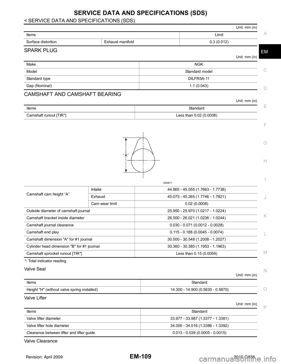
SPARK PLUG
Unit: mm (in)
CAMSHAFT AND CAMSHAFT BEARING
Unit: mm (in)
*: Total indicator reading
Valve Seal
Unit: mm (in)
Valve Lifter
Unit: mm (in)
Valve Clearance
Items
Limit
Surface distortion Exhaust manifold 0.3 (0.012)
Make NGK
Model Standard model
Standard type DILFR5A-11
Gap (Nominal) 1.1 (0.043)
ItemsStandard
Camshaft runout [TIR*] Less than 0.02 (0.0008)
Camshaft cam height “A” Intake
44.865 - 45.055 (1.7663 - 1.7738)
Exhaust 45.075 - 45.265 (1.7746 - 1.7821)
Cam wear limit 0.02 (0.0008)
Outside diameter of camshaft journal 25.950 - 25.970 (1.0217 - 1.0224)
Camshaft bracket inside diameter 26.000 - 26.021 (1.0236 - 1.0244)
Camshaft journal clearance 0.030 - 0.071 (0.0012 - 0.0028)
Camshaft end play 0.115 - 0.188 (0.0045 - 0.0074)
Camshaft dimension "A" for #1 journal 30.500 - 30.548 (1.2008 - 1.2027)
Cylinder head dimension "B" for #1 journal 30.360 - 30.385 (1.1953 - 1.1963)
Camshaft sprocket runout [TIR*] Less than 0.15 (0.0059)
SEM671
Items Standard
Height "H" (without valve spring installed) 14.300 - 14.900 (0.5630 - 0.5870)
Items Standard
Valve lifter diameter 33.977 - 33.987 (1.3377 - 1.3381)
Valve lifter hole diameter 34.000 - 34.016 (1.3386 - 1.3392)
Clearance between lifter and lifter guide 0.013 - 0.039 (0.0005 - 0.0015)
Revision: April 20092010 QX56
Page 1967 of 4210

EM-116
< SERVICE DATA AND SPECIFICATIONS (SDS)
SERVICE DATA AND SPECIFICATIONS (SDS)
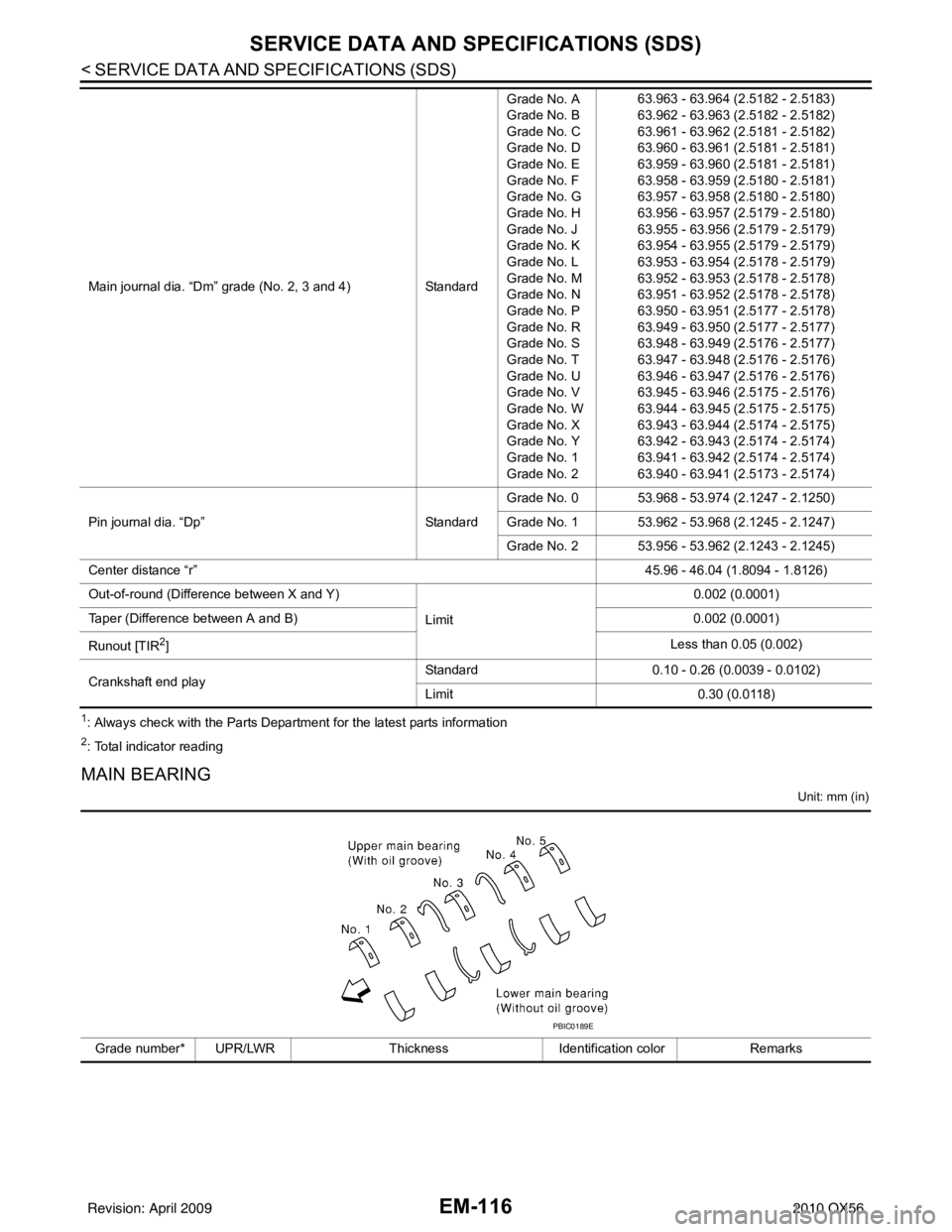
1: Always check with the Parts Department for the latest parts information
2: Total indicator reading
MAIN BEARING
Unit: mm (in)
Main journal dia. “Dm” grade (No. 2, 3 and 4)StandardGrade No. A
Grade No. B
Grade No. C
Grade No. D
Grade No. E
Grade No. F
Grade No. G
Grade No. H
Grade No. J
Grade No. K
Grade No. L
Grade No. M
Grade No. N
Grade No. P
Grade No. R
Grade No. S
Grade No. T
Grade No. U
Grade No. V
Grade No. W
Grade No. X
Grade No. Y
Grade No. 1
Grade No. 2 63.963 - 63.964 (2.5182 - 2.5183)
63.962 - 63.963 (2.5182 - 2.5182)
63.961 - 63.962 (2.5181 - 2.5182)
63.960 - 63.961 (2.5181 - 2.5181)
63.959 - 63.960 (2.5181 - 2.5181)
63.958 - 63.959 (2.5180 - 2.5181)
63.957 - 63.958 (2.5180 - 2.5180)
63.956 - 63.957 (2.5179 - 2.5180)
63.955 - 63.956 (2.5179 - 2.5179)
63.954 - 63.955 (2.5179 - 2.5179)
63.953 - 63.954 (2.5178 - 2.5179)
63.952 - 63.953 (2.5178 - 2.5178)
63.951 - 63.952 (2.5178 - 2.5178)
63.950 - 63.951 (2.5177 - 2.5178)
63.949 - 63.950 (2.5177 - 2.5177)
63.948 - 63.949 (2.5176 - 2.5177)
63.947 - 63.948 (2.5176 - 2.5176)
63.946 - 63.947 (2.5176 - 2.5176)
63.945 - 63.946 (2.5175 - 2.5176)
63.944 - 63.945 (2.5175 - 2.5175)
63.943 - 63.944 (2.5174 - 2.5175)
63.942 - 63.943 (2.5174 - 2.5174)
63.941 - 63.942 (2.5174 - 2.5174)
63.940 - 63.941 (2.5173 - 2.5174)
Pin journal dia. “Dp” StandardGrade No. 0 53.968 - 53.974 (2.1247 - 2.1250)
Grade No. 1 53.962 - 53.968 (2.1245 - 2.1247)
Grade No. 2 53.956 - 53.962 (2.1243 - 2.1245)
Center distance “r” 45.96 - 46.04 (1.8094 - 1.8126)
Out-of-round (Difference between X and Y)
Limit0.002 (0.0001)
Taper (Difference between A and B) 0.002 (0.0001)
Runout [TIR
2] Less than 0.05 (0.002)
Crankshaft end play Standard
0.10 - 0.26 (0.0039 - 0.0102)
Limit 0.30 (0.0118)
Grade number* UPR/LWR Thickness Identification color Remarks
PBIC0189E
Revision: April 20092010 QX56
Page 2206 of 4210

ON-VEHICLE SERVICEFSU-7
< ON-VEHICLE MAINTENANCE >
C
DF
G H
I
J
K L
M A
B
FSU
N
O P
2. Make sure the alignment machine is properly calibrated. • Your alignment machine should be regularly calibrated in order to give correct information.
• Check with the manufacturer of your specific a lignment machine for their recommended Service/Cali-
bration Schedule.
THE ALIGNMENT PROCESS
IMPORTANT: Use only the alignment specifications listed in this Service Manual. Refer to FSU-23, "Wheel
Alignment (Unladen*1)" .
1. When displaying the alignment settings, many alignm ent machines use “indicators”: (Green/red, plus or
minus, Go/No Go). Do NOT use these indicators.
• The alignment specifications programmed into your alignment machine that operate these indicators may not be correct.
• This may result in an ERROR.
2. Some newer alignment machines are equipped with an optional “Rolling Compensation” method to “com-
pensate” the sensors (alignment targets or head units). Do NOT use this “Rolling Compensation”
method.
• Use the “Jacking Compensation” method. After installing the alignment targets or head units, raise the vehicle and rotate the wheels 1/2 turn both ways.
• See Instructions in the alignment machine you are using for more information.
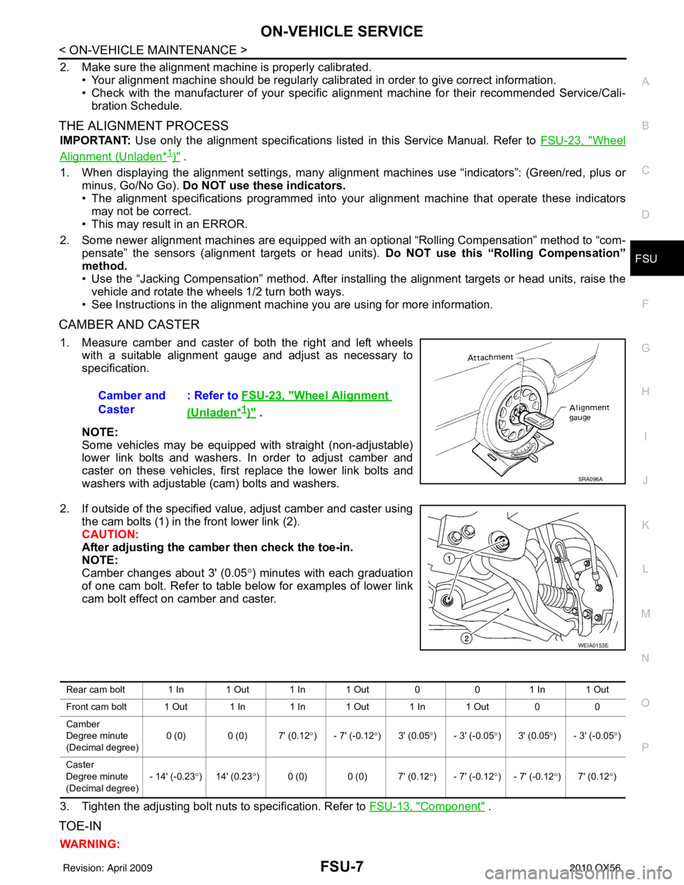
CAMBER AND CASTER
1. Measure camber and caster of both the right and left wheels with a suitable alignment gauge and adjust as necessary to
specification.
NOTE:
Some vehicles may be equipped with straight (non-adjustable)
lower link bolts and washers. In order to adjust camber and
caster on these vehicles, first replace the lower link bolts and
washers with adjustable (cam) bolts and washers.
2. If outside of the specified value, adjust camber and caster using the cam bolts (1) in the front lower link (2).
CAUTION:
After adjusting the camber then check the toe-in.
NOTE:
Camber changes about 3' (0.05 °) minutes with each graduation
of one cam bolt. Refer to table below for examples of lower link
cam bolt effect on camber and caster.
3. Tighten the adjusting bolt nuts to specification. Refer to FSU-13, "
Component" .
TOE-IN
WARNING:Camber and
Caster
: Refer to
FSU-23, "
Wheel Alignment
(Unladen*1)" .
SRA096A
WEIA0153E
Rear cam bolt 1 In 1 Out 1 In 1 Out 0 01 In 1 Out
Front cam bolt 1 Out 1 In 1 In 1 Out 1 In 1 Out 0 0
Camber
Degree minute
(Decimal degree) 0 (0) 0 (0) 7' (0.12
°) - 7' (-0.12 °)3' (0.05 °) - 3' (-0.05 °)3' (0.05 °) - 3' (-0.05 °)
Caster
Degree minute
(Decimal degree) - 14' (-0.23
°)14' (0.23 °) 0 (0) 0 (0) 7' (0.12° ) - 7' (-0.12°) - 7' (-0.12 °)7' (0.12 °)
Revision: April 20092010 QX56