2010 INFINITI QX56 oil capacity
[x] Cancel search: oil capacityPage 1931 of 4210
EM-80
< REMOVAL AND INSTALLATION >
ENGINE ASSEMBLY
• Before and during lifting, always check if any harnesses are left connected.
33. Remove the parts that may restrict installation of the engine to the engine stand. NOTE:
This procedure is described assuming that you use an engine stand mounting to the surface to which the
transmission mounts.
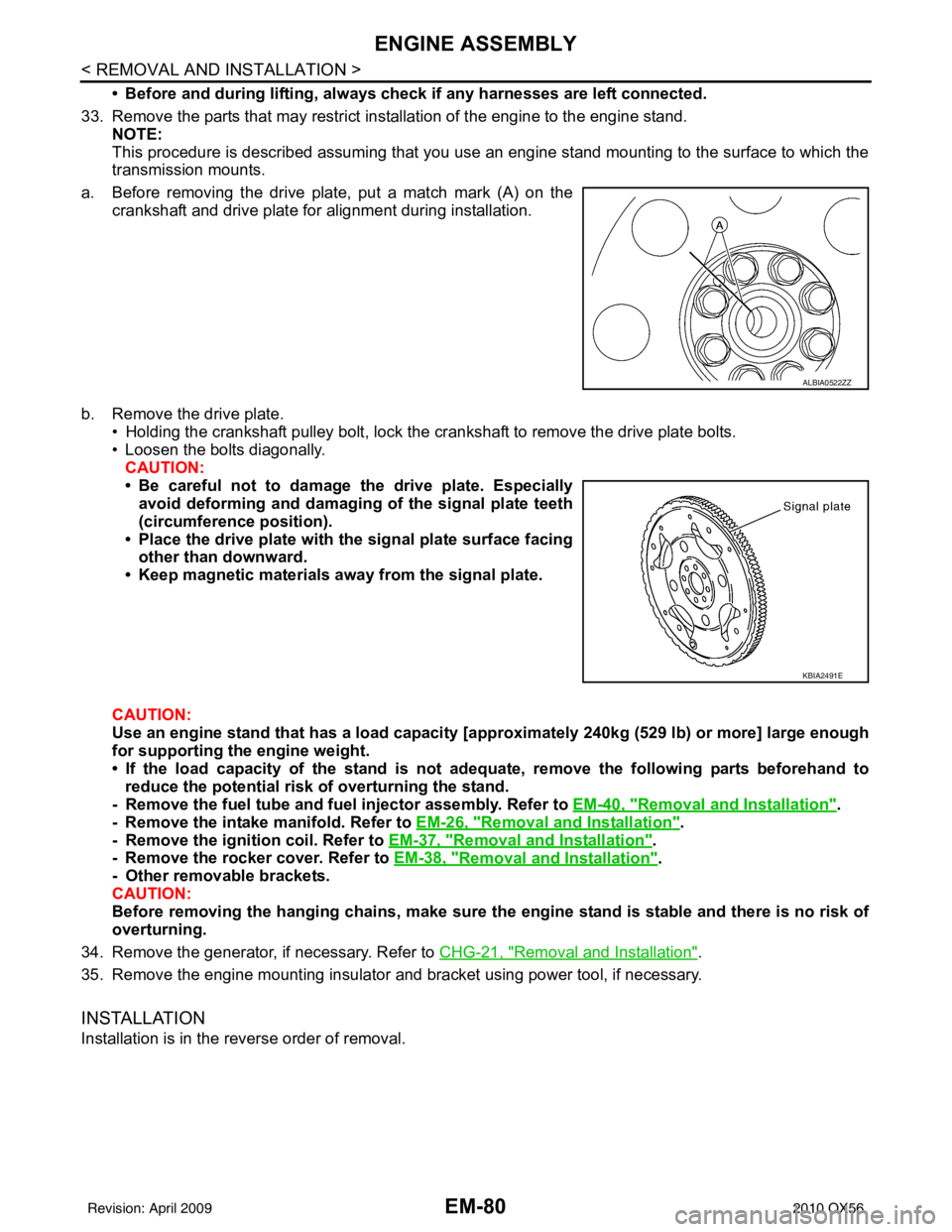
a. Before removing the drive plate, put a match mark (A) on the crankshaft and drive plate for alignment during installation.
b. Remove the drive plate. • Holding the crankshaft pulley bolt, lock the crankshaft to remove the drive plate bolts.
• Loosen the bolts diagonally.CAUTION:
• Be careful not to damage the drive plate. Especiallyavoid deforming and damaging of the signal plate teeth
(circumference position).
• Place the drive plate with th e signal plate surface facing
other than downward.
• Keep magnetic materials away from the signal plate.
CAUTION:
Use an engine stand that has a load capacity [a pproximately 240kg (529 lb) or more] large enough
for supporting the engine weight.
• If the load capacity of the stand is not adeq uate, remove the following parts beforehand to
reduce the potential risk of overturning the stand.
- Remove the fuel tube and fuel injector assembly. Refer to EM-40, "
Removal and Installation".
- Remove the intake manifold. Refer to EM-26, "
Removal and Installation".
- Remove the ignition coil. Refer to EM-37, "
Removal and Installation".
- Remove the rocker cover. Refer to EM-38, "
Removal and Installation".
- Other removable brackets.
CAUTION:
Before removing the hanging chains, make sure th e engine stand is stable and there is no risk of
overturning.
34. Remove the generator, if necessary. Refer to CHG-21, "
Removal and Installation".
35. Remove the engine mounting insulator and bracket using power tool, if necessary.
INSTALLATION
Installation is in the reverse order of removal.
ALBIA0522ZZ
KBIA2491E
Revision: April 20092010 QX56
Page 2308 of 4210
HA-16
< PREPARATION >
PREPARATION
Commercial Service Tool
INFOID:0000000005147641
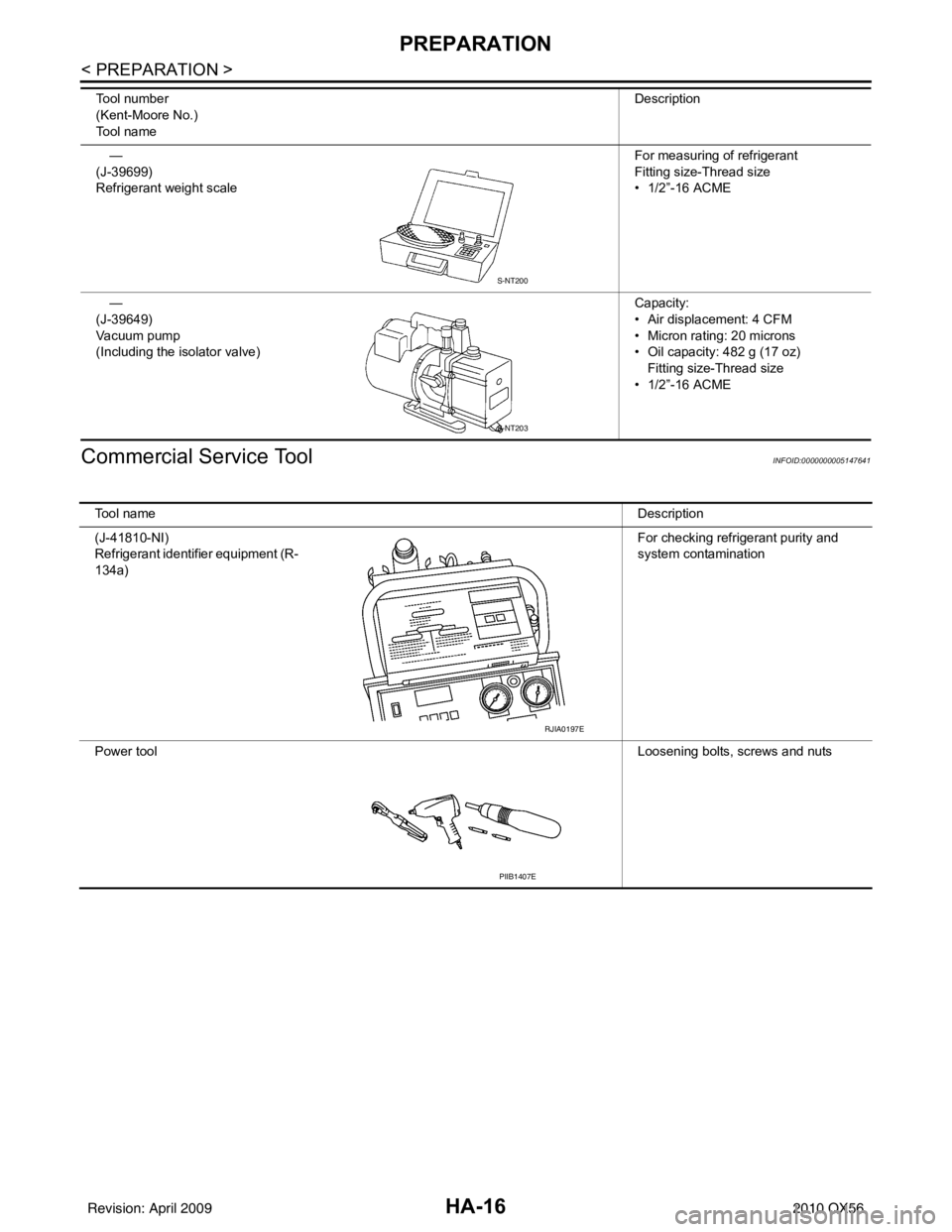
—
(J-39699)
Refrigerant weight scale For measuring of refrigerant
Fitting size-Thread size
• 1/2”-16 ACME
—
(J-39649)
Vacuum pump
(Including the isolator valve) Capacity:
• Air displacement: 4 CFM
• Micron rating: 20 microns
• Oil capacity: 482 g (17 oz)
Fitting size-Thread size
• 1/2”-16 ACME
Tool number
(Kent-Moore No.)
Tool name
Description
S-NT200
S-NT203
Tool name
Description
(J-41810-NI)
Refrigerant identifier equipment (R-
134a) For checking refrigerant purity and
system contamination
Power tool Loosening bolts, screws and nuts
RJIA0197E
PIIB1407E
Revision: April 20092010 QX56
Page 2340 of 4210
HA-48
< SERVICE DATA AND SPECIFICATIONS (SDS)
SERVICE DATA AND SPECIFICATIONS (SDS)
SERVICE DATA AND SPECIFICATIONS (SDS)
SERVICE DATA AND SPECIFICATIONS (SDS)
Service Data and Specification (SDS)INFOID:0000000005147667
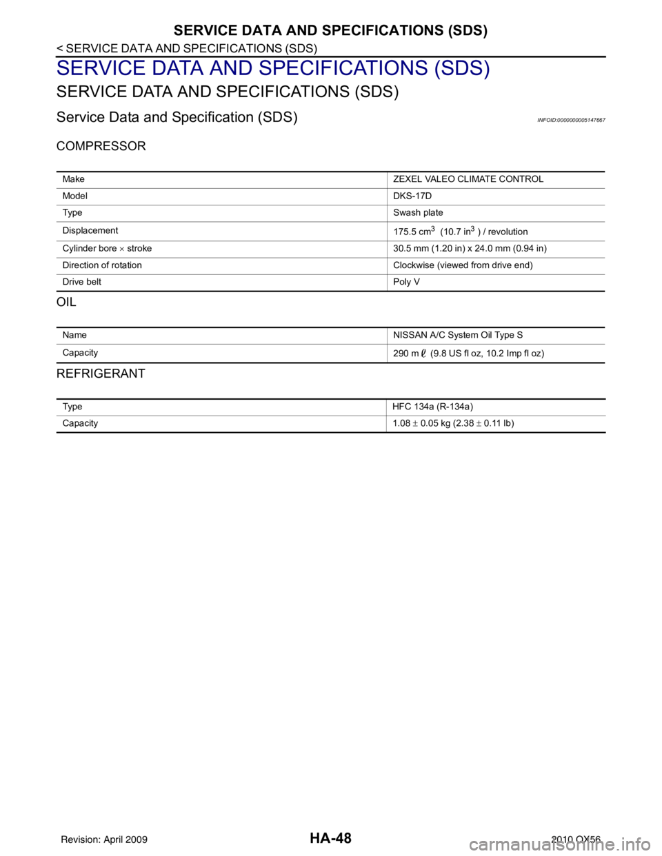
COMPRESSOR
OIL
REFRIGERANT
Make ZEXEL VALEO CLIMATE CONTROL
Model DKS-17D
Ty p e Swash plate
Displacement 175.5 cm
3 (10.7 in3 ) / revolution
Cylinder bore × stroke 30.5 mm (1.20 in) x 24.0 mm (0.94 in)
Direction of rotation Clockwise (viewed from drive end)
Drive belt Poly V
Name NISSAN A/C System Oil Type S
Capacity 290 m (9.8 US fl oz, 10.2 Imp fl oz)
Ty p eHFC 134a (R-134a)
Capacity 1.08 ± 0.05 kg (2.38 ± 0.11 lb)
Revision: April 20092010 QX56
Page 2695 of 4210
ENGINE OILLU-9
< ON-VEHICLE MAINTENANCE >
C
DE
F
G H
I
J
K L
M A
LU
NP
O
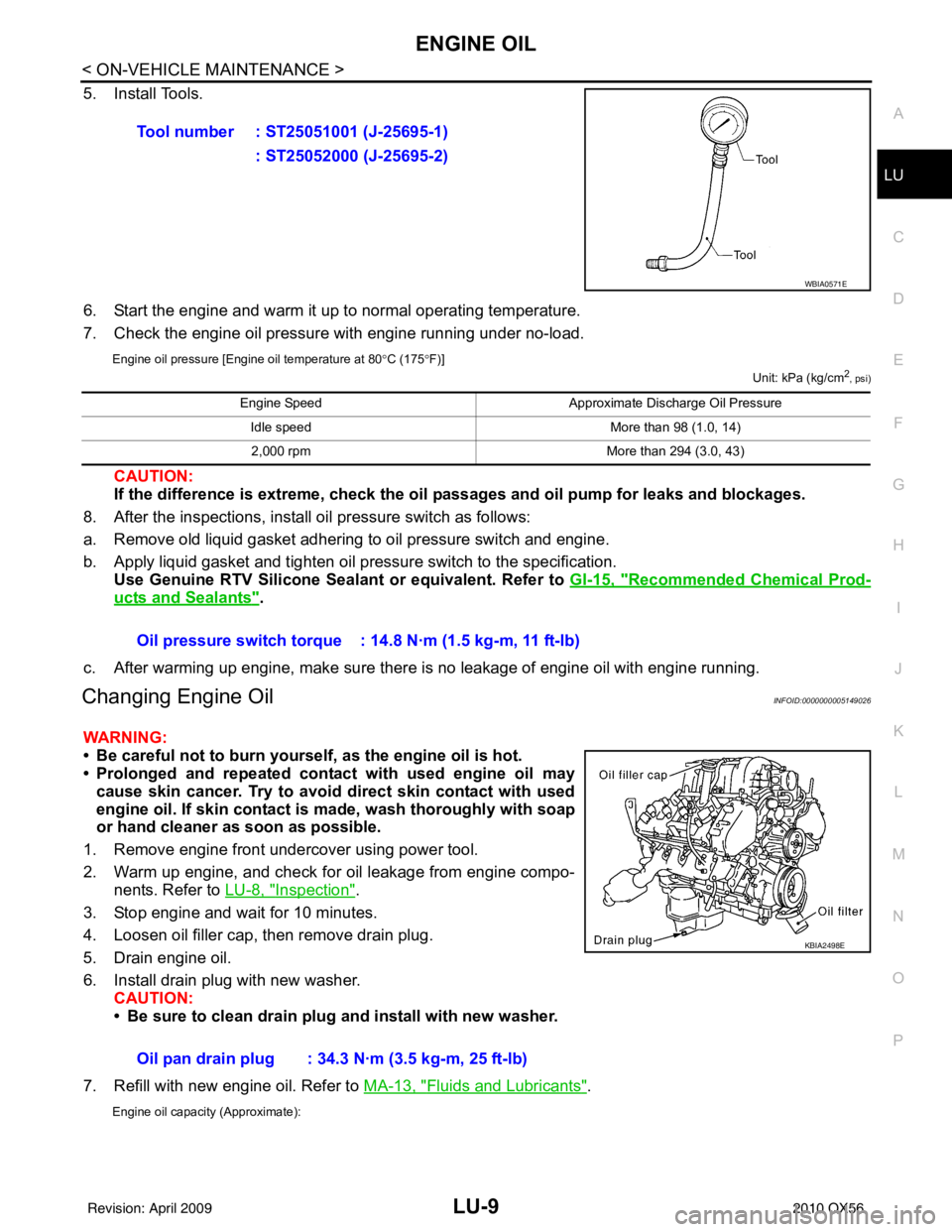
5. Install Tools.
6. Start the engine and warm it up to normal operating temperature.
7. Check the engine oil pressure with engine running under no-load.
Engine oil pressure [Engine oil temperature at 80
°C (175 °F)]
Unit: kPa (kg/cm2, psi)
CAUTION:
If the difference is extreme, check the oil passages and oil pump for leaks and blockages.
8. After the inspections, install oil pressure switch as follows:
a. Remove old liquid gasket adhering to oil pressure switch and engine.
b. Apply liquid gasket and tighten oil pressure switch to the specification. Use Genuine RTV Silicone Seal ant or equivalent. Refer to GI-15, "
Recommended Chemical Prod-
ucts and Sealants".
c. After warming up engine, make sure there is no leakage of engine oil with engine running.
Changing Engine OilINFOID:0000000005149026
WARNING:
• Be careful not to burn yourself, as the engine oil is hot.
• Prolonged and repeated contact with used engine oil may cause skin cancer. Try to avoid direct skin contact with used
engine oil. If skin contact is made, wash thoroughly with soap
or hand cleaner as soon as possible.
1. Remove engine front undercover using power tool.
2. Warm up engine, and check for oil leakage from engine compo- nents. Refer to LU-8, "
Inspection".
3. Stop engine and wait for 10 minutes.
4. Loosen oil filler cap, then remove drain plug.
5. Drain engine oil.
6. Install drain plug with new washer. CAUTION:
• Be sure to clean drain plug and install with new washer.
7. Refill with new engine oil. Refer to MA-13, "
Fluids and Lubricants".
Engine oil capacity (Approximate):
Tool number : ST25051001 (J-25695-1)
: ST25052000 (J-25695-2)
WBIA0571E
Engine Speed Approximate Discharge Oil Pressure
Idle speed More than 98 (1.0, 14)
2,000 rpm More than 294 (3.0, 43)
Oil pressure switch torque : 14.8 N·m (1.5 kg-m, 11 ft-lb)
Oil pan drain plug : 34.3 N·m (3.5 kg-m, 25 ft-lb)
KBIA2498E
Revision: April 20092010 QX56
Page 2696 of 4210
LU-10
< ON-VEHICLE MAINTENANCE >
ENGINE OIL
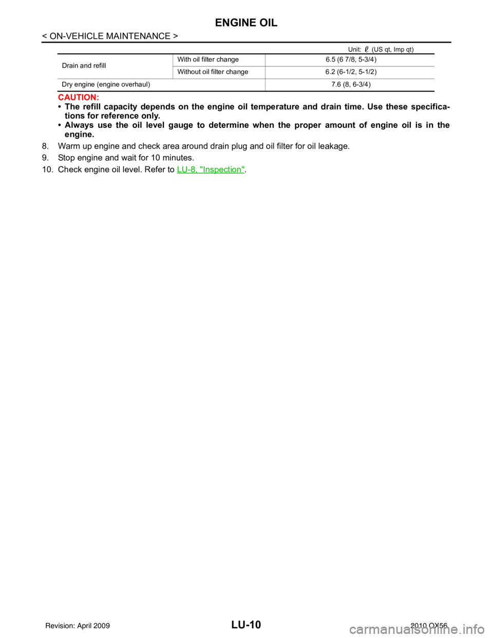
Unit: (US qt, Imp qt)
CAUTION:
• The refill capacity depends on the engine oil temperature and drain time. Use these specifica-
tions for reference only.
• Always use the oil level gauge to determine when the proper amount of engine oil is in the engine.
8. Warm up engine and check area around drain plug and oil filter for oil leakage.
9. Stop engine and wait for 10 minutes.
10. Check engine oil level. Refer to LU-8, "
Inspection".
Drain and refill With oil filter change
6.5 (6 7/8, 5-3/4)
Without oil filter change 6.2 (6-1/2, 5-1/2)
Dry engine (engine overhaul) 7.6 (8, 6-3/4)
Revision: April 20092010 QX56
Page 2704 of 4210
LU-18
< SERVICE DATA AND SPECIFICATIONS (SDS)
SERVICE DATA AND SPECIFICATIONS (SDS)
SERVICE DATA AND SPECIFICATIONS (SDS)
SERVICE DATA AND SPECIFICATIONS (SDS)
Standard and LimitINFOID:0000000005149033
OIL PRESSURE
Unit: kPa (kg/cm2, psi)
OIL PUMP
Unit: mm (in)
REGULATOR VALVE
Unit: mm (in)
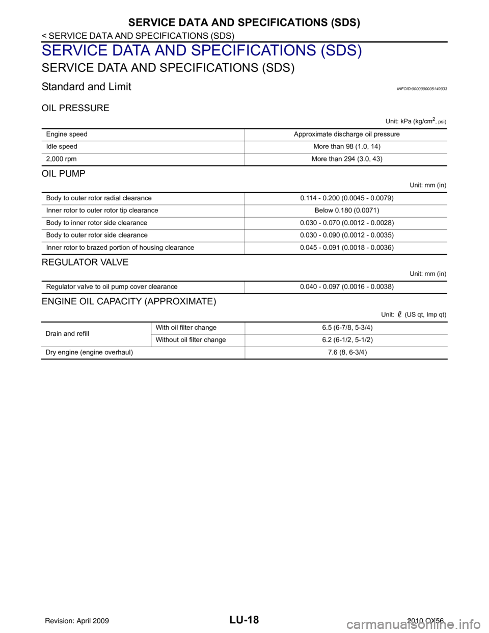
ENGINE OIL CAPACITY (APPROXIMATE)
Unit: (US qt, Imp qt)
Engine speed Approximate discharge oil pressure
Idle speed More than 98 (1.0, 14)
2,000 rpm More than 294 (3.0, 43)
Body to outer rotor radial clearance0.114 - 0.200 (0.0045 - 0.0079)
Inner rotor to outer rotor tip clearance Below 0.180 (0.0071)
Body to inner rotor side clearance 0.030 - 0.070 (0.0012 - 0.0028)
Body to outer rotor side clearance 0.030 - 0.090 (0.0012 - 0.0035)
Inner rotor to brazed portion of housing clearance 0.045 - 0.091 (0.0018 - 0.0036)
Regulator valve to oil pump cover clearance 0.040 - 0.097 (0.0016 - 0.0038)
Drain and refillWith oil filter change 6.5 (6-7/8, 5-3/4)
Without oil filter change
6.2 (6-1/2, 5-1/2)
Dry engine (engine overhaul) 7.6 (8, 6-3/4)
Revision: April 20092010 QX56
Page 2717 of 4210
RECOMMENDED FLUIDS AND LUBRICANTSMA-13
< ON-VEHICLE MAINTENANCE >
C
DE
F
G H
I
J
K L
M B
MA
N
O A
RECOMMENDED FLUIDS AND LUBRICANTS
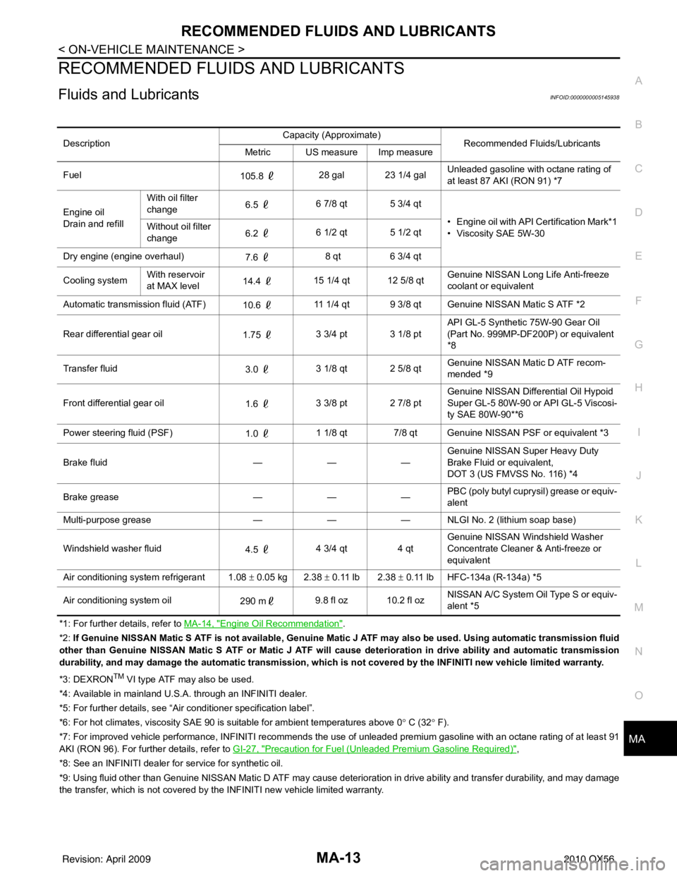
Fluids and LubricantsINFOID:0000000005145938
*1: For further details, refer to
MA-14, "Engine Oil Recommendation".
*2: If Genuine NISSAN Matic S ATF is not ava ilable, Genuine Matic J ATF may also be used. Using automatic transmission fluid
other than Genuine NISSAN Matic S ATF or Matic J ATF will cause deterioration in drive ability and automatic transmission
durability, and may damage the automatic transmission, which is not covered by the INFINITI new vehicle limited warranty.
*3: DEXRON
TM VI type ATF may also be used.
*4: Available in mainland U.S.A. through an INFINITI dealer.
*5: For further details, see “Air conditioner specification label”.
*6: For hot climates, viscosity SAE 90 is suitable for ambient temperatures above 0° C (32° F).
*7: For improved vehicle performance, INFINITI recommends the use of unleaded premium gasoline with an octane rating of at leas t 91
AKI (RON 96). For furt her details, refer to GI-27, "
Precaution for Fuel (Unleaded Premium Gasoline Required)",
*8: See an INFINITI dealer for service for synthetic oil.
*9: Using fluid other than Genuin e NISSAN Matic D ATF may cause deterioration in drive ability and transfer durability, and may damage
the transfer, which is not covered by the INFINITI new vehicle limited warranty. Description
Capacity (Approximate)
Recommended Fluids/Lubricants
Metric US measure Imp measure
Fuel 105.8 28 gal 23 1/4 gal Unleaded gasoline with octane rating of
at least 87 AKI (RON 91) *7
Engine oil
Drain and refill With oil filter
change
6.5
6 7/8 qt 5 3/4 qt
• Engine oil with API Certification Mark*1
• Viscosity SAE 5W-30
Without oil filter
change
6.2
6 1/2 qt 5 1/2 qt
Dry engine (engine overhaul) 7.6 8 qt
6 3/4 qt
Cooling system With reservoir
at MAX level
14.4
15 1/4 qt 12 5/8 qt Genuine NISSAN Long
Life Anti-freeze
coolant or equivalent
Automatic transmission fluid (ATF) 10.6 11 1/4 qt 9 3/8 qt Genuine NISSAN Matic S ATF *2
Rear differential gear oil 1.75 3 3/4 pt 3 1/8 pt API GL-5 Synthetic 75W-90 Gear Oil
(Part No. 999MP-DF200P) or equivalent
*8
Transfer fluid 3.0 3 1/8 qt 2 5/8 qt Genuine NISSAN Matic D ATF recom-
mended *9
Front differential gear oil 1.6 3 3/8 pt 2 7/8 pt Genuine NISSAN Differ
ential Oil Hypoid
Super GL-5 80W-90 or API GL-5 Viscosi-
ty SAE 80W-90**6
Power steering fluid (PSF) 1.0 1 1/8 qt 7/8 qt Genuine NISSAN PSF or equivalent *3
Brake fluid ———Genuine NISSAN S
uper Heavy Duty
Brake Fluid or equivalent,
DOT 3 (US FMVSS No. 116) *4
Brake grease ———PBC (poly butyl cuprysil) grease or equiv-
alent
Multi-purpose grease ——— NLGI No. 2 (lithium soap base)
Windshield washer fluid 4.5 4 3/4 qt
4 qtGenuine NISSAN Wind
shield Washer
Concentrate Cleaner & Anti-freeze or
equivalent
Air conditioning system refrigerant 1.08 ± 0.05 kg 2.38 ± 0.11 lb 2.38 ± 0.11 lb HFC-134a (R-134a) *5
Air conditioning system oil 290 m9.8 fl oz 10.2 fl oz NISSAN A/C System Oil Type S or equiv-
alent *5
Revision: April 20092010 QX56
Page 2722 of 4210
MA-18
< ON-VEHICLE MAINTENANCE >
ENGINE MAINTENANCE
5. Remove the reservoir tank to drain the engine coolant, then clean the reservoir tank before installing it.
6. Check the drained coolant for contaminants such as rust, corrosion or discoloration.
If the coolant is contaminated, flush the engine cooling system. Refer to MA-17, "
ENGINE COOLANT :
Changing Engine Coolant".
REFILLING ENGINE COOLANT
1. Close the radiator drain plug. Install the reservoir tank, cylinder block drain plug, and the oil cooler hose, if
removed for a total system drain or for engine removal or repair.
• The radiator must be completely empty of coolant and water.
• Apply sealant to the threads of the cylinder bl ock drain plug. Use Genuine High Performance Thread
Sealant or equivalent. Refer to GI-15, "
Recommended Chemical Products and Sealants".
2. Set the vehicle heater controls to the full HOT and heat er ON position. Turn the vehicle ignition ON with
the engine OFF as necessary to activate the heater mode.
3. Remove the vented reservoir cap and replace it with a non-vented reservoir cap before filling the cooling
system.
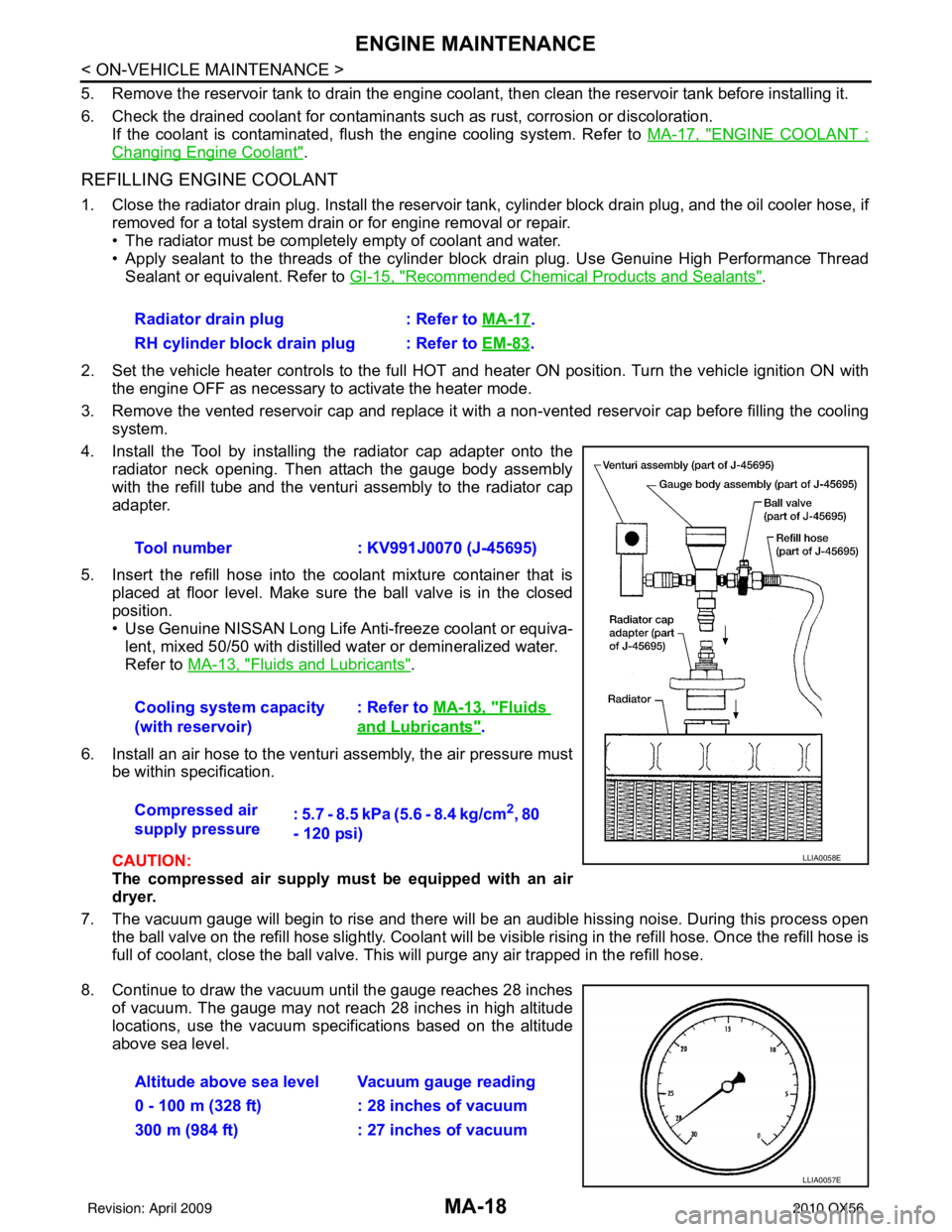
4. Install the Tool by installing the radiator cap adapter onto the radiator neck opening. Then attach the gauge body assembly
with the refill tube and the venturi assembly to the radiator cap
adapter.
5. Insert the refill hose into the coolant mixture container that is placed at floor level. Make sure the ball valve is in the closed
position.
• Use Genuine NISSAN Long Life Anti-freeze coolant or equiva-lent, mixed 50/50 with distilled water or demineralized water.
Refer to MA-13, "
Fluids and Lubricants".
6. Install an air hose to the venturi assembly, the air pressure must be within specification.
CAUTION:
The compressed air supply must be equipped with an air
dryer.
7. The vacuum gauge will begin to rise and there will be an audible hissing noise. During this process open the ball valve on the refill hose slightly. Coolant will be vi sible rising in the refill hose. Once the refill hose is
full of coolant, close the ball valve. This will purge any air trapped in the refill hose.
8. Continue to draw the vacuum until the gauge reaches 28 inches of vacuum. The gauge may not reach 28 inches in high altitude
locations, use the vacuum specifications based on the altitude
above sea level.Radiator drain plug
: Refer to MA-17
.
RH cylinder block drain plug : Refer to EM-83
.
Tool number : KV991J0070 (J-45695)
Cooling system capacity
(with reservoir) : Refer to
MA-13, "
Fluids
and Lubricants".
Compressed air
supply pressure : 5.7 - 8.5 kPa (5.6 - 8.4 kg/cm
2, 80
- 120 psi)
LLIA0058E
Altitude above sea level Vacuum gauge reading
0 - 100 m (328 ft) : 28 inches of vacuum
300 m (984 ft) : 27 inches of vacuum
LLIA0057E
Revision: April 20092010 QX56