2010 INFINITI QX56 manual transmission
[x] Cancel search: manual transmissionPage 2249 of 4210
GI-26
< PRECAUTION >
PRECAUTIONS
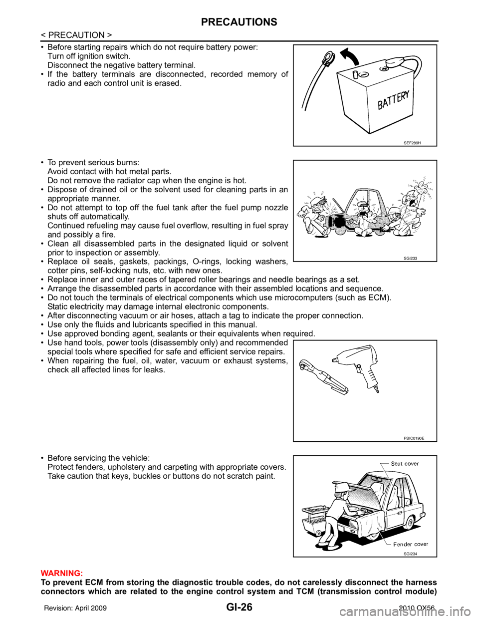
• Before starting repairs which do not require battery power:Turn off ignition switch.
Disconnect the negative battery terminal.
• If the battery terminals are disconnected, recorded memory of radio and each control unit is erased.
• To prevent serious burns: Avoid contact with hot metal parts.
Do not remove the radiator cap when the engine is hot.
• Dispose of drained oil or the solvent used for cleaning parts in an appropriate manner.
• Do not attempt to top off the fuel tank after the fuel pump nozzle
shuts off automatically.
Continued refueling may cause fuel overflow, resulting in fuel spray
and possibly a fire.
• Clean all disassembled parts in the designated liquid or solvent prior to inspection or assembly.
• Replace oil seals, gaskets, packings, O-rings, locking washers,
cotter pins, self-locking nuts, etc. with new ones.
• Replace inner and outer races of tapered roller bearings and needle bearings as a set.
• Arrange the disassembled parts in accordance with their assembled locations and sequence.
• Do not touch the terminals of electrical com ponents which use microcomputers (such as ECM).
Static electricity may damage internal electronic components.
• After disconnecting vacuum or air hoses, atta ch a tag to indicate the proper connection.
• Use only the fluids and lubricants specified in this manual.
• Use approved bonding agent, sealants or their equivalents when required.
• Use hand tools, power tools (disassembly only) and recommended special tools where specified for safe and efficient service repairs.
• When repairing the fuel, oil, water, vacuum or exhaust systems, check all affected lines for leaks.
• Before servicing the vehicle: Protect fenders, upholstery and carpeting with appropriate covers.
Take caution that keys, buckles or buttons do not scratch paint.
WARNING:
To prevent ECM from storing the diagnostic tro uble codes, do not carelessly disconnect the harness
connectors which are related to the engine control system and TCM (transmission control module)
SEF289H
SGI233
PBIC0190E
SGI234
Revision: April 20092010 QX56
Page 2255 of 4210
GI-32
< PRECAUTION >
TOW TRUCK TOWING
TOW TRUCK TOWING
Tow Truck TowingINFOID:0000000005370267
WARNING:
• Never get under the vehicle while it is supported only by the jack. Always use safety stands to sup-
port the frame when you have to get under the vehicle.
• Place wheel chocks at both front an d back of the wheels on the ground.
CAUTION:
• All applicable State or Provincial (in Canada) laws and local laws regarding the towing operation
must be obeyed.
• It is necessary to use proper towing equipment to avoid possible damage during towing operation.
Towing is in accordance with Towing Procedure Manual at dealer.
• Always attach safety chains before towing.
• When towing, make sure that the transmission, steering system and powertrain are in good order. If any unit is damaged, dollies must be used.
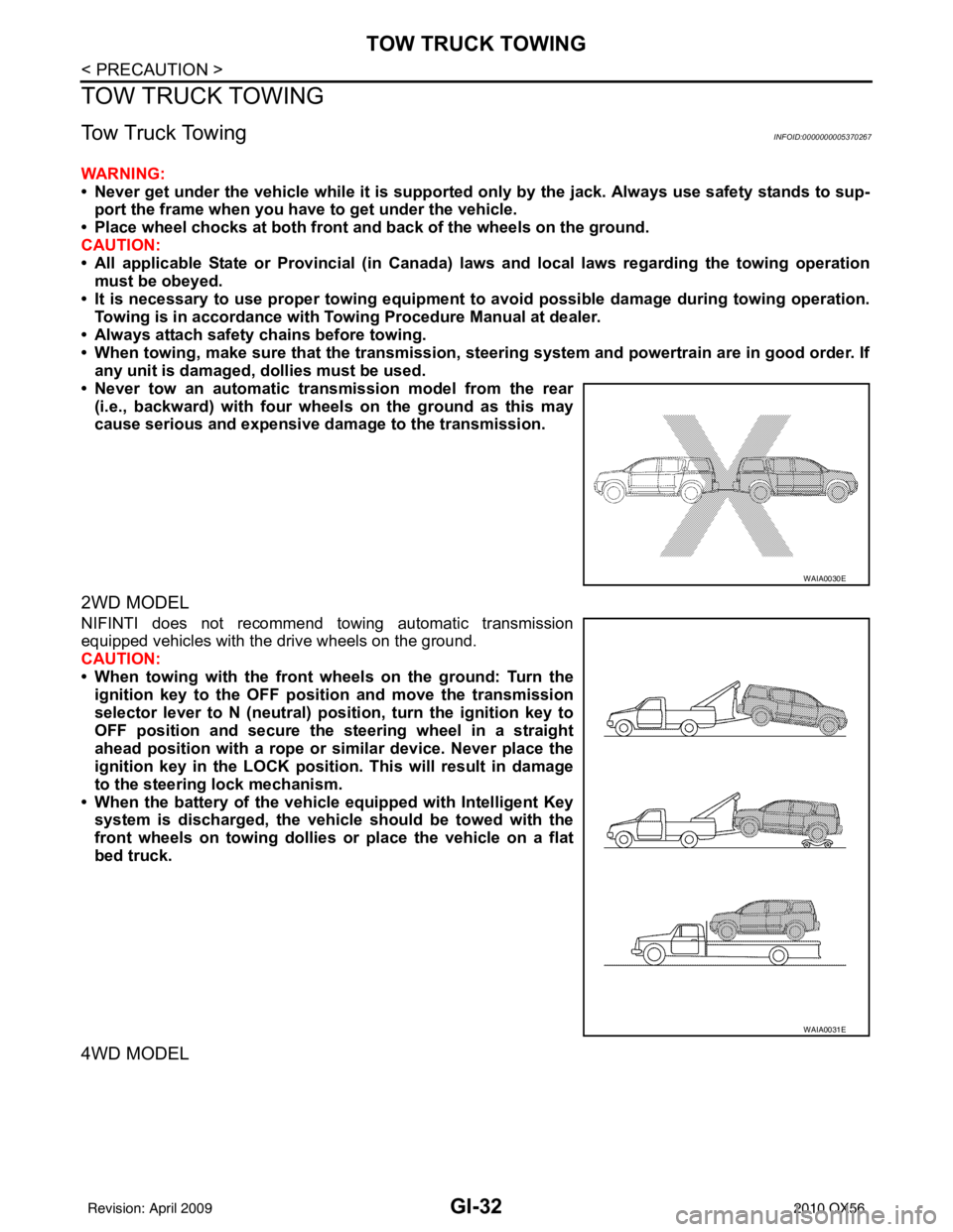
• Never tow an automatic transmission model from the rear (i.e., backward) with four wh eels on the ground as this may
cause serious and expensive dama ge to the transmission.
2WD MODEL
NIFINTI does not recommend towing automatic transmission
equipped vehicles with the drive wheels on the ground.
CAUTION:
• When towing with the front wheels on the ground: Turn the
ignition key to the OFF posit ion and move the transmission
selector lever to N (neutral) pos ition, turn the ignition key to
OFF position and secure the steering wheel in a straight
ahead position with a rope or similar device. Never place the
ignition key in the LOCK position. This will result in damage
to the steering lock mechanism.
• When the battery of the vehicle equipped with Intelligent Key system is discharged, the vehicle should be towed with the
front wheels on towing dollies or place the vehicle on a flat
bed truck.
4WD MODEL
WAIA0030E
WAIA0031E
Revision: April 20092010 QX56
Page 2257 of 4210
GI-34
< BASIC INSPECTION >
SERVICE INFORMATION FOR ELECTRICAL INCIDENT
BASIC INSPECTION
SERVICE INFORMATION FOR ELECTRICAL INCIDENT
Work FlowINFOID:0000000005149604
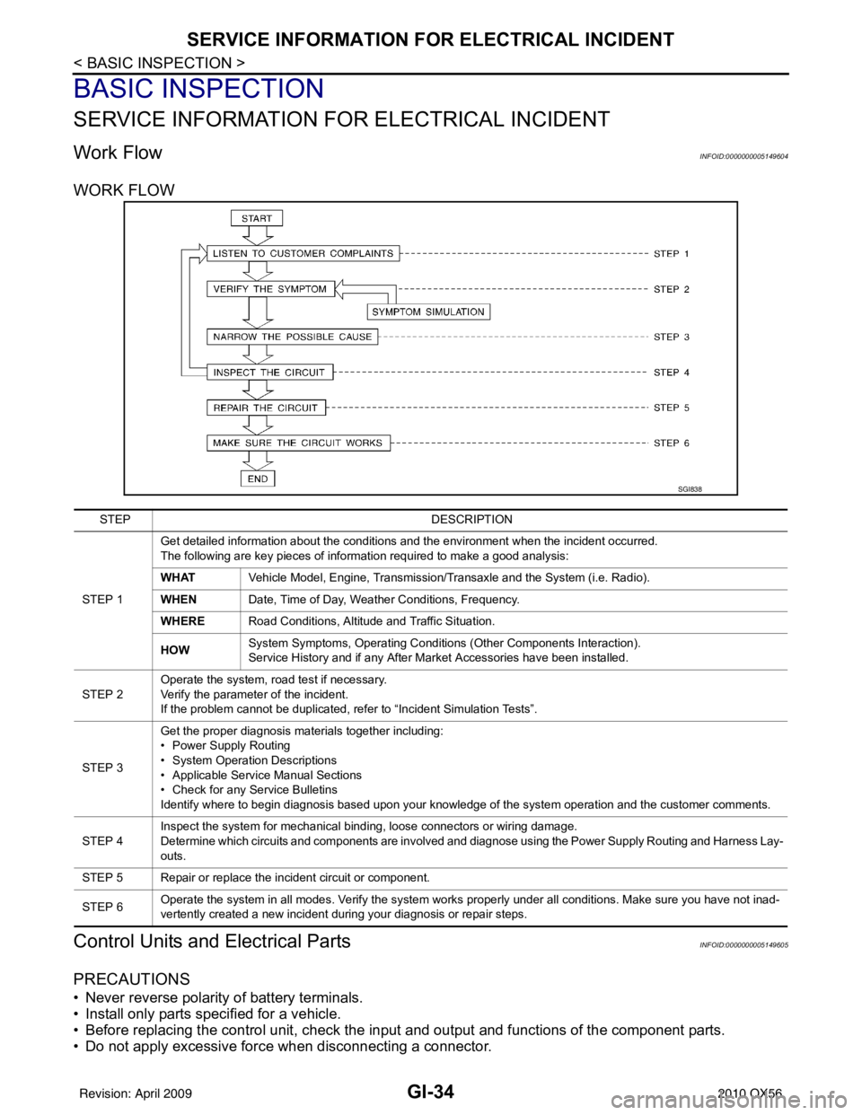
WORK FLOW
Control Units and Electrical PartsINFOID:0000000005149605
PRECAUTIONS
• Never reverse polarity of battery terminals.
• Install only parts specified for a vehicle.
• Before replacing the control unit, check the i nput and output and functions of the component parts.
• Do not apply excessive force when disconnecting a connector.
SGI838
STEP DESCRIPTION
STEP 1 Get detailed information about the conditions and the environment when the incident occurred.
The following are key pieces of information required to make a good analysis:
WHAT
Vehicle Model, Engine, Transmission/Transaxle and the System (i.e. Radio).
WHEN Date, Time of Day, Weather Conditions, Frequency.
WHERE Road Conditions, Altitude and Traffic Situation.
HOW System Symptoms, Operating Conditions
(Other Components Interaction).
Service History and if any After Market Accessories have been installed.
STEP 2 Operate the system, road test if necessary.
Verify the parameter of the incident.
If the problem cannot be duplicated, refer to “Incident Simulation Tests”.
STEP 3 Get the proper diagnosis materials together including:
• Power Supply Routing
• System Operation Descriptions
• Applicable Service Manual Sections
• Check for any Service Bulletins
Identify where to begin diagnosis based upon your knowledge of the system operation and the customer comments.
STEP 4 Inspect the system for mechanical binding, loose connectors or wiring damage.
Determine which circuits and components are involved and diagnose using the Power Supply Routing and Harness Lay-
outs.
STEP 5 Repair or replace the incident circuit or component.
STEP 6 Operate the system in all modes. Verify the system works properly under all conditions. Make sure you have not inad-
vertently created a new incident during your diagnosis or repair steps.
Revision: April 20092010 QX56
Page 2269 of 4210
GI-46
< BASIC INSPECTION >
CONSULT-III CHECKING SYSTEM
CONSULT-III CHECKING SYSTEM
DescriptionINFOID:0000000005149609
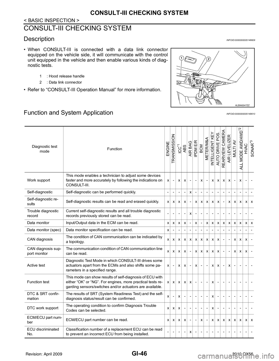
• When CONSULT-III is connected with a data link connectorequipped on the vehicle side, it will communicate with the control
unit equipped in the vehicle and then enable various kinds of diag-
nostic tests.
• Refer to “CONSULT-III Operation Manual” for more information.
Function and System ApplicationINFOID:0000000005149610
1 : Hood release handle
2 : Data link connector
ALBIA0047ZZ
Diagnostic test mode Function
ENGINE
TRANSMISSION
ICC
*1
ABS
AIR BAG
IPDM E/R
BCM
METER/M&A
INTELLIGENT KEY
AUTO DRIVE POS.
REARVIEW CAMERA
AIR LEVELIZER MULTI AV
ALL MODE AWD/4WD
*2
HVAC
SONAR
*3
Work support This mode enables a technician to adjust some devices
faster and more accurately by following the indications on
CONSULT-III. x- x x- - x- xxxx- x - -
Self-diagnostic Self-diagnostic can be performed quickly. ----x-----------
Self-diagnostic re-
sults Self-diagnostic results can be read and erased quickly. x x x x - x x x x x - x x x x x
Trouble diagnostic
record Current self-diagnostic results and all trouble diagnostic
records previously stored can be read.
--- - x--- - -------
Data monitor Input/Output data in the ECM can be read. xxx x- x- xxxxxxx xx
Data monitor (spec) Data monitor specification can be read. x---------------
CAN diagnosis The condition of CAN communication can be indicated by
a topology.
xxx xxxxxxx- - xx x-
CAN diagnosis sup-
port monitor The communication condition of CAN communication line
can be read.
xxx x- xxxxx- - xx x-
Active test Diagnostic Test Mode in wh
ich CONSULT-III drives some
actuators apart from the ECMs and also shifts some pa-
rameters in a specified range. x-xx-x--xx-x- - --
Function test This mode can show results of self-diagnosis of ECU with
either “OK” or “NG”. For engines, more practical tests re-
garding sensors/switches and/or actuators are available.
xxxxx---x-------
DTC & SRT confir-
mation The results of SRT (System Readiness Test) and the self-
diagnosis status/result can be confirmed.
x-x-----x-------
DTC work support The operating condition to confirm Diagnosis Trouble
Codes can be selected. xxx-----x-------
ECM/ECU part num-
ber ECM/ECU part number can be read.
xxx x- - x- xxxxxx xx
ECU discriminated
No. Classification number of a replacement ECU can be read
to prevent an incorrect ECU from being installed.
----x-----------
Revision: April 20092010 QX56
Page 2634 of 4210
![INFINITI QX56 2010 Factory Service Manual LAN-36
< HOW TO USE THIS MANUAL >[CAN]
HOW TO USE THIS SECTION
HOW TO USE THIS MANUAL
HOW TO USE THIS SECTION
CautionINFOID:0000000005146452
• This section describes information peculiar to a v
ehic INFINITI QX56 2010 Factory Service Manual LAN-36
< HOW TO USE THIS MANUAL >[CAN]
HOW TO USE THIS SECTION
HOW TO USE THIS MANUAL
HOW TO USE THIS SECTION
CautionINFOID:0000000005146452
• This section describes information peculiar to a v
ehic](/manual-img/42/57032/w960_57032-2633.png)
LAN-36
< HOW TO USE THIS MANUAL >[CAN]
HOW TO USE THIS SECTION
HOW TO USE THIS MANUAL
HOW TO USE THIS SECTION
CautionINFOID:0000000005146452
• This section describes information peculiar to a v
ehicle, sheets for trouble diagnosis, and inspection proce-
dures.
• For trouble diagnosis procedure, refer to LAN-14, "
Trouble Diagnosis Procedure".
Abbreviation ListINFOID:0000000005146453
Abbreviations in CAN communication signal chart, and the diagnosis sheet are as per the following list.
AbbreviationUnit nameSELECT SYSTEM
(CONSULT-III) CAN DIAG SUPPORT MNTR
(CONSULT-III)
4WD Transfer control unit ALL MODE AWD/4WDAWD/4WD
A-BAG Air bag diagnosis sensor unit AIR BAG—
ABS ABS actuator and electric unit (control unit) ABSVDC/TCS/ABS
ADP Driver seat control unit AUTO DRIVE POS.—
AV AV c o n t r o l u n i t M U LT I AVD I S P L AY
BCM BCM BCMBCM/SEC
DLC Data link connector ——
ECM ECM ENGINEECM
HVAC A/C auto amp. HVAC—
ICC ICC unit ICCICC
ICC/e4WD
I-KEY Intelligent Key unit INTELLIGENT KEYI-KEY
IPDM-E IPDM E/R IPDM E/RIPDM E/R
LASER ICC sensor —ICC SENSOR
M&A Combination meter METER/M&AMETER/M&A
STRG Steering angle sensor —STRG
TCM TCMTRANSMISSION TCM
Revision: April 20092010 QX56
Page 3378 of 4210
![INFINITI QX56 2010 Factory Service Manual U1010 CONTROL UNIT (CAN)SEC-27
< COMPONENT DIAGNOSIS > [WITH INTELLIGENT KEY SYSTEM]
C
D
E
F
G H
I
J
L
M A
B
SEC
N
O P
U1010 CONTROL UNIT (CAN)
DescriptionINFOID:0000000005147086
CAN (Controller Area INFINITI QX56 2010 Factory Service Manual U1010 CONTROL UNIT (CAN)SEC-27
< COMPONENT DIAGNOSIS > [WITH INTELLIGENT KEY SYSTEM]
C
D
E
F
G H
I
J
L
M A
B
SEC
N
O P
U1010 CONTROL UNIT (CAN)
DescriptionINFOID:0000000005147086
CAN (Controller Area](/manual-img/42/57032/w960_57032-3377.png)
U1010 CONTROL UNIT (CAN)SEC-27
< COMPONENT DIAGNOSIS > [WITH INTELLIGENT KEY SYSTEM]
C
D
E
F
G H
I
J
L
M A
B
SEC
N
O P
U1010 CONTROL UNIT (CAN)
DescriptionINFOID:0000000005147086
CAN (Controller Area Network) is a serial communication line for real time applications. It is an on-vehicle mul-
tiplex communication line with high data communicati on speed and excellent error detection ability. Modern
vehicle is equipped with many electronic control unit, and each control unit shares information and links with
other control units during operation (not independent). In CAN communication, control units are connected
with 2 communication lines (CAN-H line, CAN-L line) allowing a high rate of information transmission with less
wiring. Each control unit transmits/receives data but selectively reads required data only.
CAN Communication Signal Chart, refer to LAN-44, "
CAN Communication Signal Chart".
DTC LogicINFOID:0000000005147087
DTC DETECTION LOGIC
Diagnosis ProcedureINFOID:0000000005147088
1.REPLACE INTELLIGENT KEY UNIT
When DTC [U1010] is detected, replace Intelligent Key unit.
>> Replace Intelligent Key unit.
Special Repair RequirementINFOID:0000000005147089
1.REQUIRED WORK WHEN REPLACING INTELLIGENT KEY UNIT
Initialize control unit. Refer to CONSULT-III Operation Manual.
>> Inspection End.
DTC CONSULT-III display de-
scription DTC Detection Condit
ion Possible cause
U1010 CONTROL UNIT (CAN) When detecting error during the initial diagnosis of CAN control-
ler of Intelligent Key unit. Intelligent Key unit
Revision: April 20092010 QX56
Page 3838 of 4210
PRECAUTIONSTM-143
< PRECAUTION >
CEF
G H
I
J
K L
M A
B
TM
N
O P
PRECAUTION
PRECAUTIONS
Precaution for Supplemental Restraint System (SRS) "AIR BAG" and "SEAT BELT
PRE-TENSIONER"
INFOID:0000000005148716
The Supplemental Restraint System such as “AIR BAG” and “SEAT BELT PRE-TENSIONER”, used along
with a front seat belt, helps to reduce the risk or severi ty of injury to the driver and front passenger for certain
types of collision. This system includes seat belt switch inputs and dual stage front air bag modules. The SRS
system uses the seat belt switches to determine the front air bag deployment, and may only deploy one front
air bag, depending on the severity of a collision and w hether the front occupants are belted or unbelted.
Information necessary to service the system safely is included in the SR and SB section of this Service Man-
ual.
WARNING:
• To avoid rendering the SRS inoper ative, which could increase the risk of personal injury or death in
the event of a collision which would result in air bag inflation, all maintenance must be performed by
an authorized NISSAN/INFINITI dealer.
• Improper maintenance, including in correct removal and installation of the SRS, can lead to personal
injury caused by unintentional act ivation of the system. For removal of Spiral Cable and Air Bag
Module, see the SR section.
• Do not use electrical test equipm ent on any circuit related to the SRS unless instructed to in this
Service Manual. SRS wiring harnesses can be identi fied by yellow and/or orange harnesses or har-
ness connectors.
Precaution for On Board Diagnosis (OBD) System of A/T and EngineINFOID:0000000005148717
The ECM has an on board diagnostic system . It will light up the malfunction indicator lamp (MIL) to warn the
driver of a malfunction causing emission deterioration.
CAUTION:
• Be sure to turn the ignition switch “OFF” and disconnect the negative battery cable before any repair or inspection work. The open/short circuit of related switches, sen sors, solenoid valves, etc. Will
cause the MIL to light up.
• Be sure to connect and lock the connectors secure ly after work. A loose (unlocked) connector will
cause the MIL to light up due to an open circuit. (Be sure the connector is free from water, grease,
dirt, bent terminals, etc.)
• Be sure to route and secure the harnesses properly after work. Interference of the harness with a
bracket, etc. May cause the MIL to li ght up due to a short circuit.
• Be sure to connect rubber tubes properly afte r work. A misconnected or disconnected rubber tube
may cause the MIL to light up due to a malfunction of the EGR system or fuel injection system, etc.
• Be sure to erase the unnecessary malfunction informa tion (repairs completed) from the TCM and
ECM before returning the vehicle to the customer.
PrecautionINFOID:0000000005148718
NOTE:
If any malfunctions occur in th e RE5R05A model transmission, repl ace the entire transmission assem-
bly.
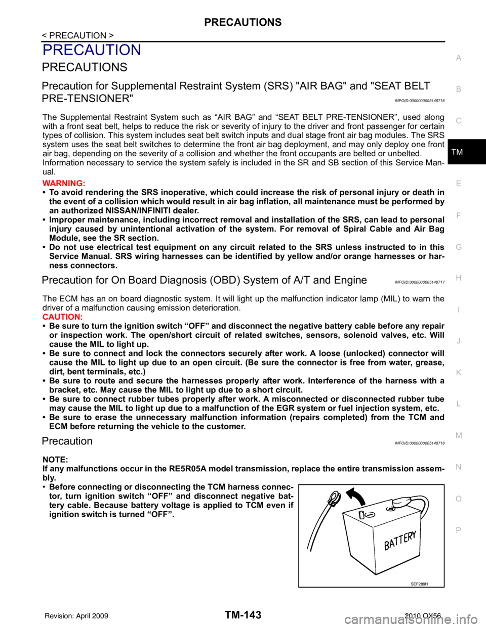
• Before connecting or disconn ecting the TCM harness connec-
tor, turn ignition switch “O FF” and disconnect negative bat-
tery cable. Because battery voltage is applied to TCM even if
ignition switch is turned “OFF”.
SEF289H
Revision: April 20092010 QX56
Page 3869 of 4210
TM-174
< ON-VEHICLE REPAIR >
CONTROL VALVE WITH TCM
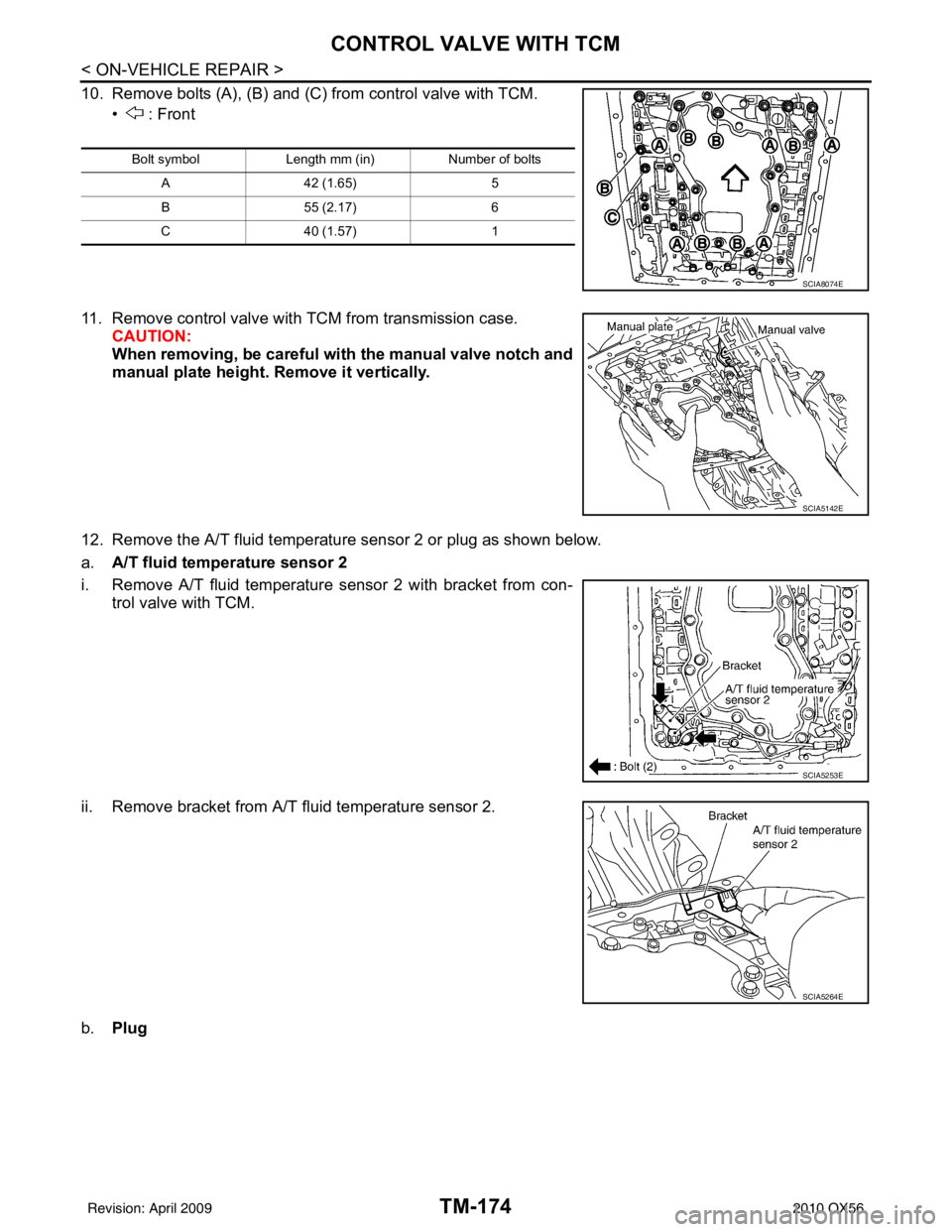
10. Remove bolts (A), (B) and (C) from control valve with TCM.• : Front
11. Remove control valve with TCM from transmission case. CAUTION:
When removing, be careful with the manual valve notch and
manual plate height. Remove it vertically.
12. Remove the A/T fluid temperature sensor 2 or plug as shown below.
a. A/T fluid temperature sensor 2
i. Remove A/T fluid temperature sensor 2 with bracket from con- trol valve with TCM.
ii. Remove bracket from A/T fluid temperature sensor 2.
b. Plug
Bolt symbol Length mm (in) Number of bolts
A 42 (1.65) 5
B 55 (2.17) 6
C 40 (1.57) 1
SCIA8074E
SCIA5142E
SCIA5253E
SCIA5264E
Revision: April 20092010 QX56