2010 INFINITI QX56 dimensions
[x] Cancel search: dimensionsPage 1953 of 4210
EM-102
< DISASSEMBLY AND ASSEMBLY >
HOW TO SELECT PISTON AND BEARING
When Cylinder Block is Reused
1. Measure cylinder block bore diameter.
2. Determine the bore grade by comparing the measurement with the values under the “Cylinder bore diam-
eter” of the piston selection table.
Piston Selection Table
Unit: mm (in)
NOTE:
• The piston is available together with piston pin as an assembly.
• The piston pin (piston pin bore) grade is provided only for the parts installed at the plant. For service parts, no grades can be selected (only 0 grade is available).
HOW TO SELECT CONNECTING ROD BEARING
When New Connecting Rod and Crankshaft are Used
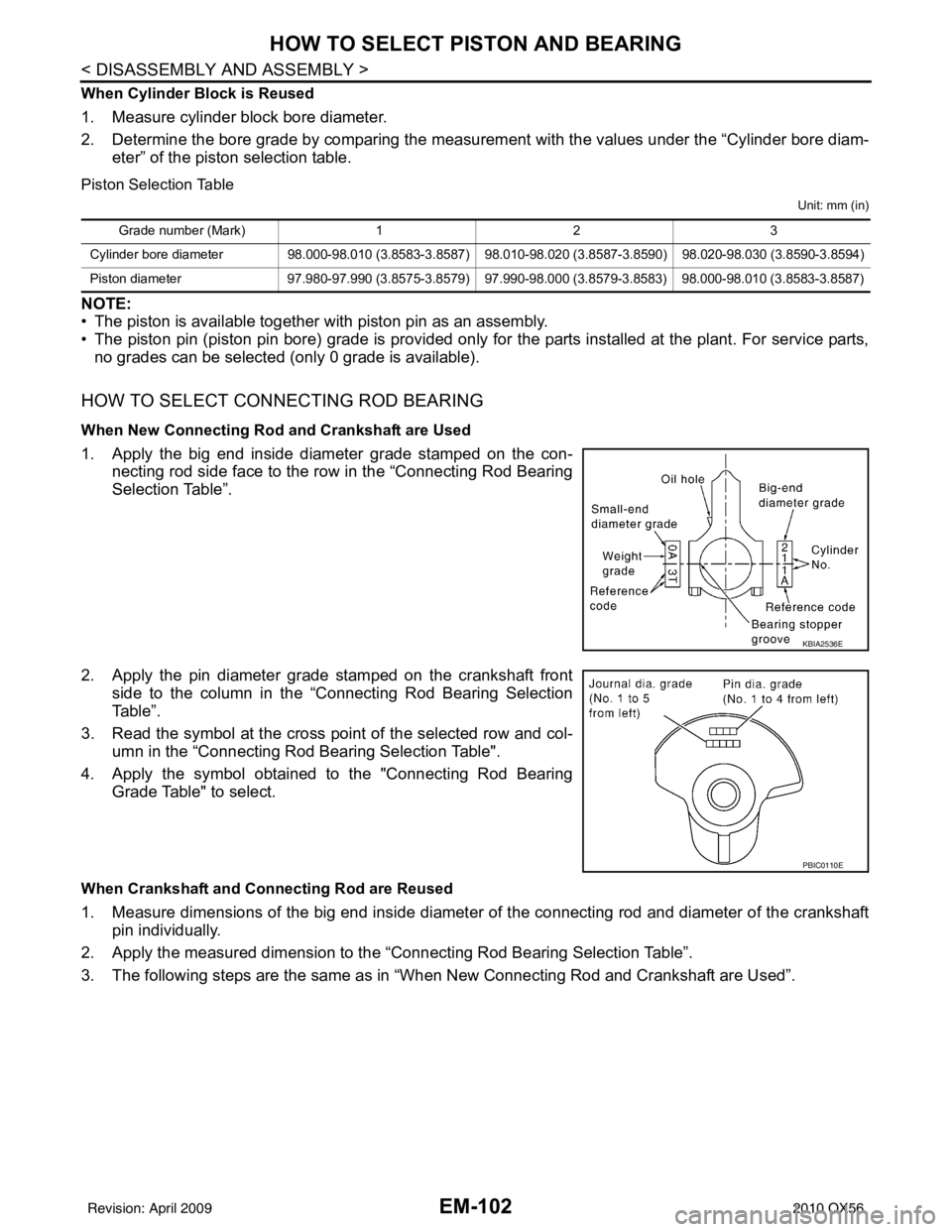
1. Apply the big end inside diameter grade stamped on the con-
necting rod side face to the row in the “Connecting Rod Bearing
Selection Table”.
2. Apply the pin diameter grade stamped on the crankshaft front side to the column in the “Connecting Rod Bearing Selection
Table”.
3. Read the symbol at the cross point of the selected row and col-
umn in the “Connecting Rod Bearing Selection Table".
4. Apply the symbol obtained to the "Connecting Rod Bearing Grade Table" to select.
When Crankshaft and Connecting Rod are Reused
1. Measure dimensions of the big end inside diameter of the connecting rod and diameter of the crankshaftpin individually.
2. Apply the measured dimension to the “Connecting Rod Bearing Selection Table”.
3. The following steps are the same as in “When New Connecting Rod and Crankshaft are Used”.
Grade number (Mark) 12 3
Cylinder bore diameter 98.000-98.010 (3.8583-3.8587) 98.010-98.020 (3.8587-3.8590) 98.020-98.030 (3.8590-3.8594)
Piston diameter 97.980-97.990 (3.8575-3.8579) 97.990-98.000 (3.8579-3.8583) 98.000-98.010 (3.8583-3.8587)
KBIA2536E
PBIC0110E
Revision: April 20092010 QX56
Page 1962 of 4210
SERVICE DATA AND SPECIFICATIONS (SDS)EM-111
< SERVICE DATA AND SPECIFICATIONS (SDS)
C
DE
F
G H
I
J
K L
M A
EM
NP
O
Unit: mm (in)
Spark Plug Tube
Unit: mm (in)
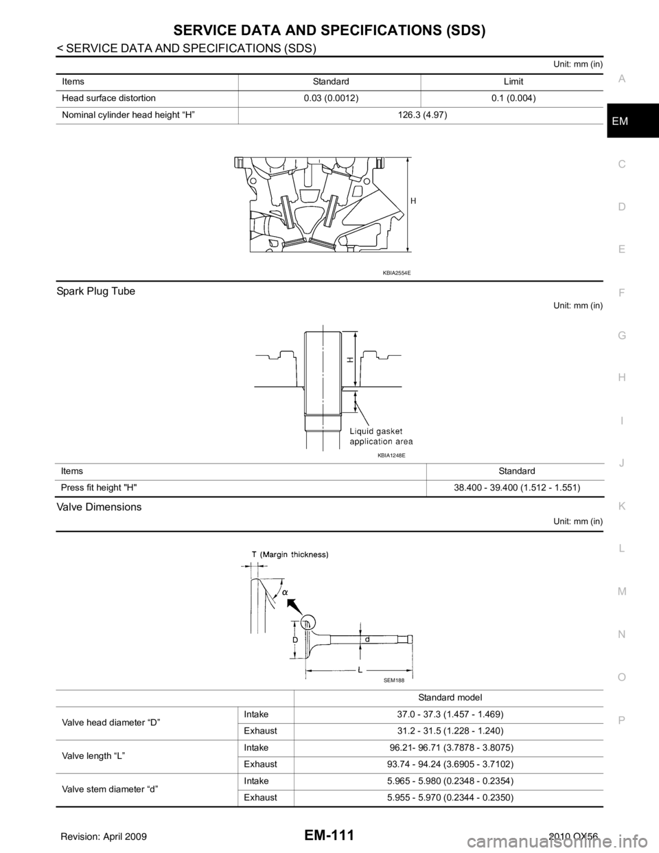
Valve Dimensions
Unit: mm (in)
Items
StandardLimit
Head surface distortion 0.03 (0.0012)0.1 (0.004)
Nominal cylinder head height “H” 126.3 (4.97)
KBIA2554E
Items Standard
Press fit height "H" 38.400 - 39.400 (1.512 - 1.551)
KBIA1248E
Standard model
Valve head diameter “D” Intake
37.0 - 37.3 (1.457 - 1.469)
Exhaust 31.2 - 31.5 (1.228 - 1.240)
Valve length “L” Intake
96.21- 96.71 (3.7878 - 3.8075)
Exhaust 93.74 - 94.24 (3.6905 - 3.7102)
Valve stem diameter “d” Intake
5.965 - 5.980 (0.2348 - 0.2354)
Exhaust 5.955 - 5.970 (0.2344 - 0.2350)
SEM188
Revision: April 20092010 QX56
Page 2224 of 4210
GI-1
GENERAL INFORMATION
C
DE
F
G H
I
J
K L
M B
GI
SECTION GI
N
O P
CONTENTS
GENERAL INFORMATION
HOW TO USE THIS MANU AL ......................3
HOW TO USE THIS MANUAL ....................... .....3
Description .......................................................... ......3
Terms ........................................................................3
Units ..........................................................................3
Contents ....................................................................3
Relation between Illustrations and Descriptions .......4
Components ..............................................................4
HOW TO FOLLOW TROUBLE DIAGNOSES .....6
Description ................................................................6
How to Follow Test Groups in Trouble Diagnosis ......6
Key to Symbols Signifying Measurements or Pro-
cedures ............................................................... ......
7
HOW TO READ WIRING DIAGRAMS ................9
Connector symbols ............................................. ......9
Sample/wiring diagram -example- ...........................10
Description ..............................................................11
ABBREVIATIONS .......................................... ....13
Abbreviation List .................................................. ....13
TIGHTENING TORQUE OF STANDARD
BOLTS ................................................................
14
Tightening Torque Table .........................................14
RECOMMENDED CHEMICAL PRODUCTS
AND SEALANTS ............................................ ....
15
Recommended Chemical Products and Sealants ....15
TERMINOLOGY .................................................16
SAE J1930 Terminology List ............................... ....16
FEATURES OF NEW MODEL .....................20
IDENTIFICATION INFORMATION .....................20
Model Variation ................................................... ....20
Identification Number ..............................................21
Identification Plate ...................................................22
Dimensions .............................................................23
Wheels & Tires .................................................... ....23
PRECAUTION ..............................................24
PRECAUTIONS .................................................24
Description ........................................................... ....24
Precaution for Supplemental Restraint System
(SRS) "AIR BAG" and "SEAT BELT PRE-TEN-
SIONER" .................................................................
24
Precaution Necessary for Steering Wheel Rota-
tion After Battery Disconnect ...................................
24
Procedures without Cowl Top Cover .......................25
General Precautions ................................................25
Three Way Catalyst .................................................27
Precaution for Fuel (Unleaded Premium Gasoline
Required) .................................................................
27
Multiport Fuel Injection System or Engine Control
System .....................................................................
27
Hoses ......................................................................27
Engine Oils ..............................................................28
Air Conditioning .......................................................29
LIFTING POINT .................................................30
Pantograph Jack ......................................................30
Garage Jack and Safety Stand ................................30
2-Pole Lift ................................................................30
TOW TRUCK TOWING .....................................32
Tow Truck Towing ...................................................32
Vehicle Recovery (Freeing a stuck vehicle) ............33
BASIC INSPECTION ...................................34
SERVICE INFORMATION FOR ELECTRICAL
INCIDENT ..........................................................
34
Work Flow ............................................................ ....34
Control Units and Electrical Parts ............................34
How to Check Terminal ...........................................35
Intermittent Incident ............................................. ....38
Circuit Inspection .....................................................41
CONSULT-III CHECKING SYSTEM .................46
Revision: April 20092010 QX56
Page 2246 of 4210
IDENTIFICATION INFORMATIONGI-23
< FEATURES OF NEW MODEL >
C
DE
F
G H
I
J
K L
M B
GI
N
O P
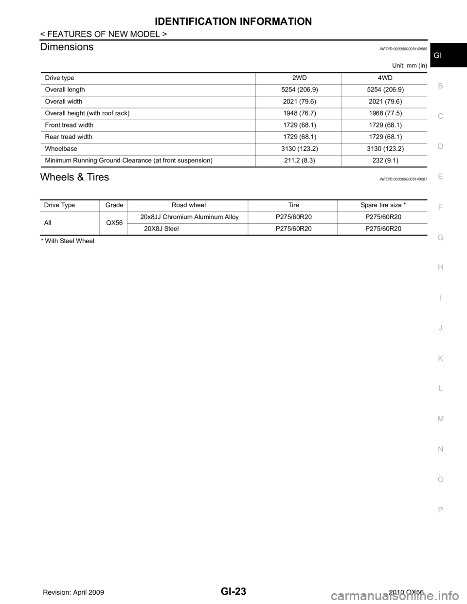
DimensionsINFOID:0000000005149586
Unit: mm (in)
Wheels & TiresINFOID:0000000005149587
* With Steel Wheel Drive type
2WD4WD
Overall length 5254 (206.9)5254 (206.9)
Overall width 2021 (79.6)2021 (79.6)
Overall height (with roof rack) 1948 (76.7)1968 (77.5)
Front tread width 1729 (68.1)1729 (68.1)
Rear tread width 1729 (68.1)1729 (68.1)
Wheelbase 3130 (123.2)3130 (123.2)
Minimum Running Ground Clearance (at front suspension) 211.2 (8.3)232 (9.1)
Drive Type Grade Road wheelTireSpare tire size *
All QX56 20x8JJ Chromium Aluminum Alloy
P275/60R20P275/60R20
20X8J Steel P275/60R20P275/60R20
Revision: April 20092010 QX56
Page 3950 of 4210
ASSEMBLYTM-255
< DISASSEMBLY AND ASSEMBLY >
CEF
G H
I
J
K L
M A
B
TM
N
O P
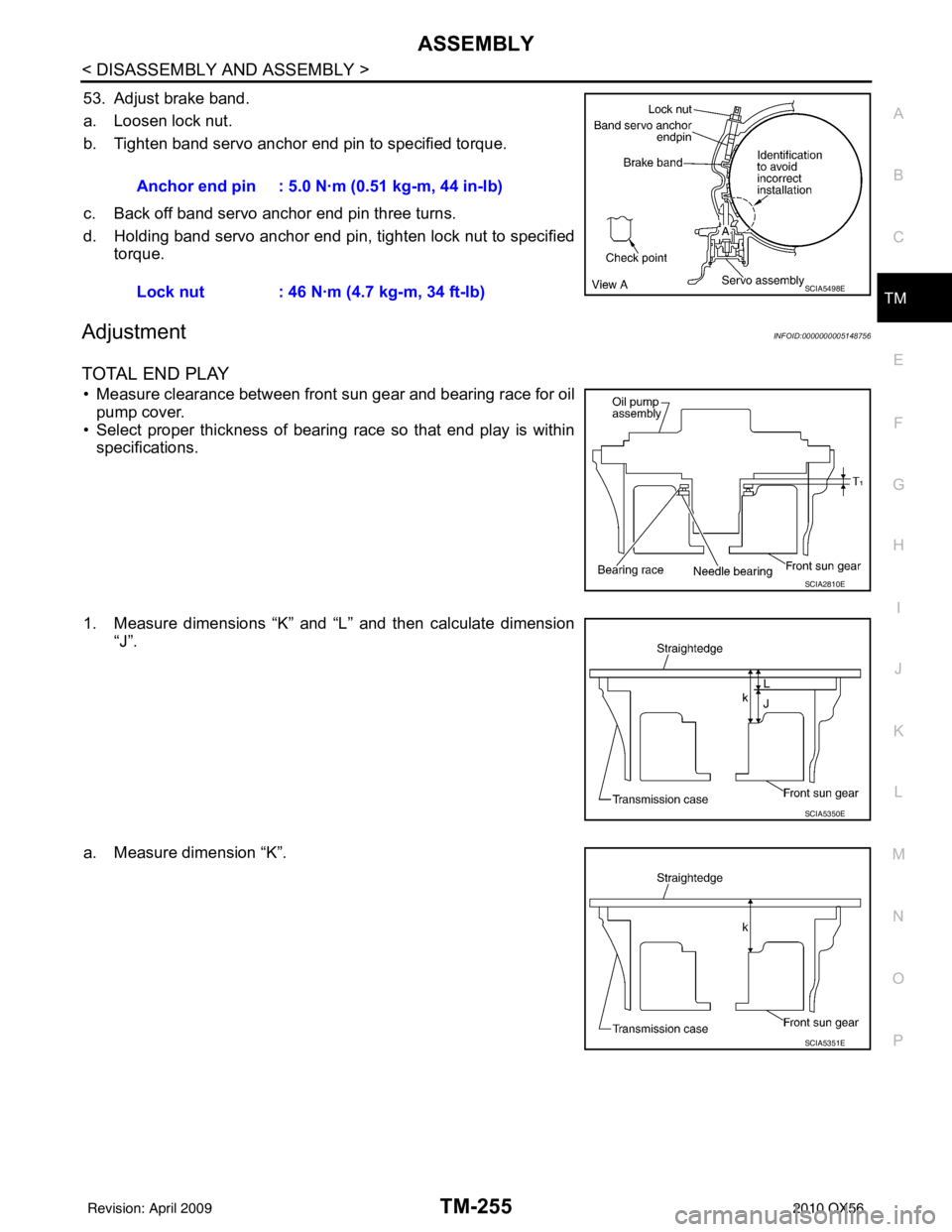
53. Adjust brake band.
a. Loosen lock nut.
b. Tighten band servo anchor end pin to specified torque.
c. Back off band servo anchor end pin three turns.
d. Holding band servo anchor end pin, tighten lock nut to specified torque.
AdjustmentINFOID:0000000005148756
TOTAL END PLAY
• Measure clearance between front sun gear and bearing race for oilpump cover.
• Select proper thickness of bearing race so that end play is within specifications.
1. Measure dimensions “K” and “L” and then calculate dimension “J”.
a. Measure dimension “K”. Anchor end pin : 5.0 N·m (0.51 kg-m, 44 in-lb)
Lock nut : 46 N·m (4.7 kg-m, 34 ft-lb)
SCIA5498E
SCIA2810E
SCIA5350E
SCIA5351E
Revision: April 20092010 QX56
Page 3951 of 4210
TM-256
< DISASSEMBLY AND ASSEMBLY >
ASSEMBLY
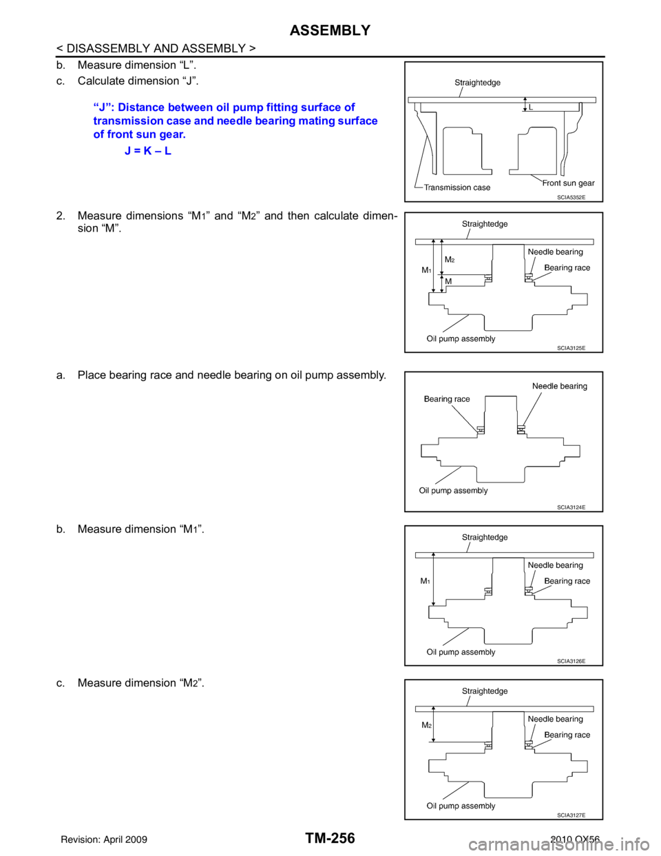
b. Measure dimension “L”.
c. Calculate dimension “J”.
2. Measure dimensions “M
1” and “M2” and then calculate dimen-
sion “M”.
a. Place bearing race and needle bearing on oil pump assembly.
b. Measure dimension “M
1”.
c. Measure dimension “M
2”.
“J”: Distance between oil pump fitting surface of
transmission case and needle
bearing mating surface
of front sun gear.
J = K – L
SCIA5352E
SCIA3125E
SCIA3124E
SCIA3126E
SCIA3127E
Revision: April 20092010 QX56