2010 INFINITI QX56 brake pads
[x] Cancel search: brake padsPage 484 of 4210

FRONT DISC BRAKEBR-39
< DISASSEMBLY AND ASSEMBLY >
C
DE
G H
I
J
K L
M A
B
BR
N
O P
FRONT DISC BRAKE
Disassembly and AssemblyINFOID:0000000005147923
DISASSEMBLY
1. Remove sliding pin bolts, and then remove the pads, sh ims, shim cover, and pad retainers from the torque
member.
2. Remove sliding pins and sliding pin boots from torque member.
3. Place a wooden block as shown, and blow air from union bolt hole to remove pistons and piston boots.
CAUTION:
Do not get your fingers caught in piston.
1. Sliding pin bolt 2. Bleed valve 3. Cap
4. Union bolt 5. Brake hose 6. Copper washer
7. Torque member bolt 8. Sliding pin boot 9. Torque member
10. Washers 11. Bushing 12. Sliding pin
13. Piston boot 14. Piston 15. Piston seal
16. Cylinder body Brake fluid1: Molykote M-77 grease
2: Rubber grease
AWFIA0573GB
BRB0032D
Revision: April 20092010 QX56
Page 486 of 4210

FRONT DISC BRAKEBR-41
< DISASSEMBLY AND ASSEMBLY >
C
DE
G H
I
J
K L
M A
B
BR
N
O P
3. Apply Molykote M-77 grease to piston boots. Cover the piston ends with piston boots, and then install cylinder side lip on piston
boots securely into the grooves on cylinder body.
CAUTION:
Do not reuse piston boots.
4. Apply clean brake fluid to pistons, then install pistons into cylin- der body and insert piston boot side lip into groove of pistons as
shown.
CAUTION:
Press the pistons evenly to prevent damage to cylinder
wall.
5. Apply rubber grease and insert into cylinder body by hand and insert piston bo\
ot piston-side lip into piston groove.
CAUTION:
Press pistons evenly and vary the pr essing point to prevent cylinder inner wall from being rubbed.
6. Apply rubber grease and install sliding pins, bushing and sliding pin boots to torque member.
7. Install the pads, shims, shim cover, and pad retainers from the torque member.
8. Install cylinder body. Tighten sliding pin bolts to the specified torque.
SFIA2432E
WFIA0211E
Revision: April 20092010 QX56
Page 487 of 4210

BR-42
< DISASSEMBLY AND ASSEMBLY >
REAR DISC BRAKE
REAR DISC BRAKE
Disassembly and AssemblyINFOID:0000000005147924
DISASSEMBLY
1. Remove pads from cylinder body.
2. Remove sliding sleeve and boot from cylinder body.
3. Place a wooden block as shown, and blow air into union bolthole to remove piston and piston boot.
CAUTION:
Do not get your fingers caught in piston.
1. Union bolt 2. Brake hose3. Copper washer
4. Cap 5. Bleed valve6. Sliding pin bolt
7. Cylinder body 8. Piston seal9. Piston
10. Piston boot 11. Knuckle slide12. Sliding sleeve boot
13. Sliding sleeve B. Brake fluidR. Rubber grease
M. Molykote M-77 Front
AWFIA0423GB
BRD0041D
Revision: April 20092010 QX56
Page 603 of 4210
![INFINITI QX56 2010 Factory Service Manual PRECAUTIONSBRC-111
< PRECAUTION > [VDC/TCS/ABS]
C
D
E
G H
I
J
K L
M A
B
BRC
N
O P
5. When the repair work is completed, return the ignition switch to the ″LOCK ″ position before connecting
the ba INFINITI QX56 2010 Factory Service Manual PRECAUTIONSBRC-111
< PRECAUTION > [VDC/TCS/ABS]
C
D
E
G H
I
J
K L
M A
B
BRC
N
O P
5. When the repair work is completed, return the ignition switch to the ″LOCK ″ position before connecting
the ba](/manual-img/42/57032/w960_57032-602.png)
PRECAUTIONSBRC-111
< PRECAUTION > [VDC/TCS/ABS]
C
D
E
G H
I
J
K L
M A
B
BRC
N
O P
5. When the repair work is completed, return the ignition switch to the ″LOCK ″ position before connecting
the battery cables. (At this time, the steering lock mechanism will engage.)
6. Perform a self-diagnosis check of al l control units using CONSULT-III.
Precaution for Brake SystemINFOID:0000000005148094
CAUTION:
• Always use recommended brake fluid. Refer to MA-13, "
Fluids and Lubricants".
• Never reuse drained brake fluid.
• Be careful not to splash brake fluid on painted areas; it may cause paint damage. If brake fluid is
splashed on painted areas, wash it away with water immediately.
• To clean or wash all parts of master cylin der and disc brake caliper, use clean brake fluid.
• Never use mineral oils such as gasoline or kerosen e. They will ruin rubber parts of the hydraulic sys-
tem.
• Use flare nut wrench when removing and installing brake
tube.
• If a brake fluid leak is found, the part must be disassembled
without fail. Then it has to be replaced with a new one if a
defect exists.
• Turn the ignition switch OFF and remove the connector of the ABS actuator and electric unit (con trol unit) or the battery ter-
minal before performing the work.
• Always torque brake lines when installing.
• Burnish the brake contact surf aces after refinishing or replac-
ing rotors, after replacing pads, or if a soft pedal occurs at
very low mileage.
Refer to BR-30, "
Brake Burnishing Procedure" (front disc brake) or BR-35, "Brake Burnishing Proce-
dure" (rear disc brake).
WARNING:
• Clean brake pads and shoes with a waste cl oth, then wipe with a dust collector.
Precaution for Brake ControlINFOID:0000000005148095
• During ABS operation, the brake pedal may vibrate lightly and a mechanical noise may be heard. This is
normal.
• Just after starting vehicle, the brake pedal may vibrate or a motor operating noise may be heard from engine
compartment. This is a normal status of operation check.
• Stopping distance may be longer than that of vehicles without ABS when vehicle drives on rough, gravel, or snow-covered (fresh, deep snow) roads.
• When an error is indicated by ABS or another warning lamp, collect all necessary information from customer (what symptoms are present under what conditions) and check for simple causes before starting diagnosis.
Besides electrical system inspection, check boos ter operation, brake fluid level, and fluid leaks.
• If incorrect tire sizes or types are installed on the vehicle or brake pads are not Genuine NISSAN parts, stop-
ping distance or steering stability may deteriorate.
• If there is a radio, antenna or related wiring near control module, ABS function may have a malfunction or
error.
• If aftermarket parts (car stereo, CD player, etc.) have been installed, check for incidents such as harness pinches, open circuits or improper wiring.
• If the following components are replaced with non-genuine components or modified, the VDC OFF indicator lamp and SLIP indicator lamp may turn on or the VDC system may not operate properly. Components
related to suspension (shock absorbers, struts, springs , bushings, etc.), tires, wheels (exclude specified
size), components related to brake system (pads, roto rs, calipers, etc.), components related to engine (muf-
fler, ECM, etc.), components related to body reinforcement (roll bar, tower bar, etc.).
• Driving with broken or excessively worn suspensi on components, tires or brake system components may
cause the VDC OFF indicator lamp and the SLIP indicator lamp to turn on, and the VDC system may not
operate properly.
• When the TCS or VDC is activated by sudden acceleration or sudden turn, some noise may occur. The noise is a result of the normal operation of the TCS and VDC.
• When driving on roads which have extreme slopes (such as mountainous roads) or high banks (such as sharp curves on a freeway), the VDC may not operate no rmally, or the VDC warning lamp and the SLIP indi-
cator lamp may turn on. This is not a problem if normal operation can be resumed after restarting the engine.
SBR686C
Revision: April 20092010 QX56
Page 2555 of 4210

SQUEAK AND RATTLE TROUBLE DIAGNOSESINT-3
< SYMPTOM DIAGNOSIS >
C
DE
F
G H
I
K L
M A
B
INT
N
O P
If possible, drive the vehicle with the customer until the noise is duplicated. Note any additional information on
the Diagnostic Worksheet regarding the conditions or lo cation of the noise. This information can be used to
duplicate the same conditions when you confirm the repair.
If the noise can be duplicated easily during the test drive, to help identify the source of the noise, try to dupli-
cate the noise with the vehicle stopped by doing one or all of the following:
1) Close a door.
2) Tap or push/pull around the area where the noise appears to be coming from.
3) Rev the engine.
4) Use a floor jack to recreate vehicle “twist”.
5) At idle, apply engine load. With brakes applied, place A/T shift selector in drive position.
6) Raise the vehicle on a hoist and hit a tire with a rubber hammer.
• Drive the vehicle and attempt to duplicate the conditions the customer states exist when the noise occurs.
• If it is difficult to duplicate the noise, drive the vehicle slowly on an undulating or rough road to stress the
vehicle body.
CHECK RELATED SERVICE BULLETINS
After verifying the customer concern or symptom, check ASIST for Technical Service Bulletins (TSBs) related
to that concern or symptom.
If a TSB relates to the symptom, follow the procedure to repair the noise.
LOCATE THE NOISE AND IDENTIFY THE ROOT CAUSE
1. Narrow down the noise to a general area.To help pinpoint the source of the noise, use a listening tool (Chassis Ear: J-39570, Engine Ear: J-39565 and mechanic's stethoscope).
2. Narrow down the noise to a more specific area and identify the cause of the noise by:
• removing the components in the area that you suspect the noise is coming from. Do not use too much force when removing clips and fasteners, otherwise clips and fasteners can be broken
or lost during the repair, resulting in the creation of new noise.
• tapping or pushing/pulling the component that you suspect is causing the noise.
Do not tap or push/pull the component with excessive force, otherwise the noise will be eliminated only tem-
porarily.
• feeling for a vibration with your hand by touching the component(s) that you suspect is (are) causing the
noise.
• placing a piece of paper between components that you suspect are causing the noise.
• looking for loose components and contact marks. Refer to INT-4, "
Generic Squeak and Rattle Troubleshooting".
REPAIR THE CAUSE
• If the cause is a loose component, tighten the component securely.
• If the cause is insufficient clearance between components:
- separate components by repositioning or loos ening and retightening the component, if possible.
- insulate components with a suitable insulator such as urethane pads, foam blocks, felt cloth tape or urethane tape. A NISSAN Squeak and Rattle Kit (J-43980) is available through your authorized NISSAN Parts Depart-
ment.
CAUTION:
Do not use excessive force as many components are constructed of plastic and may be damaged.
Always check with the Parts Department for the latest parts information.
The following materials are contained in the NISSAN Squeak and Rattle Kit (J-43980). Each item can be
ordered separately as needed.
URETHANE PADS [1.5 mm (0.059 in) thick]
Insulates connectors, harness, etc.
76268-9E005: 100 ×135 mm (3.94 ×5.31 in)/76884-71L01: 60 ×85 mm (2.36× 3.35 in)/76884-71L02: 15× 25
mm (0.59 ×0.98 in)
INSULATOR (Foam blocks)
Insulates components from contact. Can be used to fill space behind a panel.
73982-9E000: 45 mm (1.77 in) thick, 50× 50 mm (1.97×1.97 in)/73982-50Y00: 10 mm (0.39 in) thick,
50× 50 mm (1.97 ×1.97 in)
INSULATOR (Light foam block)
80845-71L00: 30 mm (1.18 in) thick, 30 ×50 mm (1.18 ×1.97 in)
FELT CLOTH TAPE
Used to insulate where movement does not occu r. Ideal for instrument panel applications.
Revision: April 20092010 QX56
Page 2579 of 4210

IP-6
< SYMPTOM DIAGNOSIS >
SQUEAK AND RATTLE TROUBLE DIAGNOSES
If possible, drive the vehicle with the customer until the noise is duplicated. Note any additional information on
the Diagnostic Worksheet regarding the conditions or lo cation of the noise. This information can be used to
duplicate the same conditions when you confirm the repair.
If the noise can be duplicated easily during the test drive, to help identify the source of the noise, try to dupli-
cate the noise with the vehicle stopped by doing one or all of the following:
1) Close a door.
2) Tap or push/pull around the area where the noise appears to be coming from.
3) Rev the engine.
4) Use a floor jack to recreate vehicle “twist”.
5) At idle, apply engine load. With brakes appllied, place A/T shift selector in drive position.
6) Raise the vehicle on a hoist and hit a tire with a rubber hammer.
• Drive the vehicle and attempt to duplicate the conditions the customer states exist when the noise occurs.
• If it is difficult to duplicate the noise, drive the v ehicle slowly on an undulating or rough road to stress the
vehicle body.
CHECK RELATED SERVICE BULLETINS
After verifying the customer concern or symptom, chec k ASIST for Technical Service Bulletins (TSBs) related
to that concern or symptom.
If a TSB relates to the symptom, follo w the procedure to repair the noise.
LOCATE THE NOISE AND IDENTIFY THE ROOT CAUSE
1. Narrow down the noise to a general area. To help pi npoint the source of the noise, use a listening tool
(Chassis Ear: J-39570, Engine Ear and mechanics stethoscope).
2. Narrow down the noise to a more specific area and identify the cause of the noise by:
• removing the components in the area that you suspect the noise is coming from.
Do not use too much force when removing clips and fasteners, otherwise clips and fastener can be broken
or lost during the repair, resulting in the creation of new noise.
• tapping or pushing/pulling the component that you suspect is causing the noise.
Do not tap or push/pull the component with excessive force, otherwise the noise will be eliminated only tem-
porarily.
• feeling for a vibration with your hand by touching the component(s) that you suspect is (are) causing the
noise.
• placing a piece of paper between components that you suspect are causing the noise.
• looking for loose components and contact marks. Refer to IP-7, "
Generic Squeak and Rattle Troubleshooting".
REPAIR THE CAUSE
• If the cause is a loose component, tighten the component securely.
• If the cause is insufficient clearance between components:
- separate components by repositioning or loos ening and retightening the component, if possible.
- insulate components with a suitable insulator such as urethane pads, foam blocks, felt cloth tape or urethane tape. A Nissan Squeak and Rattle Kit (J-43980) is available through your authorized Nissan Parts Depart-
ment.
CAUTION:
Do not use excessive force as many components are constructed of plastic and may be damaged.
NOTE:
Always check with the Parts Departm ent for the latest parts information.
The following materials are contained in the Nissan Squeak and Rattle Kit (J-43980). Each item can be
ordered separately as needed.
URETHANE PADS [1.5 mm (0.059 in) thick]
Insulates connectors, harness, etc.
76268-9E005: 100 ×135 mm (3.94 ×5.31 in)/76884-71L01: 60 ×85 mm (2.36 ×3.35 in)/76884-
71L02: 15 ×25 mm (0.59 ×0.98 in)
INSULATOR (Foam blocks)
Insulates components from contact. Can be used to fill space behind a panel.
73982-9E000: 45 mm (1.77 in) thick, 50 ×50 mm (1.97 ×1.97 in)/73982-
50Y00: 10 mm (0.39 in) thick, 50 ×50 mm (1.97 ×1.97 in)
INSULATOR (Light foam block)
80845-71L00: 30 mm (1.18 in) thick, 30 ×50 mm (1.18 ×1.97 in)
FELT CLOTHTAPE
Used to insulate where movement does not occu r. Ideal for instrument panel applications.
Revision: April 20092010 QX56
Page 2713 of 4210

PERIODIC MAINTENANCEMA-9
< ON-VEHICLE MAINTENANCE >
C
DE
F
G H
I
J
K L
M B
MA
N
O A
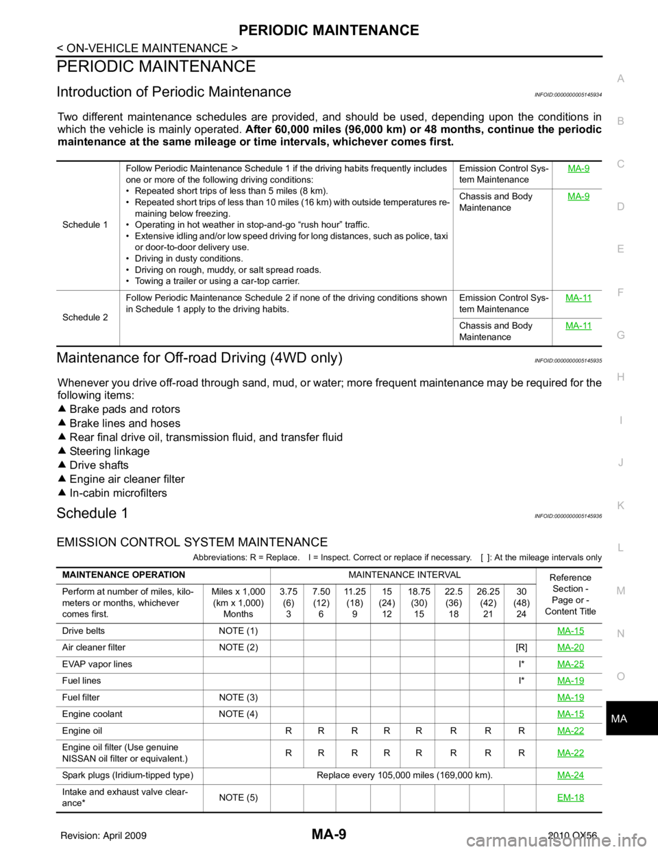
PERIODIC MAINTENANCE
Introduction of Periodic MaintenanceINFOID:0000000005145934
Two different maintenance schedules are provi
ded, and should be used, depending upon the conditions in
which the vehicle is mainly operated. After 60,000 miles (96,000 km) or 48 months, continue the periodic
maintenance at the same mileage or ti me intervals, whichever comes first.
Maintenance for Off-road Driving (4WD only)INFOID:0000000005145935
Whenever you drive off-road through sand, mud, or wa ter; more frequent maintenance may be required for the
following items:
Brake pads and rotors
Brake lines and hoses
Rear final drive oil, transmission fluid, and transfer fluid
Steering linkage
Drive shafts
Engine air cleaner filter
In-cabin microfilters
Schedule 1INFOID:0000000005145936
EMISSION CONTROL SYSTEM MAINTENANCE
Abbreviations: R = Replace. I = Ins pect. Correct or replace if necessary. [ ]: At the mileage intervals only
Schedule 1Follow Periodic Maintenance Schedule 1 if the driving habits frequently includes
one or more of the following driving conditions:
• Repeated short trips of less than 5 miles (8 km).
• Repeated short trips of less than 10 miles (16 km) with outside temperatures re-
maining below freezing.
• Operating in hot weather in stop-and-go “rush hour” traffic.
• Extensive idling and/or low speed driving for long distances, such as police, taxi
or door-to-door delivery use.
• Driving in dusty conditions.
• Driving on rough, muddy, or salt spread roads.
• Towing a trailer or using a car-top carrier. Emission Control Sys-
tem Maintenance
MA-9
Chassis and Body
Maintenance
MA-9
Schedule 2Follow Periodic Maintenance Schedule 2 if none of the driving conditions shown
in Schedule 1 apply to the driving habits.
Emission Control Sys-
tem MaintenanceMA-11Chassis and Body
Maintenance
MA-11
MAINTENANCE OPERATION
MAINTENANCE INTERVAL
Reference
Section -
Page or -
Content Title
Perform at number of miles, kilo-
meters or months, whichever
comes first. Miles x 1,000
(km x 1,000) Months 3.75
(6)3 7.50
(12) 6 11 . 2 5
(18) 9 15
(24) 12 18.75
(30)15 22.5
(36) 18 26.25
(42)21 30
(48) 24
Drive belts NOTE (1) MA-15
Air cleaner filterNOTE (2) [R]MA-20
EVAP vapor lines I*MA-25
Fuel lines I*MA-19
Fuel filter NOTE (3) MA-19
Engine coolantNOTE (4) MA-15
Engine oilR R R R R R R R MA-22
Engine oil filter (Use genuine
NISSAN oil filter or equivalent.)RR RRR R R R
MA-22
Spark plugs (Iridium-tipped type)Replace every 105,000 miles (169,000 km).MA-24
Intake and exhaust valve clear-
ance*NOTE (5)
EM-18
Revision: April 20092010 QX56
Page 2714 of 4210

MA-10
< ON-VEHICLE MAINTENANCE >
PERIODIC MAINTENANCE
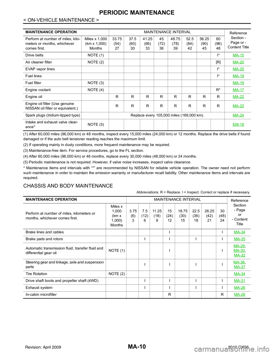
(1) After 60,000 miles (96,000 km) or 48 months, inspect every 15,000 miles (24,000 km) or 12 months. Replace the drive belts if found
damaged or if the auto belt tensioner reading reaches the maximum limit.
(2) If operating mainly in dusty conditions, more frequent maintenance may be required.
(3) Maintenance-free item. For service procedures, go to the FL section.
(4) After 60,000 miles (96,000 km) or 48 months, replace every 30,000 miles (48,000 km) or 24 months.
(5) Periodic maintenance is not required. However, if valve noise increases, inspect valve clearance.
* Maintenance items and intervals with “*” are recommended by NISSAN for reliable vehicle operation. The owner need not perform
such maintenance in order to maintain the emission warranty or manufacturer recall liability. Other maintenance items and intervals are
required.
CHASSIS AND BODY MAINTENANCE
Abbreviations: R = Replace. I = Inspec t. Correct or replace if necessary.
MAINTENANCE OPERATION MAINTENANCE INTERVAL
Reference
Section -
Page or -
Content Title
Perform at number of miles, kilo-
meters or months, whichever
comes first. Miles x 1,000
(km x 1,000) Months 33.75
(54)27 37.5
(60) 30 41.25
(66)33 45
(72) 36 48.75
(78)39 52.5
(84) 42 56.25
(90)45 60
(96) 48
Drive belts NOTE (1) I*MA-15
Air cleaner filter NOTE (2) [R]MA-20
EVAP vapor lines I*MA-25
Fuel lines I*MA-19
Fuel filter NOTE (3) MA-19
Engine coolantNOTE (4) R*MA-17
Engine oil R R R R R R R R MA-22
Engine oil filter (Use genuine
NISSAN oil filter or equivalent.)R R RRRRRR
MA-22
Spark plugs (Iridium-tipped type)Replace every 105,000 miles (169,000 km).MA-24
Intake and exhaust valve clear-
ance*NOTE (5)
EM-18
MAINTENANCE OPERATIONMAINTENANCE INTERVAL
Reference
Section- Page or
- Content Title
Perform at number of miles, kilometers or
months, whichever comes first. Miles x
1,000
(km x
1,000)
Months 3.75
(6)3 7.5
(12) 6 11 . 2 5
(18) 9 15
(24) 12 18.75
(30)15 22.5
(36) 18 26.25
(42)21 30
(48) 24
Brake lines and cables IIMA-34
Brake pads and rotors II I IMA-35
Automatic transmission fluid, transfer fluid and
differential gear oil NOTE (1)
IIMA-29,
MA-30
,
MA-32
Steering gear and linkage, axle and suspension
parts II I I
MA-36,
MA-37
Tire Rotation NOTE (2) MA-34
Drive shaft boots and propeller shaft (4WD)II I IMA-31
Exhaust system II I IMA-26
In-cabin microfilter RRMA-26
Revision: April 20092010 QX56