2010 INFINITI QX56 battery replacement
[x] Cancel search: battery replacementPage 2296 of 4210
HA-4
< PRECAUTION >
PRECAUTIONS
5. When the repair work is completed, return the ignition switch to the ″LOCK ″ position before connecting
the battery cables. (At this time, the steering lock mechanism will engage.)
6. Perform a self-diagnosis check of a ll control units using CONSULT-III.
Precaution for Working with HFC-134a (R-134a)INFOID:0000000005147630
WARNING:
• CFC-12 (R-12) refrigerant and HFC-134a (R-134a) refr igerant are not compatible. If the refrigerants
are mixed compressor failure is likely to occur. Refer to HA-4, "
Contaminated Refrigerant". To deter-
mine the purity of HFC-134a (R-134a) in the vehicle and recovery tank, use recovery/recycling equip-
ment and refrigerant identifier.
• Use only specified oil for the HFC-134a (R-134a) A/C system and HFC-134a (R-134a) components. If
oil other than that specified is used, compressor failure is likely to occur.
• The specified HFC-134a (R-134a) oi l rapidly absorbs moisture from the atmosphere. The following
handling precautions must be observed:
- When removing refrigerant components from a vehicle, immediately cap (seal) the component to
minimize the entry of moisture from the atmosphere.
- When installing refrigerant co mponents to a vehicle, do not remove the caps (unseal) until just
before connecting the components. Connect all refrigerant loop components as quickly as possible
to minimize the entry of moisture into system.
- Only use the specified oil from a sealed container. Immediately reseal containers of oil. Without
proper sealing, oil will become moisture saturat ed and should not be used.
- Avoid breathing A/C refrigerant and oil vapor or mist. Exposure may irrita te eyes, nose and throat.
Remove HFC-134a (R-134a) from the A/C system usin g certified service equipment meeting require-
ments of SAE J2210 [HFC-134a (R-134a) recycling equipment], or J2209 [HFC-134a (R-134a) recovery
equipment]. If accidental system discharge occurs, ventilate work area before resuming service.
Additional health and safety in formation may be obtained from refrigerant and oil manufacturers.
- Do not allow A/C oil to come in contact with styrofoam parts. Damage may result.
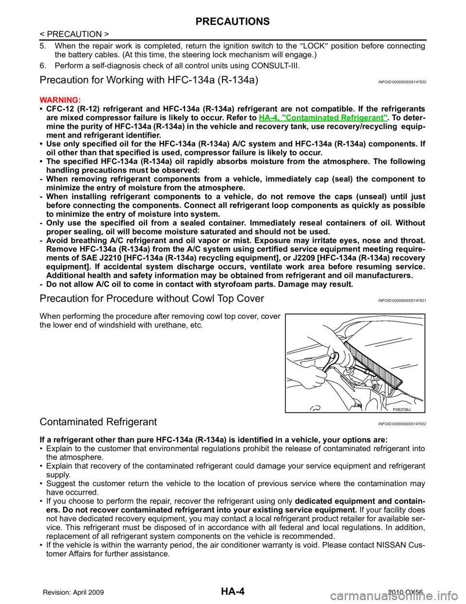
Precaution for Procedure without Cowl Top CoverINFOID:0000000005147631
When performing the procedure after removing cowl top cover, cover
the lower end of windshield with urethane, etc.
Contaminated RefrigerantINFOID:0000000005147632
If a refrigerant other than pure HFC-134a (R-134a) is identified in a vehicle, your options are:
• Explain to the customer that environmental regulations prohibit the release of contaminated refrigerant into
the atmosphere.
• Explain that recovery of the contaminated refri gerant could damage your service equipment and refrigerant
supply.
• Suggest the customer return the vehicle to the location of previous service where the contamination may have occurred.
• If you choose to perform the repair, recover the refrigerant using only dedicated equipment and contain- ers. Do not recover contamin ated refrigerant into your existing service equipment. If your facility does
not have dedicated recovery equipment, you may contact a local refrigerant product retailer for available ser-
vice. This refrigerant must be disposed of in acco rdance with all federal and local regulations. In addition,
replacement of all refrigerant system components on the vehicle is recommended.
• If the vehicle is within the warranty period, the air conditioner warranty is void. Please contact NISSAN Cus- tomer Affairs for further assistance.
PIIB3706J
Revision: April 20092010 QX56
Page 2705 of 4210
MA-1
MAINTENANCE
C
DE
F
G H
I
J
K L
M B
MA
SECTION MA
N
O A
CONTENTS
MAINTENANCE
PRECAUTION .......
........................................3
PRECAUTIONS .............................................. .....3
Precaution for Supplemental Restraint System
(SRS) "AIR BAG" and "SEAT BELT PRE-TEN-
SIONER" ............................................................. ......
3
Precaution Necessary for Steering Wheel Rota-
tion After Battery Disconnect ............................... ......
3
PREPARATION ............................................5
PREPARATION .............................................. .....5
Special Service Tool ........................................... ......5
Commercial Service Tool ..........................................5
ON-VEHICLE MAINTENANCE .....................6
GENERAL MAINTE NANCE ........................... .....6
General Maintenance .......................................... ......6
PERIODIC MAINTENANCE ................................9
Introduction of Periodic Maintenance .................. ......9
Maintenance for Off-road Driving (4WD only) ...........9
Schedule 1 ................................................................9
Schedule 2 ..............................................................11
RECOMMENDED FLUIDS AND LUBRI-
CANTS ................................................................
13
Fluids and Lubricants .......................................... ....13
Engine Oil Recommendation ..................................14
ENGINE MAINTENANCE ...................................15
DRIVE BELTS ....................................................... ....15
DRIVE BELTS : Exploded View ..............................15
DRIVE BELTS : Checking Drive Belts ....................15
ENGINE COOLANT ............................................... ....15
ENGINE COOLANT : Inspection .............................15
ENGINE COOLANT : Changing Engine Coolant ....17
FUEL LINES .......................................................... ....19
FUEL LINES : Checking Fuel Line ..........................19
FUEL FILTER ......................................................... ....19
FUEL FILTER : Changing Fuel Filter .......................19
AIR CLEANER FILTER ......................................... ....19
AIR CLEANER FILTER : Exploded View ................20
AIR CLEANER FILTER : Removal and Installation
(Viscous paper type) ................................................
20
ENGINE OIL ........................................................... ....20
ENGINE OIL : Inspection .........................................20
ENGINE OIL : Changing Engine Oil ........................22
OIL FILTER ............................................................ ....22
OIL FILTER : Removal and Installation ...................22
SPARK PLUG ........................................................ ....23
SPARK PLUG : Exploded View ...............................24
SPARK PLUG : Removal and Installation ...............24
EVAP VAPOR LINES ............................................ ....25
EVAP VAPOR LINES : Checking EVAP Vapor
Line ..........................................................................
25
CHASSIS AND BODY MAINTENANCE ...........26
IN-CABIN MICROFILTER ...................................... ....26
IN-CABIN MICROFILTER : Removal and Installa-
tion ....................................................................... ....
26
EXHAUST SYSTEM ...................................................26
EXHAUST SYSTEM : Checking Exhaust System ....26
A/T FLUID .............................................................. ....27
A/T FLUID : Checking the A/T Fluid (ATF) ..............27
A/T FLUID : Changing the A/T Fluid (ATF) ..............29
TRANSFER FLUID ................................................ ....30
TRANSFER FLUID : Replacement ..........................30
TRANSFER FLUID : Inspection ..............................30
PROPELLER SHAFT ............................................. ....31
PROPELLER SHAFT : Checking Propeller Shaft ....31
DIFFERENTIAL GEAR OIL ................................... ....31
Revision: April 20092010 QX56
Page 3533 of 4210
SR-10
< ON-VEHICLE REPAIR >
FRONT PASSENGER AIR BAG MODULE
FRONT PASSENGER AIR BAG MODULE
Removal and InstallationINFOID:0000000005147759
The passenger air bag module originally installed in the vehicle uses direct-connect style harness connectors.
Service replacement passenger air bag modules use tab-locking style harness connectors. If the passenger
air bag module is replaced or if the direct-connect harness connectors are damaged, the vehicle wiring har-
ness must be modified to allow connection of the service replacement passenger air bag module. Follow the
wiring harness modification procedure within this section.
REMOVAL
CAUTION:
• Do not attempt to repair or replace damaged di rect-connect front passenger air bag module connec-
tors. If a direct-connect harness connector is damaged, the front passenger air bag must be
replaced and the wiri ng harness modified.
• Before servicing SRS, turn the ig nition switch off, disconnect both battery terminals and wait at least
three minutes.
• Always work from the side of or under front passenger air bag module.
1. Disconnect both the negative and positive battery terminals, then wait at least three minutes.
2. Remove the glove box. Refer to IP-17, "
Exploded View".
3. Remove two nuts (through glove box opening) retaining front passenger air bag module to instrument panel crossmember.
4. Disconnect the air bag module electrical connectors. • For removal/installation of the direct-connect SRS connectors, refer to SRC-9, "
Direct-connect SRS
Component Connectors".
5. Remove the instrument panel assembly from the vehicle. Refer to IP-12, "
Removal and Installation".
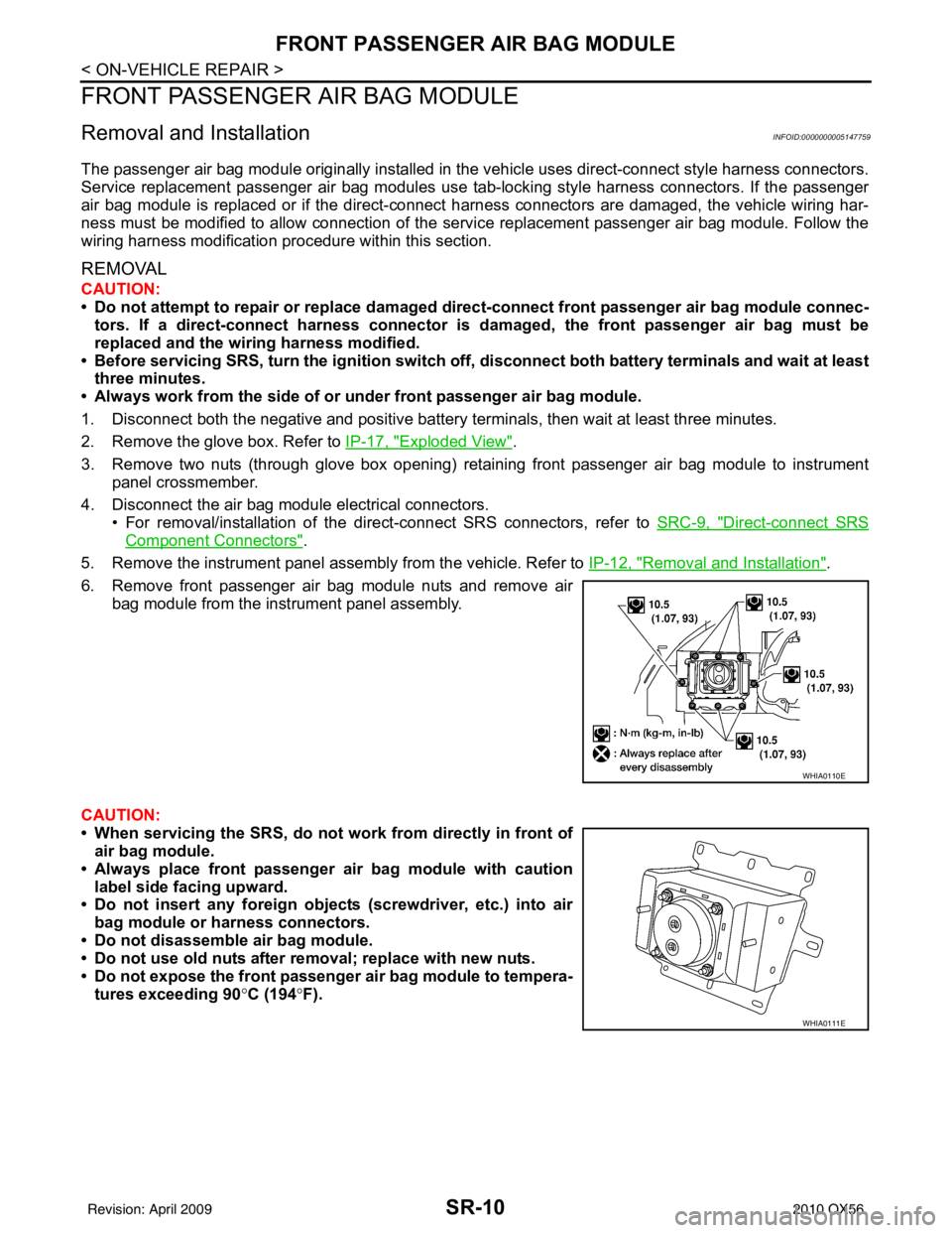
6. Remove front passenger air bag module nuts and remove air bag module from the instrument panel assembly.
CAUTION:
• When servicing the SRS, do not work from directly in front of
air bag module.
• Always place front passenger air bag module with caution label side facing upward.
• Do not insert any foreign object s (screwdriver, etc.) into air
bag module or harness connectors.
• Do not disassemble air bag module.
• Do not use old nuts after removal; replace with new nuts.
• Do not expose the front passenger air bag module to tempera- tures exceeding 90 °C (194 °F).
WHIA0110E
WHIA0111E
Revision: April 20092010 QX56
Page 3534 of 4210
FRONT PASSENGER AIR BAG MODULESR-11
< ON-VEHICLE REPAIR >
C
DE
F
G
I
J
K L
M A
B
SR
N
O P
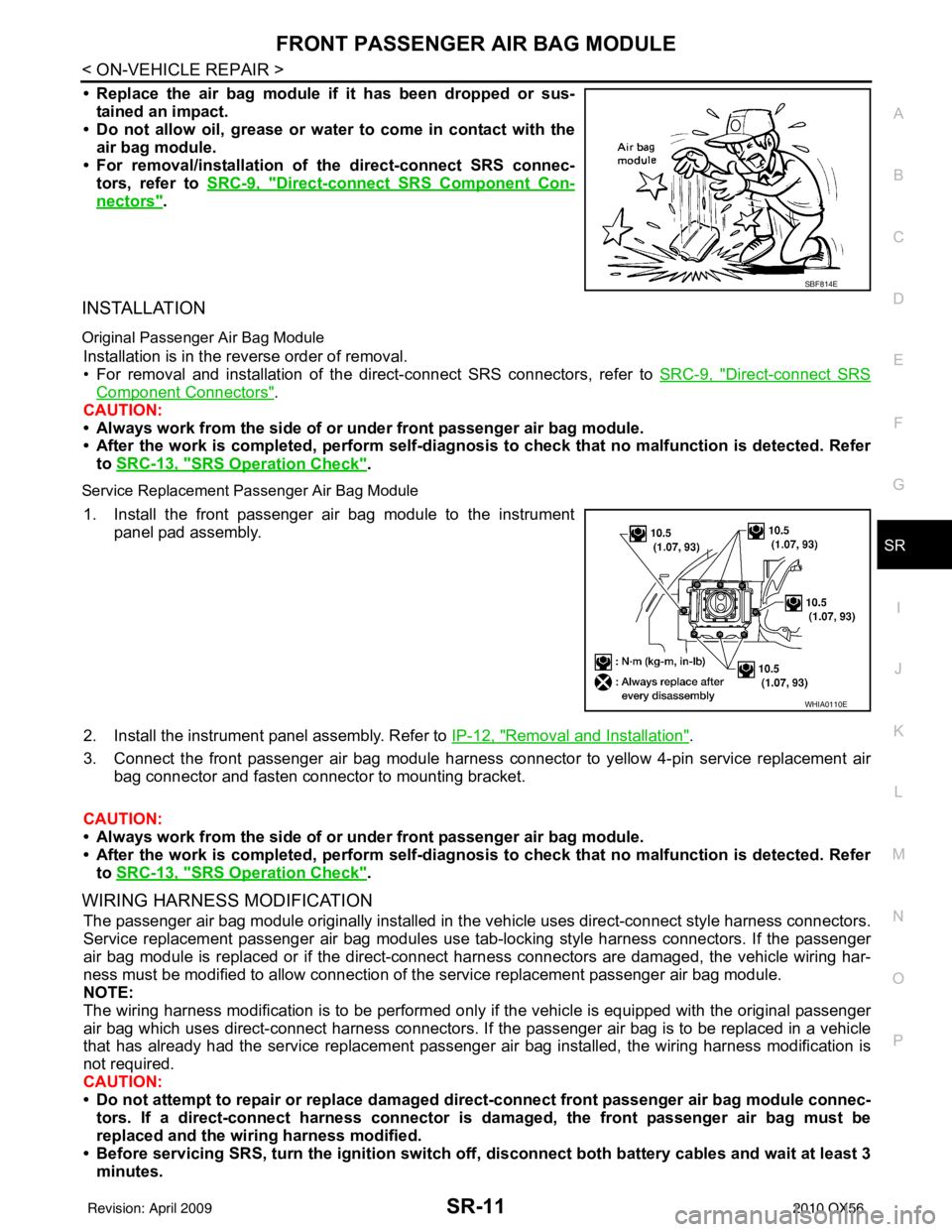
• Replace the air bag module if it has been dropped or sus-
tained an impact.
• Do not allow oil, grease or water to come in contact with the
air bag module.
• For removal/installation of the direct-connect SRS connec- tors, refer to SRC-9, "
Direct-connect SRS Component Con-
nectors".
INSTALLATION
Original Passenger Air Bag Module
Installation is in the reverse order of removal.
• For removal and installation of the direct-connect SRS connectors, refer to SRC-9, "
Direct-connect SRS
Component Connectors".
CAUTION:
• Always work from the side of or under front passenger air bag module.
• After the work is completed, perform self-diagnosi s to check that no malfunction is detected. Refer
to SRC-13, "
SRS Operation Check".
Service Replacement Passenger Air Bag Module
1. Install the front passenger air bag module to the instrument
panel pad assembly.
2. Install the instrument panel assembly. Refer to IP-12, "
Removal and Installation".
3. Connect the front passenger air bag module harness connector to yellow 4-pin service replacement air bag connector and fasten connector to mounting bracket.
CAUTION:
• Always work from the side of or under front passenger air bag module.
• After the work is completed, perform self-diagnosi s to check that no malfunction is detected. Refer
to SRC-13, "
SRS Operation Check".
WIRING HARNESS MODIFICATION
The passenger air bag module originally installed in t he vehicle uses direct-connect style harness connectors.
Service replacement passenger air bag modules use t ab-locking style harness connectors. If the passenger
air bag module is replaced or if the direct-connect harness connectors are damaged, the vehicle wiring har-
ness must be modified to allow connection of t he service replacement passenger air bag module.
NOTE:
The wiring harness modification is to be performed only if the vehicle is equipped with the original passenger
air bag which uses direct-connect harness connectors. If the passenger air bag is to be replaced in a vehicle
that has already had the service replacement passenger air bag installed, the wiring harness modification is
not required.
CAUTION:
• Do not attempt to repair or replace damaged dir ect-connect front passenger air bag module connec-
tors. If a direct-connect harness connector is damaged, the front passenger air bag must be
replaced and the wiri ng harness modified.
• Before servicing SRS, turn the igni tion switch off, disconnect both battery cables and wait at least 3
minutes.
SBF814E
WHIA0110E
Revision: April 20092010 QX56
Page 3536 of 4210
SIDE CURTAIN AIR BAG MODULESR-13
< ON-VEHICLE REPAIR >
C
DE
F
G
I
J
K L
M A
B
SR
N
O P
SIDE CURTAIN AIR BAG MODULE
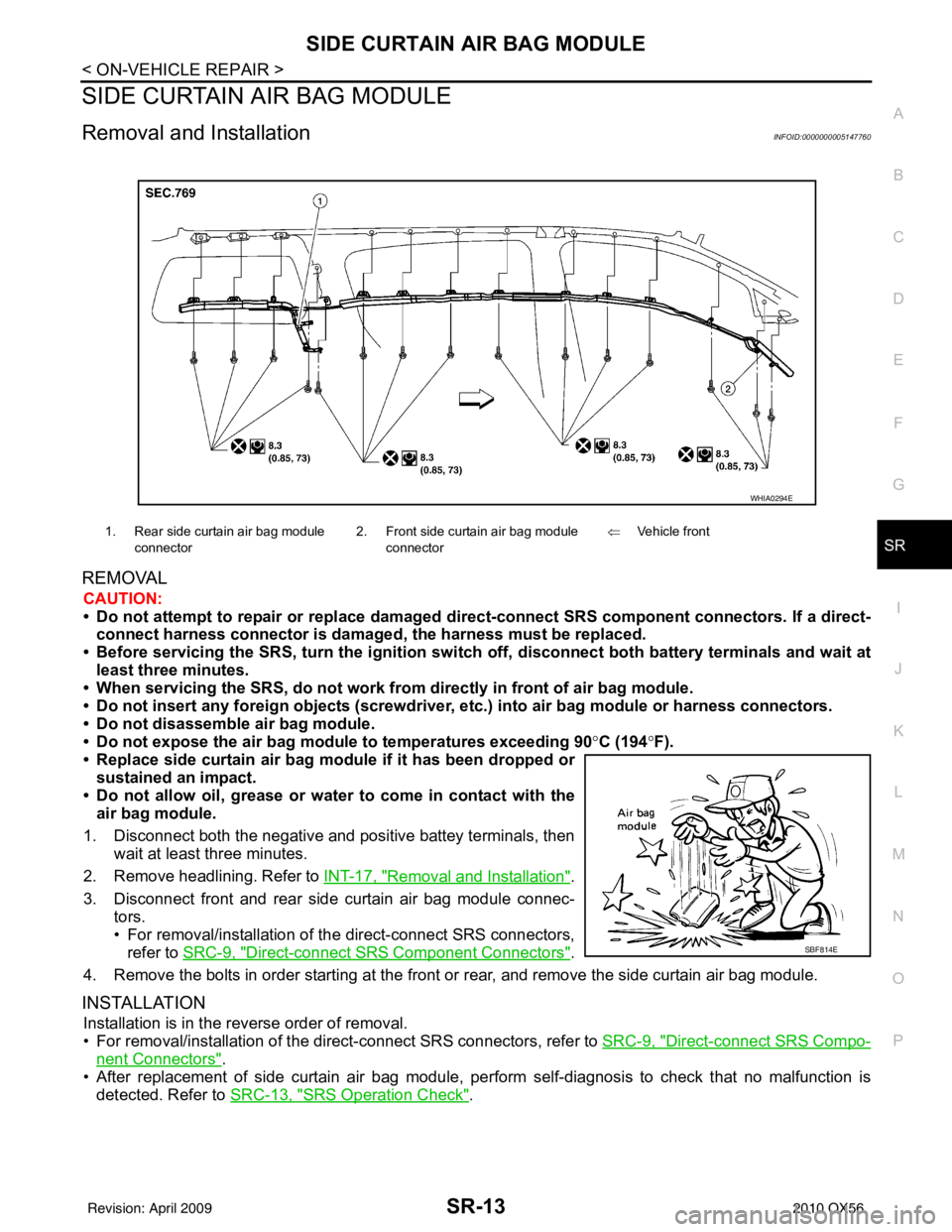
Removal and InstallationINFOID:0000000005147760
REMOVAL
CAUTION:
• Do not attempt to repair or replace damaged direct-connect SRS component connectors. If a direct- connect harness connector is damage d, the harness must be replaced.
• Before servicing the SRS, turn the ignition switch off, disconnect both battery terminals and wait at
least three minutes.
• When servicing the SRS, do not work from directly in front of air bag module.
• Do not insert any foreign objects (screwdriver, etc.) into air bag module or harness connectors.
• Do not disassemble air bag module.
• Do not expose the air bag modu le to temperatures exceeding 90°C (194 °F).
• Replace side curtain air bag modu le if it has been dropped or
sustained an impact.
• Do not allow oil, grease or water to come in contact with the
air bag module.
1. Disconnect both the negative and positive battey terminals, then wait at least three minutes.
2. Remove headlining. Refer to INT-17, "
Removal and Installation".
3. Disconnect front and rear side curtain air bag module connec- tors.
• For removal/installation of the direct-connect SRS connectors,
refer to SRC-9, "
Direct-connect SRS Component Connectors".
4. Remove the bolts in order starting at the front or rear, and remove the side curtain air bag module.
INSTALLATION
Installation is in the reverse order of removal.
• For removal/installation of the direct-connect SRS connectors, refer to SRC-9, "
Direct-connect SRS Compo-
nent Connectors".
• After replacement of side curtain air bag module, per form self-diagnosis to check that no malfunction is
detected. Refer to SRC-13, "
SRS Operation Check".
1. Rear side curtain air bag module
connector 2. Front side curtain air bag module
connector ⇐
Vehicle front
WHIA0294E
SBF814E
Revision: April 20092010 QX56
Page 3540 of 4210
DIAGNOSIS SENSOR UNITSR-17
< ON-VEHICLE REPAIR >
C
DE
F
G
I
J
K L
M A
B
SR
N
O P
DIAGNOSIS SENSOR UNIT
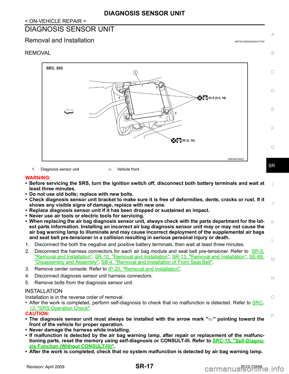
Removal and InstallationINFOID:0000000005147764
REMOVAL
WARNING:
• Before servicing the SRS, turn the ignition switch off, disconnect both battery terminals and wait at
least three minutes.
• Do not use old bolts; replace with new bolts.
• Check diagnosis sensor unit bracket to make sure it is free of deformities, dents, cracks or rust. If it
shows any visible signs of damage, replace with new one.
• Replace diagnosis sensor unit if it has been dropped or sustained an impact.
• Never use air tools or el ectric tools for servicing.
• When replacing the air bag diagnosis sensor unit, always check with the parts department for the lat-
est parts information. Installing an incorrect air bag diagnosis sensor unit may or may not cause the
air bag warning lamp to illuminate and may cause incorrect deployment of the supplemental air bags
and seat belt pre-tensioner in a collision r esulting in serious personal injury or death.
1. Disconnect the both the negative and positive battery terminals, then wait at least three minutes.
2. Disconnect the harness connectors for each air bag module and seat belt pre-tensioner. Refer to SR-5,
"Removal and Installation", SR-10, "Removal and Installation", SR-13, "Removal and Installation", SE-69,
"Disassembly and Assembly", SB-4, "Removal and Installation of Front Seat Belt".
3. Remove center console. Refer to IP-20, "
Removal and Installation".
4. Disconnect diagnosis sensor unit harness connectors.
5. Remove bolts from the diagnosis sensor unit.
INSTALLATION
Installation is in the reverse order of removal.
• After the work is completed, perform self-diagnosis to check that no malfunction is detected. Refer to SRC-
13, "SRS Operation Check".
CAUTION:
• The diagnosis sensor unit must always be installed with the arrow mark " ⇐" pointing toward the
front of the vehicle for proper operation.
• Never damage the harness while installing.
• If malfunction is detected by the air bag warnin g lamp, after repair or replacement of the malfunc-
tioning parts, reset the memory using sel f-diagnosis or CONSULT-III. Refer to SRC-15, "
Self-Diagno-
sis Function (Without CONSULT-III)".
• After the work is completed, check that no system malfunction is detected by air bag warning lamp.
1. Diagnosis sensor unit⇐Vehicle front
AWHIA0159ZZ
Revision: April 20092010 QX56
Page 4074 of 4210
INSPECTION AND ADJUSTMENTWT-5
< BASIC INSPECTION >
C
DF
G H
I
J
K L
M A
B
WT
N
O P
INSPECTION AND ADJUSTMENT
Preliminary CheckINFOID:0000000005148203
1.TIRE PRESSURE
Check all tire pressures. Refer to WT-52, "
Tire".
Do tire pressures match specification?
YES >> GO TO 2.
NO >> Adjust tire pressures to specified value.
2.LOW TIRE PRESSURE WARNING LAMP
Check low tire pressure warning lamp activation.
Does the low tire pressure warning lamp activate for one second when ignition switch is turned ON?
YES >> GO TO 3.
NO >> GO TO WT-37, "
Low Tire Pressure Warning Lamp Does Not Come On When Ignition Switch Is
Turned On".
3.BCM CONNECTOR
1. Disconnect BCM harness connectors.
2. Check terminals for damage or loose connections.
3. Reconnect harness connectors.
Are BCM connectors damaged or loose?
YES >> Repair or replace damaged parts.
NO >> GO TO 4.
4.TRANSMITTER ACTIVATION TOOL
Check battery in transmitter activation tool.
Is transmitter activation tool battery fully charged?
YES >> Perform self-diagnosis. Refer to WT-33, "Self-Diagnosis (With CONSULT-III)".
NO >> Replace battery in transmitter activation tool.
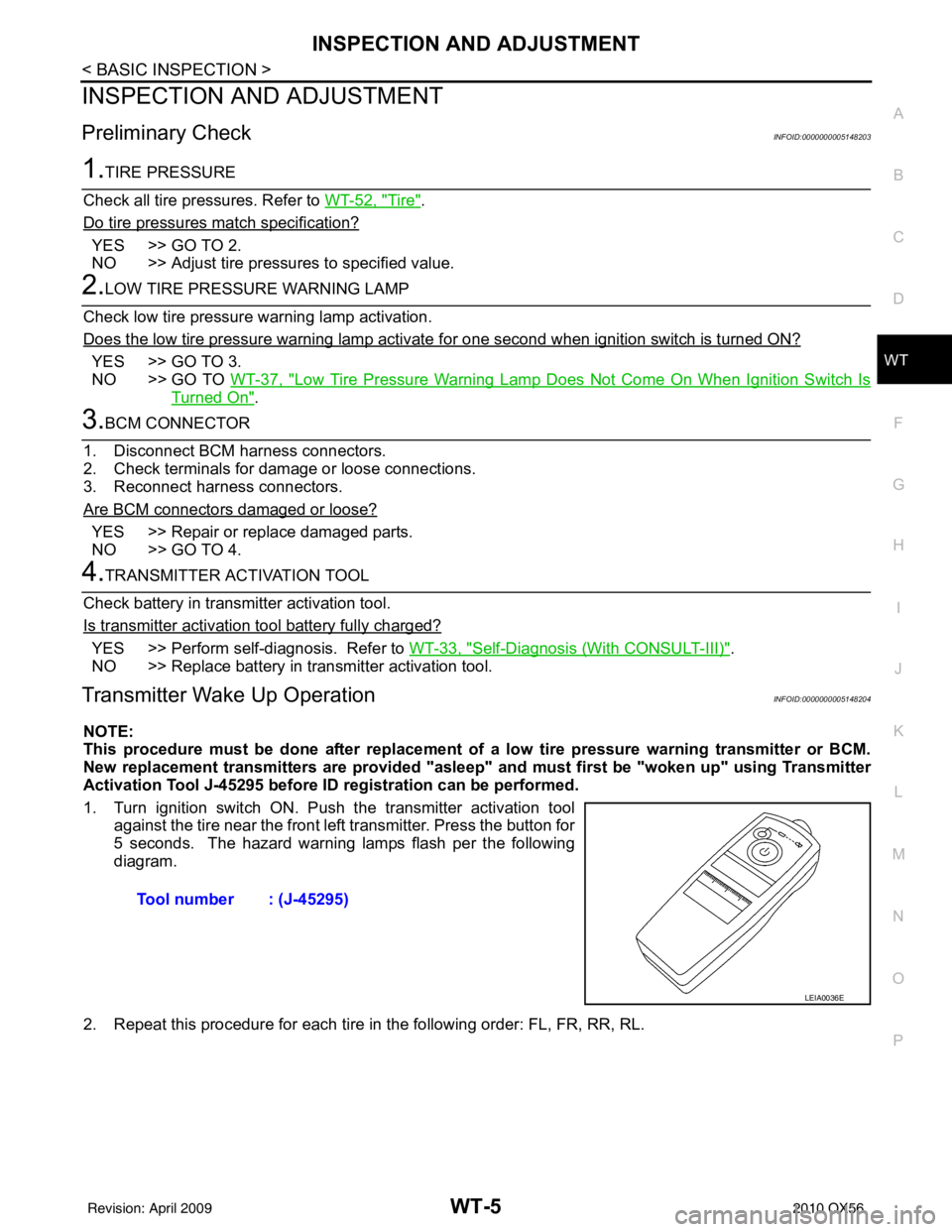
Transmitter Wake Up OperationINFOID:0000000005148204
NOTE:
This procedure must be done after replacement of a low tire pressure warning transmitter or BCM.
New replacement transmitters are provided "asleep" and must first be "woken up" using Transmitter
Activation Tool J-45295 before ID registration can be performed.
1. Turn ignition switch ON. Push the transmitter activation tool against the tire near the front left transmitter. Press the button for
5 seconds. The hazard warning lamps flash per the following
diagram.
2. Repeat this procedure for each tire in the following order: FL, FR, RR, RL. Tool number : (J-45295)
LEIA0036E
Revision: April 20092010 QX56