2010 INFINITI QX56 OBD port
[x] Cancel search: OBD portPage 2241 of 4210

GI-18
< HOW TO USE THIS MANUAL >
TERMINOLOGY
Nonvolatile random access memory NVRAM***
On board diagnostic system OBD system Self-diagnosis
Open loop OL Open loop
Oxidation catalyst OC Catalyst
Oxidation catalytic converter system OC system ***
Oxygen sensor O2S Exhaust gas sensor
Park position switch *** Park switch
Periodic trap oxidizer system PTOX system ***
Positive crankcase ventilation PCV Positive crankcase ventilation
Positive crankcase ventilation valve PCV valve PCV valve
Powertrain cont rol module PCM ***
Programmable read only memory PROM ***
Pulsed secondary air injection control sole-
noid valve PAIRC solenoid valve
AIV control solenoid valve
Pulsed secondary air injection system PAIR system Air induction valve (AIV) control
Pulsed secondary air injection valve PAIR valve Air induction valve
Random access memory RAM ***
Read only memory ROM ***
Scan tool ST ***
Secondary air injection pump AIR pump***
Secondary air injection system AIR system ***
Sequential multiport fuel injection system SFI system Sequential fuel injection
Service reminder indicator SRI***
Simultaneous multiport fuel injection sys-
tem ***
Simultaneous fuel injection
Smoke puff limiter system SPL system ***
Supercharger SC ***
Supercharger bypass SCB ***
System readiness test SRT ***
Thermal vacuum valve TVVThermal vacuum valve
Three way catalyst TWCCatalyst
Three way catalytic converter system TWC system ***
Three way + oxidation catalyst TWC + OCCatalyst
Three way + oxidation catalytic converter
system TWC + OC system
***
Throttle body TB Throttle chamber
SPI body
Throttle body fuel injection system TBI system Fuel injection control
Throttle position TP Throttle position
Throttle position sensor TPS Throttle sensor
Throttle position switch TP switch Throttle switch
Torque converter clutch solenoid valve TCC solenoid valve Lock-up cancel solenoid
Lock-up solenoid
Transmission range switch *** Park/neutral switch
Inhibitor switch
Neutral position switch
NEW TERM
NEW ACRONYM /
ABBREVIATION OLD TERM
Revision: April 20092010 QX56
Page 2609 of 4210
![INFINITI QX56 2010 Factory Service Manual LAN
TROUBLE DIAGNOSISLAN-11
< FUNCTION DIAGNOSIS > [CAN FUNDAMENTAL]
C
D
E
F
G H
I
J
K L
B A
O P
N
Self-DiagnosisINFOID:0000000005152908
CAN Diagnostic Support MonitorINFOID:0000000005146447
CONSULT-I INFINITI QX56 2010 Factory Service Manual LAN
TROUBLE DIAGNOSISLAN-11
< FUNCTION DIAGNOSIS > [CAN FUNDAMENTAL]
C
D
E
F
G H
I
J
K L
B A
O P
N
Self-DiagnosisINFOID:0000000005152908
CAN Diagnostic Support MonitorINFOID:0000000005146447
CONSULT-I](/manual-img/42/57032/w960_57032-2608.png)
LAN
TROUBLE DIAGNOSISLAN-11
< FUNCTION DIAGNOSIS > [CAN FUNDAMENTAL]
C
D
E
F
G H
I
J
K L
B A
O P
N
Self-DiagnosisINFOID:0000000005152908
CAN Diagnostic Support MonitorINFOID:0000000005146447
CONSULT-III and CAN diagnostic support monitor (on-boar
d diagnosis function) are used for detecting root
cause.
MONITOR ITEM (CONSULT-III)
Example: CAN DIAG SUPPORT MNTR indication
Without PAST
DTC Self-diagnosis item
(CONSULT-III indication) DTC detection condition
Inspection/Action
U0101 LOST COMM (TCM) When ECM is not transmitting or receiving CAN commu-
nication signal of OBD (emission-related diagnosis) from
TCM for 2 seconds or more.
Start the inspection. Refer
to the applicable section
of the indicated control
unit.
U0140 LOST COMM (BCM)
When ECM is not transmitting or receiving CAN commu-
nication signal of OBD (emission-related diagnosis) from
BCM for 2 seconds or more.
U0164 LOST COMM (HVAC) When ECM is not transmitting or receiving CAN commu-
nication signal of OBD (emission-related diagnosis) from
A/C auto amp. or unified meter and A/C amp. for 2 sec-
onds or more.
U1000 CAN COMM CIRCUIT ECM
When ECM is not transmitting or receiving
CAN communication signal of OBD (emission-
related diagnosis) for 2 seconds or more.
Except
for ECM When a control unit (except for ECM) is not
transmitting or receiving CAN communication
signal for 2 seconds or more.
U1001 CAN COMM CIRCUIT When ECM is not transmitting or receiving CAN commu-
nication signal other than OBD (emission-related diagno-
sis) for 2 seconds or more.
U1002 SYSTEM COMM When a control unit is not transmitting or receiving CAN
communication signal for 2 seconds or less.
U1010 CONTROL UNIT(CAN) When an error is detected during the initial diagnosis for
CAN controller of each control unit. Replace the control unit
indicating “U1010” or
“P0607”.
P0607
ECM
PKID1075E
Revision: April 20092010 QX56
Page 2649 of 4210
![INFINITI QX56 2010 Factory Service Manual LAN
TROUBLE DIAGNOSISLAN-51
< FUNCTION DIAGNOSIS > [CAN]
C
D
E
F
G H
I
J
K L
B A
O P
N
Never replace the unit even when “NG” is indicated on the “INITIAL DIAG” at this stage. Fo
llow the troub INFINITI QX56 2010 Factory Service Manual LAN
TROUBLE DIAGNOSISLAN-51
< FUNCTION DIAGNOSIS > [CAN]
C
D
E
F
G H
I
J
K L
B A
O P
N
Never replace the unit even when “NG” is indicated on the “INITIAL DIAG” at this stage. Fo
llow the troub](/manual-img/42/57032/w960_57032-2648.png)
LAN
TROUBLE DIAGNOSISLAN-51
< FUNCTION DIAGNOSIS > [CAN]
C
D
E
F
G H
I
J
K L
B A
O P
N
Never replace the unit even when “NG” is indicated on the “INITIAL DIAG” at this stage. Fo
llow the trouble diagnosis proce-
dures.
IPDM E/R
0: Error at present, 1 – 39: Error in the past (Number means the number of times the ignition switch is turned OFF→ ON)
*: 39 or higher number is fixed at 39 until the self-diagnosis result is erased.
DTC IndexINFOID:0000000005152903
ITEMCAN DIAG SUP-
PORT MNTR Description Normal
Error
PRSNT PAST PRSNT PAST
IPDM-E TRANSMIT DIAG Signal transmission status
OKOK
or
1 – 39
*UNKWN 0
ECM Signal receiving status from the ECM
BCM/SEC Signal receiving status from the BCM
DTC Self-diagnosis item
(CONSULT-III indication) DTC detection condition
Inspection/Action
U0101 LOST COMM (TCM) When ECM is not transmitting or receiving CAN commu-
nication signal of OBD (emission-related diagnosis) from
TCM for 2 seconds or more.
Start the inspection. Refer
to the applicable section
of the indicated control
unit.
U0140 LOST COMM (BCM)
When ECM is not transmitting or receiving CAN commu-
nication signal of OBD (emission-related diagnosis) from
BCM for 2 seconds or more.
U0164 LOST COMM (HVAC) When ECM is not transmitting or receiving CAN commu-
nication signal of OBD (emission-related diagnosis) from
A/C auto amp. or unified meter and A/C amp. for 2 sec-
onds or more.
U1000 CAN COMM CIRCUIT ECM
When ECM is not transmitting or receiving
CAN communication signal of OBD (emission-
related diagnosis) for 2 seconds or more.
Except
for ECM When a control unit (except for ECM) is not
transmitting or receiving CAN communication
signal for 2 seconds or more.
U1001 CAN COMM CIRCUIT When ECM is not transmitting or receiving CAN commu-
nication signal other than OBD (emission-related diagno-
sis) for 2 seconds or more.
U1002 SYSTEM COMM When a control unit is not transmitting or receiving CAN
communication signal for 2 seconds or less.
U1010 CONTROL UNIT(CAN) When an error is detected during the initial diagnosis for
CAN controller of each control unit. Replace the control unit
indicating “U1010” or
“P0607”.
P0607
ECM
Revision: April 20092010 QX56
Page 3559 of 4210
ON BOARD DIAGNOSTIC (OBD) SYSTEMSRC-13
< FUNCTION DIAGNOSIS >
C
DE
F
G
I
J
K L
M A
B
SRC
N
O P
ON BOARD DIAGNOSTIC (OBD) SYSTEM
Trouble Diagnosis IntroductionINFOID:0000000005147784
CAUTION:
• Do not use electrical test equipment on any circui t related to the SRS unless instructed to do so in
this Service Manual. SRS wiring harnesses can be id entified by yellow and/or orange harness con-
nectors.
• Do not attempt to repair, splice or modify SRS wiring harnesses. If a harness is damaged, replace it
with a new one.
• Keep ground connections clean.
DIAGNOSIS FUNCTION
The SRS self-diagnosis results can be read by usi ng “AIR BAG” warning lamp and/or CONSULT-III.
The User mode is exclusively prepared for the customer (driver). This mode warns the driver of a system mal-
function through the operation of the “AIR BAG” warning lamp.
The Diagnosis mode allows the technician to locate and inspect the malfunctioning part.
The mode applications for the “AIR BAG” warning lamp and CONSULT-III are as follows:
HOW TO PERFORM TROUBLE DIAGNOSES FOR QUICK AND ACCURATE REPAIR
A good understanding of the malfunction conditions can make troubleshooting faster and more accurate.
In general, each customer feels differently about a malf unction. It is important to fully understand the symp-
toms or conditions for a customer complaint.
Information From Customer
WHAT - Vehicle model
WHEN - Date, Frequencies
WHERE - Road conditions
HOW - Operating conditions, Symptoms
Preliminary Check
Check that the following parts are in good order.
•Battery
•Fuse
• System component-to-harness connections
SRS Operation CheckINFOID:0000000005147785
DIAGNOSTIC PROCEDURE 1
Checking SRS Operation Using “AIR BAG” Warning Lamp—User Mode
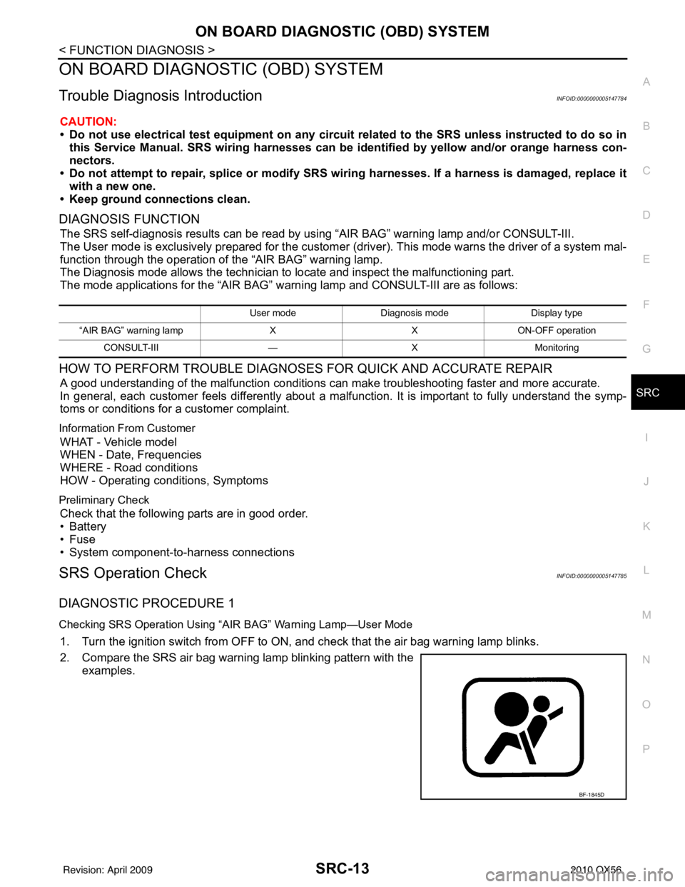
1. Turn the ignition switch from OFF to ON, and check that the air bag warning lamp blinks.
2. Compare the SRS air bag warning lamp blinking pattern with the examples.
User mode Diagnosis mode Display type
“AIR BAG” warning lamp XXON-OFF operation
CONSULT-III —XMonitoring
BF-1845D
Revision: April 20092010 QX56
Page 3727 of 4210
TM-32
< FUNCTION DIAGNOSIS >
DIAGNOSIS SYSTEM (TCM)
DIAGNOSIS SYSTEM (TCM)
CONSULT-III Function (TRANSMISSION)INFOID:0000000005148526
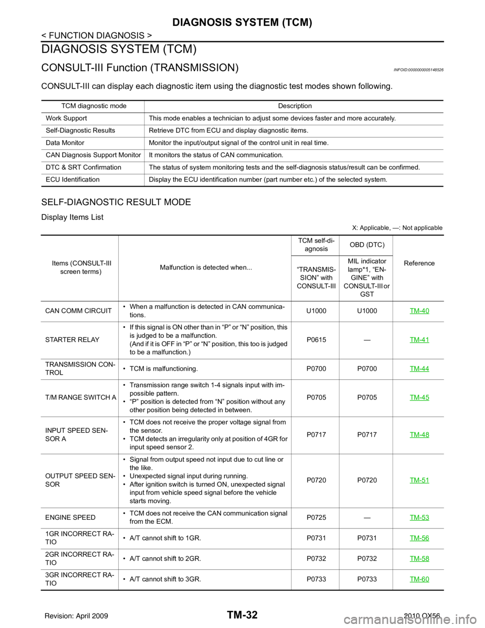
CONSULT-III can display each diagnostic item us ing the diagnostic test modes shown following.
SELF-DIAGNOSTIC RESULT MODE
Display Items List
X: Applicable, —: Not applicable
TCM diagnostic mode Description
Work Support This mode enables a technician to adjust some devices faster and more accurately.
Self-Diagnostic Results Retrieve DTC from ECU and display diagnostic items.
Data Monitor Monitor the input/output signal of the control unit in real time.
CAN Diagnosis Support Monitor It monitors the status of CAN communication.
DTC & SRT Confirmation The status of system monitoring tests and the self-diagnosis status/result can be confirmed.
ECU Identification Display the ECU identification number (part number etc.) of the selected system.
Items (CONSULT-III
screen terms) Malfunction is detected when... TCM self-di-
agnosis OBD (DTC)
Reference
“TRANSMIS-
SION” with
CONSULT-III MIL indicator
lamp*1, “EN-
GINE” with
CONSULT-III or
GST
CAN COMM CIRCUIT • When a malfunction is detected in CAN communica-
tions. U1000 U1000
TM-40
STARTER RELAY• If this signal is ON other than in “P” or “N” position, this
is judged to be a malfunction.
(And if it is OFF in “P” or “N” position, this too is judged
to be a malfunction.) P0615
—TM-41
TRANSMISSION CON-
TROL • TCM is malfunctioning.
P0700 P0700TM-44
T/M RANGE SWITCH A• Transmission range switch 1-4 signals input with im-
possible pattern.
• “P” position is detected from “N” position without any other position being detected in between. P0705 P0705
TM-45
INPUT SPEED SEN-
SOR A• TCM does not receive the proper voltage signal from
the sensor.
• TCM detects an irregularity only at position of 4GR for input speed sensor 2. P0717 P0717
TM-48
OUTPUT SPEED SEN-
SOR• Signal from output speed not input due to cut line or
the like.
• Unexpected signal input during running.
• After ignition switch is turned ON, unexpected signal input from vehicle speed signal before the vehicle
starts moving. P0720 P0720
TM-51
ENGINE SPEED• TCM does not receive the CAN communication signal
from the ECM. P0725
—TM-53
1GR INCORRECT RA-
TIO • A/T cannot shift to 1GR.
P0731 P0731TM-56
2GR INCORRECT RA-
TIO• A/T cannot shift to 2GR.
P0732 P0732TM-58
3GR INCORRECT RA-
TIO• A/T cannot shift to 3GR.
P0733 P0733TM-60
Revision: April 20092010 QX56
Page 3732 of 4210
DIAGNOSIS SYSTEM (TCM)TM-37
< FUNCTION DIAGNOSIS >
CEF
G H
I
J
K L
M A
B
TM
N
O P
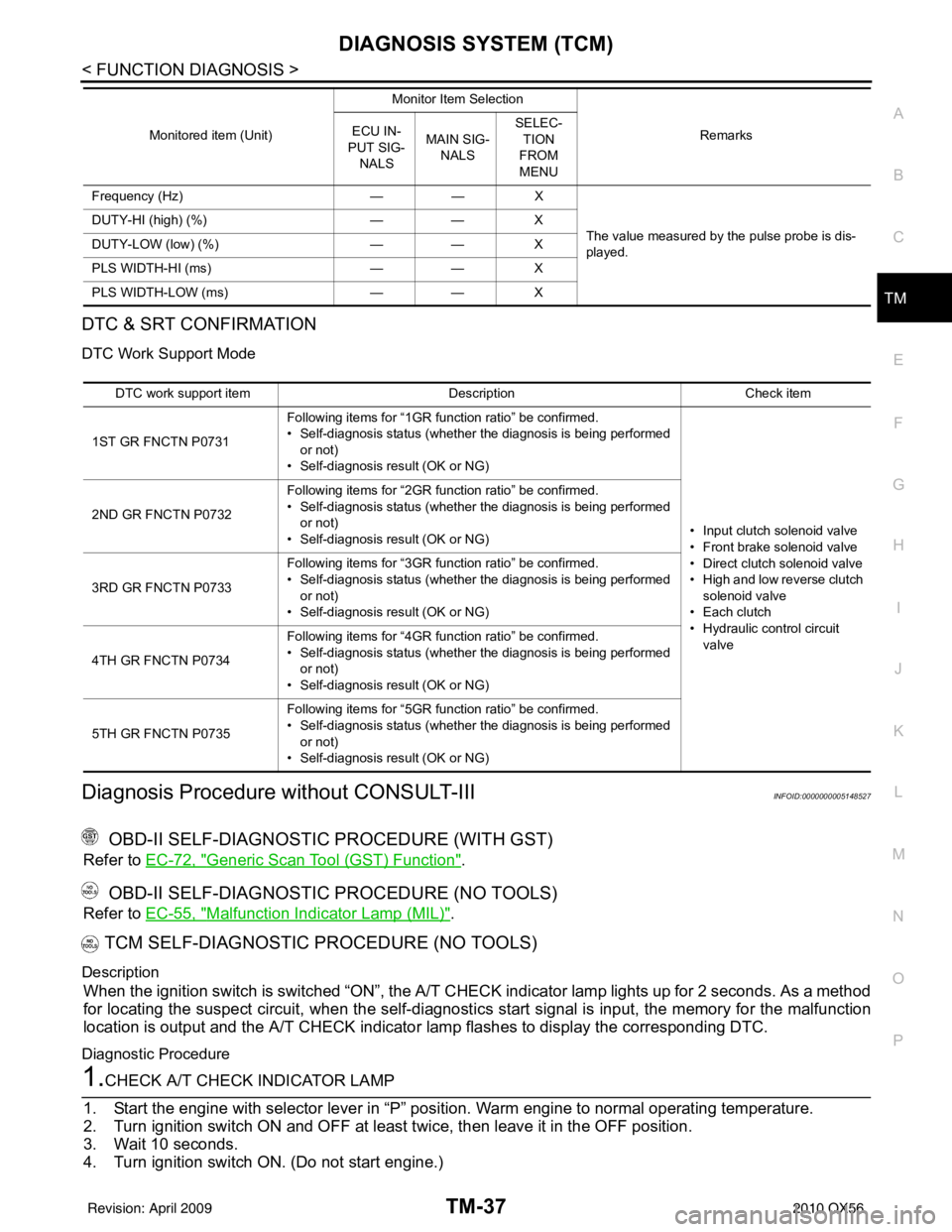
DTC & SRT CONFIRMATION
DTC Work Support Mode
Diagnosis Procedure without CONSULT-IIIINFOID:0000000005148527
OBD-II SELF-DIAGNOSTIC PROCEDURE (WITH GST)
Refer to EC-72, "Generic Scan Tool (GST) Function".
OBD-II SELF-DIAGNOSTIC PROCEDURE (NO TOOLS)
Refer to EC-55, "Malfunction Indicator Lamp (MIL)".
TCM SELF-DIAGNOSTIC PROCEDURE (NO TOOLS)
Description
When the ignition switch is switched “ON”, the A/T CHECK indicator lamp lights up for 2 seconds. As a method
for locating the suspect circuit, when the self-diagnosti cs start signal is input, the memory for the malfunction
location is output and the A/T CHECK indicator lamp flashes to display the corresponding DTC.
Diagnostic Procedure
1.CHECK A/T CHECK INDICATOR LAMP
1. Start the engine with selector lever in “P” pos ition. Warm engine to normal operating temperature.
2. Turn ignition switch ON and OFF at least twice, then leave it in the OFF position.
3. Wait 10 seconds.
4. Turn ignition switch ON. (Do not start engine.)
Frequency (Hz) —— X
The value measured by the pulse probe is dis-
played.
DUTY-HI (high) (%)
—— X
DUTY-LOW (low) (%) —— X
PLS WIDTH-HI (ms) —— X
PLS WIDTH-LOW (ms) —— X
Monitored item (Unit)
Monitor Item Selection
Remarks
ECU IN-
PUT SIG- NALS MAIN SIG-
NALS SELEC-
TION
FROM
MENU
DTC work support item DescriptionCheck item
1ST GR FNCTN P0731 Following items for “1GR function ratio” be confirmed.
• Self-diagnosis status (whether the diagnosis is being performed
or not)
• Self-diagnosis result (OK or NG)
• Input clutch solenoid valve
• Front brake solenoid valve
• Direct clutch solenoid valve
• High and low reverse clutch solenoid valve
• Each clutch
• Hydraulic co ntrol circuit
valve
2ND GR FNCTN P0732
Following items for “2GR function ratio” be confirmed.
• Self-diagnosis status (whether the diagnosis is being performed
or not)
• Self-diagnosis result (OK or NG)
3RD GR FNCTN P0733 Following items for “3GR function ratio” be confirmed.
• Self-diagnosis status (whether the diagnosis is being performed
or not)
• Self-diagnosis result (OK or NG)
4TH GR FNCTN P0734 Following items for “4GR function ratio” be confirmed.
• Self-diagnosis status (whether the diagnosis is being performed
or not)
• Self-diagnosis result (OK or NG)
5TH GR FNCTN P0735 Following items for “5GR function ratio” be confirmed.
• Self-diagnosis status (whether the diagnosis is being performed
or not)
• Self-diagnosis result (OK or NG)
Revision: April 20092010 QX56
Page 3750 of 4210
P0731 1GR INCORRECT RATIOTM-55
< COMPONENT DIAGNOSIS >
CEF
G H
I
J
K L
M A
B
TM
N
O P
P0731 1GR INCORRECT RATIO
DescriptionINFOID:0000000005148568
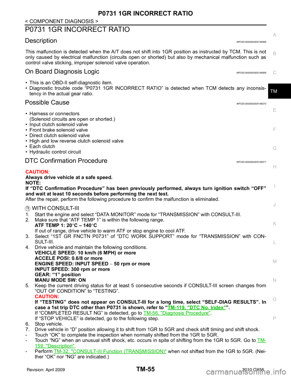
This malfunction is detected when the A/T does not shift into 1GR position as instructed by TCM. This is not
only caused by electrical malfunction (circuits open or shorted) but also by mechanical malfunction such as
control valve sticking, improper solenoid valve operation.
On Board Diagnosis LogicINFOID:0000000005148569
• This is an OBD-II self-diagnostic item.
• Diagnostic trouble code “P0731 1GR INCORRECT RATIO” is detected when TCM detects any inconsis-
tency in the actual gear ratio.
Possible CauseINFOID:0000000005148570
• Harness or connectors (Solenoid circuits are open or shorted.)
• Input clutch solenoid valve
• Front brake solenoid valve
• Direct clutch solenoid valve
• High and low reverse clutch solenoid valve
• Each clutch
• Hydraulic control circuit
DTC Confirmation ProcedureINFOID:0000000005148571
CAUTION:
Always drive vehicle at a safe speed.
NOTE:
If “DTC Confirmation Procedure” has been previously performed, always turn ignition switch “OFF”
and wait at least 10 seconds before performing the next test.
After the repair, perform the following procedure to confirm the malfunction is eliminated.
WITH CONSULT-III
1. Start the engine and select “DATA MONITOR” mode for “TRANSMISSION” with CONSULT-III.
2. Make sure that “ATF TEMP 1” is within the following range. ATF TEMP 1: 20 °C – 140 °C
If out of range, drive vehicle to warm ATF or stop engine to cool ATF.
3. Select “1ST GR FNCTN P0731” of “DTC WO RK SUPPORT” mode for “TRANSMISSION” with CON-
SULT-III.
4. Drive vehicle and maintain the following conditions. VEHICLE SPEED: 10 km/h (6 MPH) or more
ACCELE POSI: 0.6/8 or more
ENGINE SPEED: INPUT SPEED − 50 rpm or more
INPUT SPEED: 300 rpm or more
GEAR: “1” position
MANU MODE SW: ON
5. Keep the current driving status for at least 5 consecutive seconds if CONSULT-III screen changes from “OUT OF CONDITION” to “TESTING”.
CAUTION:
If “TESTING” does not appear on CONSULT-III for a long time, select “SELF-DIAG RESULTS”. In
case a 1st trip DTC other than P0731 is shown, refer to “ TM-119, "
DTC No. Index"”.
If “COMPLETED RESULT NG” is detected, go to TM-56, "
Diagnosis Procedure".
If “STOP VEHICLE” is detec ted, go to the following step.
6. Stop vehicle.
7. Drive vehicle in “D” position allowing it to shift from 1GR to 5GR and check shift timing and shift shock.
- Touch “OK” to complete the inspection when normally shifted from the 1GR to 5GR.
- Touch “NG” when an unusual shift shock, etc. occurs in spite of shifting from the 1GR to 5GR. Go to TM-
159, "Description".
-Perform TM-32, "
CONSULT-III Functi on (TRANSMISSION)" when not shifted from the 1GR to 5GR. (Nei-
ther “OK” nor “NG” are indicated.)
Revision: April 20092010 QX56
Page 3752 of 4210
P0732 2GR INCORRECT RATIOTM-57
< COMPONENT DIAGNOSIS >
CEF
G H
I
J
K L
M A
B
TM
N
O P
P0732 2GR INCORRECT RATIO
DescriptionINFOID:0000000005148573
This malfunction is detected when the A/T does not shift into 2GR position as instructed by TCM. This is not
only caused by electrical malfunction (circuits open or shorted) but also by mechanical malfunction such as
control valve sticking, improper solenoid valve operation.
On Board Diagnosis LogicINFOID:0000000005148574
• This is an OBD-II self-diagnostic item.
• Diagnostic trouble code “P0732 2GR INCORRECT RATIO” detected when TCM detects any inconsistency
in the actual gear ratio.
Possible CauseINFOID:0000000005148575
• Harness or connectors (Solenoid circuits are open or shorted.)
• Input clutch solenoid valve
• Front brake solenoid valve
• Direct clutch solenoid valve
• High and low reverse clutch solenoid valve
• Each clutch
• Hydraulic control circuit
DTC Confirmation ProcedureINFOID:0000000005148576
CAUTION:
Always drive vehicle at a safe speed.
NOTE:
If “DTC Confirmation Procedure” has been previously performed, always turn ignition switch “OFF”
and wait at least 10 seconds before performing the next test.
After the repair, perform the following procedure to confirm the malfunction is eliminated.
WITH CONSULT-III
1. Start the engine and select “DATA MONITOR” mode for “TRANSMISSION” with CONSULT-III.
2. Make sure that “ATF TEMP 1” is within the following range. ATF TEMP 1: 20 °C – 140 °C
If out of range, drive vehicle to warm ATF or stop engine to cool ATF.
3. Select “2ND GR FNCTN P0732” of “DTC WORK SUPPORT” mode for “TRANSMISSION” with CON-
SULT-III.
4. Drive vehicle and maintain the following conditions. VEHICLE SPEED: 10 km/h (6 MPH) or more
ACCELE POSI: 0.6/8 or more
ENGINE SPEED: INPUT SPEED − 50 rpm or more
INPUT SPEED: 300 rpm or more
GEAR: “2” position
MANU MODE SW: ON
5. Keep the current driving status for at least 5 consecutive seconds if CONSULT-III screen changes from “OUT OF CONDITION” to “TESTING”.
CAUTION:
If “TESTING” does not appear on CONSULT-III for a long time, select “SELF-DIAG RESULTS”. In
case a 1st trip DTC other than P0732 is shown, refer to “ TM-119, "
DTC No. Index"”.
If “COMPLETED RESULT NG” is detected, go to TM-58, "
Diagnosis Procedure".
If “STOP VEHICLE” is detec ted, go to the following step.
6. Stop vehicle.
7. Drive vehicle in “D” position allowing it to shift from 1GR to 5GR and check shift timing and shift shock.
- Touch “OK” to complete the inspection when normally shifted from the 1GR to 5GR.
- Touch “NG” when an unusual shift shock, etc. occurs in spite of shifting from the 1GR to 5GR. Go to TM-
159, "Description".
-Perform TM-32, "
CONSULT-III Functi on (TRANSMISSION)" when not shifted from the 1GR to 5GR. (Nei-
ther “OK” nor “NG” are indicated.)
Revision: April 20092010 QX56