Page 3216 of 4210
SERVICE DATA AND SPECIFICATIONS (SDS)RSU-29
< SERVICE DATA AND SPECIFICATIONS (SDS)
C
DF
G H
I
J
K L
M A
B
RSU
N
O P
SERVICE DATA AND SPECIFICATIONS (SDS)
SERVICE DATA AND SPECIFICATIONS (SDS)
Wheel AlignmentINFOID:0000000005148142
Ball JointINFOID:0000000005148143
Camber
Degree minute (decimal degree) Minimum
0° 0 ′ (0 °)
Nominal - 0° 30 ′ (-0.5 °)
Maximum - 1° 0 ′ (-1.0 °)
Cross camber 0° 45 ′ (0.75 °)
To e - i n Distance (A - B)
Minimum
0 mm (0 in)
Nominal 3.3 mm (0.130 in)
Maximum 6.6 mm (0.260 in)
Cross toe 2 mm (0.079 in)
Angle (left, right)
Degree minute (decimal degree) Minimum
0° 0 ′ (0 °)
Nominal 0° 7 ′ (0.11 °)
Maximum 0° 14 ′ (0.22 °)
Cross toe 0° 8 ′ (0.14 °)
SFA234AC
Swinging force (A)
(measurement point: cotter pin hole of ball stud) 11.4 - 145.5 N (1.16 - 14.8 kg, 2.56 - 32.7 lb)
Turning torque (B) 0.5 - 6.4 N·m (0.06 - 0.65 kg-m, 5 - 56 in-lb)
Vertical end play (C) 0 mm (0 in)
SFA858A
Revision: April 20092010 QX56
Page 3318 of 4210

SE-46
< PRECAUTION >
PRECAUTIONS
5. When the repair work is completed, return the ignition switch to the ″LOCK ″ position before connecting
the battery cables. (At this time, the steering lock mechanism will engage.)
6. Perform a self-diagnosis check of a ll control units using CONSULT-III.
Precaution for WorkINFOID:0000000005147404
• When removing or disassembling each component, be careful not to damage or deform it. If a component
may be subject to interference, be sure to protect it with a shop cloth.
• When removing (disengaging) components with a screwdriver or similar tool, be sure to wrap the component
with a shop cloth or vinyl tape to protect it.
• Protect the removed parts with a shop cloth and keep them.
• Replace a deformed or damaged clip.
• If a part is specified as a non-reusable part, always replace it with new one.
• Be sure to tighten bolts and nuts securely to the specified torque.
• After re-installation is completed, be sure to check that each part works normally.
• Follow the steps below to clean components.
- Water soluble foul: Dip a soft cloth into lukewarm water, and wring the water out of the cloth to wipe the fouled area.
Then rub with a soft and dry cloth.
- Oily foul: Dip a soft cloth into lukewarm water wit h mild detergent (concentration: within 2 to 3%), and wipe
the fouled area.
Then dip a cloth into fresh water, and wring the water out of the cloth to wipe the detergent off. Then rub with
a soft and dry cloth.
• Do not use organic solvent such as thinner, benzene, alcohol, or gasoline.
• For genuine leather seats, use a genuine leather seat cleaner.
Revision: April 20092010 QX56
Page 3644 of 4210
ST-6
< PREPARATION >
PREPARATION
Commercial Service Tool
INFOID:0000000005147858
ST3127S000
(J-25765-A)
Preload gauge
1. GG9103000
(J-25765-A)
Torque wrench
2. HT62940000
(—)
Socket adapter
3. HT62900000
(—)
Socket adapter Inspecting sliding torque, steering torque and
rotating torque for ball joint
(—)
J-44372
Spring gauge Measure steering wheel turning force or rack
sliding force
Tool number
(Kent-Moore No.)
Tool name
Description
S-NT541
LST024
Tool name
Description
Power tool Removing nuts and bolts
PBIC0190E
Revision: April 20092010 QX56
Page 3650 of 4210

ST-12
< SYMPTOM DIAGNOSIS >
NOISE, VIBRATION AND HARSHNESS (NVH) TROUBLESHOOTING
SYMPTOM DIAGNOSIS
NOISE, VIBRATION AND HARSHNESS (NVH) TROUBLESHOOTING
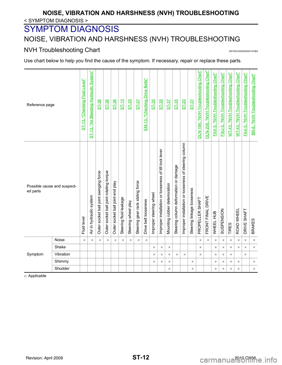
NVH Troubleshooting ChartINFOID:0000000005147864
Use chart below to help you find the cause of the symp tom. If necessary, repair or replace these parts.
×: ApplicableReference page
ST-13, "
Checking Fluid Level
"
ST-13, "
Air Bleeding Hydraulic System
"
ST-36ST-36ST-36ST-13ST-35ST-37
EM-13, "
Checking Drive Belts
"
ST-35ST-35ST-37ST-35ST-20ST-37
DLN-184, "
NVH Troubleshooting Chart
"
DLN-208, "
NVH Troubleshooting Chart
"
FAX-5, "
NVH Troubleshooting Chart
"
FSU-5, "
NVH Troubleshooting Chart
"
WT-43, "
NVH Troubleshooting Chart
"
WT-43, "
NVH Troubleshooting Chart
"
FAX-5, "
NVH Troubleshooting Chart
"
BR-6, "
NVH Troubleshooting Chart
"
Possible cause and suspect-
ed parts
Fluid level
Air in hydraulic system
Outer socket ball joint swinging force
Outer socket ball joint rotating torque
Outer socket ball joint end play
Steering fluid leakage
Steering wheel play
Steering gear rack sliding force
Drive belt looseness
Improper steering wheel
Improper installation or looseness of tilt lock lever
Mounting rubber deterioration
Steering column deformation or damage
Improper installation or looseness of steering column
Steering linkage looseness
PROPELLER SHAFT
FRONT FINAL DRIVE
WHEEL HUB
SUSPENSION
TIRES
ROAD WHEEL
DRIVE SHAFT
BRAKES
Symptom
Noise
× × ××××× × × ××××××× ×
Shake ×××× ××××× ×
Vibration ××××× × ××× ×
Shimmy ××× × ×××× ×
Shudder × × ×××× ×
Revision: April 20092010 QX56
Page 3664 of 4210
ST-26
< REMOVAL AND INSTALLATION >
POWER STEERING OIL PUMP
POWER STEERING OIL PUMP
Removal and InstallationINFOID:0000000005147874
REMOVAL
1. Drain power steering fluid from reservoir tank.
2. Remove engine room cover. Refer to EM-24, "
Removal and Installation".
3. Remove air duct assembly. Refer to EM-25, "
Removal and Installation".
4. Remove power steering reservoir tank.
5. Remove serpentine drive belt belt from auto tensioner and power steering pump. Refer to EM-13,
"Removal and Installation".
6. Disconnect pressure sensor electrical connector.
7. Remove high pressure and low pressure piping from power steering oil pump. Refer to ST-27
.
8. Remove bolts, then remove power steering pump.
INSTALLATION
Installation is in the reverse order of removal. Refer to ST-27 for tightening torque.
• After installation, bleed air. Refer to ST-13, "
Air Bleeding Hydraulic System".
NOTE:
Belt tension is automatic and requires no adjustment.
Revision: April 20092010 QX56
Page 3666 of 4210
ST-28
< REMOVAL AND INSTALLATION >
HYDRAULIC LINE
• Confirm mating marks are aligned with hose and clamp, then cor-rect if needed.
• To install eye joint, align projection of eye joint with notch of power steering pump, and attach eye joint to power steering pump prop-
erly. Tighten eye bolt by hand fully, then torque to specification.
SGIA0563E
WGIA0089E
Revision: April 20092010 QX56
Page 3670 of 4210

ST-32
< DISASSEMBLY AND ASSEMBLY >
POWER STEERING GEAR AND LINKAGE
Gear Housing Assembly
Check gear housing assembly for dents, cracks or damage. Replace as an assembly if necessary.
Outer Socket and Inner Socket
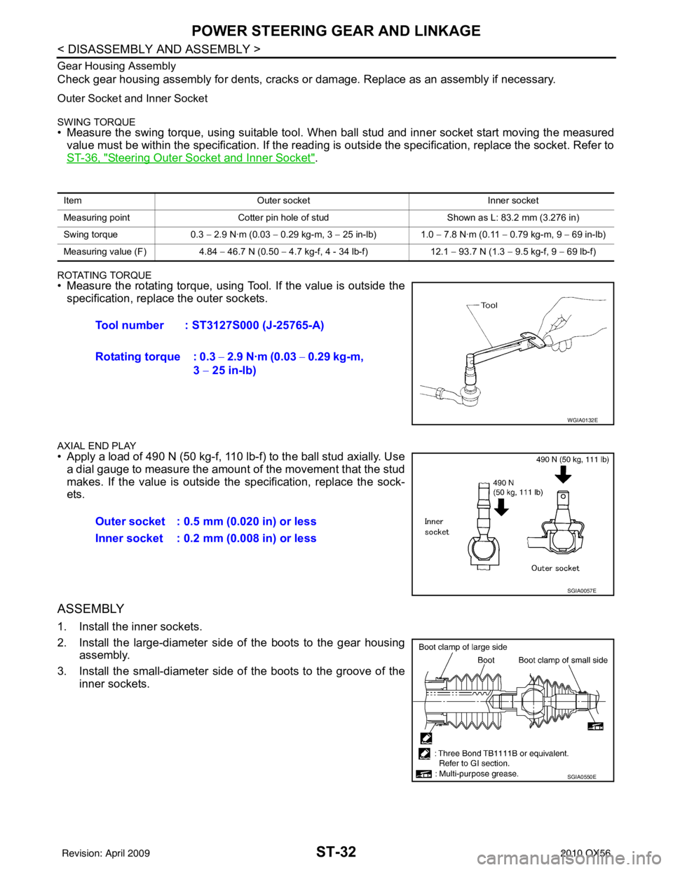
SWING TORQUE• Measure the swing torque, using suitable tool. When ball stud and inner socket start moving the measured
value must be within the specification. If the reading is outside the specification, replace the socket. Refer to
ST-36, "
Steering Outer Socket and Inner Socket".
ROTATING TORQUE• Measure the rotating torque, using Tool. If the value is outside the specification, replace the outer sockets.
AXIAL END PLAY• Apply a load of 490 N (50 kg-f, 110 lb-f) to the ball stud axially. Usea dial gauge to measure the amount of the movement that the stud
makes. If the value is outside the specification, replace the sock-
ets.
ASSEMBLY
1. Install the inner sockets.
2. Install the large-diameter side of the boots to the gear housing assembly.
3. Install the small-diameter side of the boots to the groove of the inner sockets.
Item Outer socket Inner socket
Measuring point Cotter pin hole of stud Shown as L: 83.2 mm (3.276 in)
Swing torque 0.3 − 2.9 N·m (0.03 − 0.29 kg-m, 3 − 25 in-lb) 1.0 − 7.8 N·m (0.11 − 0.79 kg-m, 9 − 69 in-lb)
Measuring value (F) 4.84 − 46.7 N (0.50 − 4.7 kg-f, 4 - 34 lb-f) 12.1 − 93.7 N (1.3 − 9.5 kg-f, 9 − 69 lb-f)
Tool number : ST3127S000 (J-25765-A)
Rotating torque : 0.3 − 2.9 N·m (0.03 − 0.29 kg-m,
3 − 25 in-lb)
WGIA0132E
Outer socket : 0.5 mm (0.020 in) or less
Inner socket : 0.2 mm (0.008 in) or less
SGIA0057E
SGIA0550E
Revision: April 20092010 QX56
Page 3674 of 4210
ST-36
< SERVICE DATA AND SPECIFICATIONS (SDS)
SERVICE DATA AND SPECIFICATIONS (SDS)
Inspection After Installation
Steering Outer Socket and Inner SocketINFOID:0000000005147881
Unit: mm (in)
Range “A”18°
Tilt mechanism range (Manual tilt) 3° per notch at 5 steps
WGIA0083E
Tie-rod ball joint outer socket Swinging torque (F)
0.3 − 2.9 N·m (0.03 − 0.29 kg-m, 3 − 25 in-lb)
Measurement on spring balance
• Measuring point: cotter pin hole of stud 4.84
− 46.7 N (0.50 − 4.7 kg-f, 4 − 34 lb-f)
Rotating torque 0.3 − 2.9 N·m (0.03 − 0.29 kg-m, 3 − 25 in-lb)
Axial end play 0.5 mm (0.020 in) or less
Tie-rod ball joint inner socket Swinging torque
1.0 − 7.8 N·m (0.11 − 0.79 kg-m, 9 − 69 in-lb)
Measurement on spring balance
• Measuring point: L mark see above, L=83.2 mm (3.276 in). 12.1
− 93.7 N (1.3 − 9.5 kg-f, 9 − 69 lb-f)
Axial end play 0.2 mm (0.08 in) or less
SGIA0358E
Inner socket length “L” 102.2 (4.02)
SGIA0167E
Revision: April 20092010 QX56